1
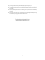
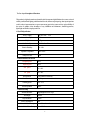
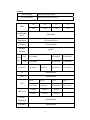
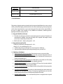
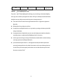
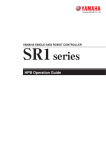
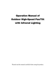
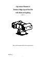
Operation Manual of Outdoor High-Speed Pan/Tilt with Infrared Lighting VER: 2.0 Please read the manual carefully before using the product. Safe Note: 1 Note: To avoid electric shock danger, please don’t open. Note: To avoid electric shock, please don’t dismantle by yourself. There is not parts can be dismantled by user himself, should be maintained by qualified. The arrowhead sigh shined in triangle to remind user the non-insulated dangerous voltage appearing near the product is dangerous to human beings. ! The note sign in triangle is to remind user refer to the spec on important operation and maintenance. The serial NO. is signed at the bottom or side. Please fill the serial NO. in the blank below, and keep the spec well to check when needed. Content 2 Note………………………………………………………………………………5 The first chapter Function………………………………………7 1.1 P/T/Z spec……………………………………………………………………7 1.2 P/T/Z basic parameter………………………………………………………7 1.3 Infrared parameter……………………………………………………………7 1.4 P/T/Z alarm……………………………………………………………………7 1.5 Camera parameter………………………………………………………………8 1.6 P/T/Z function………………………………………………………………9 The second chapter menu setup……………………………………………………12 System connect pic………………………………………………………………12 2.1 Menu basic operation………………………………………………………13 2.2 Menu setup………………………………………………………………………13 2.2.1 MAIN MENU ……………………………………………………… 13 2.2.2 DISPLAY SETUP ………………………………………………13 2.2.3 CAMERA SETUP………………………………………………14 2.2.4 CONTROL SETUP……………………………………………14 2.2.5 HOME OPTION………………………………………………15 2.2.6 CAMERA MASK SET…………………………………15 2.2.7 PROGRAM ………………………………………………………15 2.3 Menu appendix………………………………………………………16 2.3.1 Patrol program operation………………………………………16 2.3.2 Preset title program operation………………………………………17 The third chapter P/T/Z parameter setup…………………………………18 3.1 End-meet resistance setup……………………………………………18 3.2 Address dial setup……………………………………………………18 3.3 Protocol and acquiescent baud rate setup………………………………20 3.4 P/T/Z communicate baud rate setup(two bits after SW2)…………20 The fourth chapter P/T/Z installation spec…………………………………22 4.1 Safe measure……………………………………………………………22 3 4.2 Notice……………………………………………………………………22 4.3 Environment request…………………………………………………………22 4.4 Route safe………………………………………………………………22 4.5 Installation prepare……………………………………………………23 4.6 Installation way introduction………………………………………… 24 4.7 Installation spec……………………………………………………………25 4.7.1 Sun Shield installation………………………………………25 4.7.2 On Vehicle installation…………………………………………………25 4.7.3 Wall installation……………………………………………………26 4.8 P/T/Z line out way ……………………………………………………………… 27 Appendix:Usual trouble analysis…………………………………………29 Appendix:24VAC distance relation between route and transmission distance…30 Appendix:lightning strike proof, surge……………………………………31 Appendix:Maintenance service terms………………………………32 4 Notes for Attention: 1. Read the manual carefully before installing the product. ¾ Electric safe Observe all national and area electric safety standards in application. Adopt special power supply attached the product. There are two input ways of power supply: DC12V (vehicle) and AC24V (normal pan/tilt). Observe all electric safety standards in application and adopt special power supply attached the product. RS-485 control signal and video signal should be kept enough distance with the high voltage devices and cables during the course of transmission, and take protection measures such as anti-lightning and surging etc. if necessary. ¾ Transport carefully Avoid incorrect operation methods such as heavy pressing, strong vibration, dip in, etc. during the course of transportation, store and installation otherwise the product could be damaged. There are sophisticated optical and electronic components inside the product. Please do not dismount components inside the product to avoid occurrence of trouble. Whether delivery or return for repair, if there is no part inside the product, then needs repair by customer himself. ¾ Install carefully Read the manual carefully before installing the product. Take the module gently, do not press structure parts, otherwise the machinery trouble will be caused; Transparent cover is advanced optic products, avoid directly touch result in scratches on the cover, effect image quality. ¾ The competency requirement on maintenance person The installation, maintenance about the device should be installed by the qualified maintenance technologic person. When the device has problem, find the problem according to spec first instead of maintaining it in a hurry, find the professional maintenance person if can’t find the reason. About the maintenance, should be carry out by the authorized maintenance person. ¾ Don’t dismantle camera arbitrarily Don’t dismantle the screws or protective cover, there is no parts can be dismantled by user himself, should be maintained by the qualified. ¾ Environment request Temperature: -35°~+55° Humidity:90% Air pressure:86-106kpa Power supply:DC12V(Vehicle)/AC24V(normal pan/tilt) ¾ Installation request z When installing, please install in the place which have enough bearing capacity. 5 z Don’t storage, install and use the product in inflammable, explosive dangerous eare. z Do not apply the product under the state exceeding limited temperature, humidity or specifications of power supply. z Please don’t dismantle parts inside device to effect using, there is no parts inside can be maintained by user himself. z Do not aim the camera at the sun or very bright object, aim or monitor bright and still object for a long time whether the power supply of the camera is switched on or off. The whole machine can be kept repair for 3 years (Remark: the camera is kept repair for 1 year). 6 The first chapter Description of Functions This product is a high-tech monitor and controller which incorporates high definition color camera, universal variable pan/tilt, infrared lighting, multi-functional decoder, character superimposing, alarm input/output into a whole, reduces interconnections to a great extent among parts in the system and rises up the reliability of the system. In addition it has advantages of easy installation and maintenance, beautiful appearance, lightweight and flexible, simple operation etc. 1.1 Pan/Tilt Specification Power Supply AC24V±10% 2.5A Power Consumption 50VA Weight 7.5Kg Installation Style Relative Humidity Operation Temperature Waterproof Class Plain Base Installation 10~90% -35°~55Ԩ IP66 1.2 Basic Functions of Pam/Tilt Pan preset speed 80°/s Tilt preset speed 60°/s Pan speed 0º~60°/s Tilt speed 0º~40°/s Preset Position 128 positions in maximum Patrol Function 6 patrol patterns are stored in maximum Scanning Speed 0.5~30°/s Self-Study Pattern 40sec 1.3 Infrared Lamp Infrared Illuminator High Brightness LED×36pcs Wavelength 850nm Project Distance 120m Power Consumption Control of Infrared Lamp Service Life of Infrared Lamp 4W Auto/Manual control on menu Over 20000 hours 7 1.4 Alarm Four Channel Inputs Normal Open, closing for alarm One Channel Output Normal Open, Normal Close Output 1.5 Camera Functions 18× 22× 23× 27× D/N Color D/N D/N Model Synchronization Inside/Outside System Image Sensor 1/4″Exview HAD CCD Scan System 2:1 scan separate line Horizontal ≥480TVL Resolution PAL 752×582(440K) 758×592(450K) 795×596(470K) NTSC 768×494(380K) 758×504(380K) 811×508(410K) 1Lux / 0.01Lux 1Lux / 0.01Lux Effective Pixels Lowest LUX 1Lux /0.01Lux 0.2Lux F1.6 Iris Automatic/Manual Focus Automatic/Manual Optic 18× Optic 22× Optic 23× Optic 27× f=4.1 to 73.8 mm f=4 to 88 mm f=3.6 to 82.8 mm f=3.6 to 98 mm Zoom Wide:48° Wide:47° Wide:54° TELE:2.7° TELE:2.2° TELE:2.5° Angle of view Backlight Automatic/Manual Compensation White balance Automatic/Manual 8 Magnification Automatic/Manual Signal/Noise Ratio ≥50dB Signal/Noise Ratio Compound Signal 1.0Vp-p/75Ω 1.6 Pan/Tilt Functions This product is a high-tech monitor and controller which incorporates high definition color camera, universal variable pan/tilt, infrared lighting, multi-functional decoder, character superimposing, alarm input/output into a whole, reduces interconnections to a great extent among parts in the system and rises up the reliability of the system. In addition it has advantages of easy installation and maintenance, beautiful appearance, lightweight and flexible, simple operation etc. 1.6.1 Integrated Multi-Protocol Decoder ¾ The built-in decoder integrates 16 kinds of communication protocols in maximum. The baud rate of communication is adjustable. It has strong universality and is compatible with multiple common systems only by simple setting on the dip-switch. ¾ RS485 serial control: addresses of the pan/tilt 1 – 1023. 1.6.2 Integrated Panoramic Pan/Tilt Panning 360º continuously, manual pan speed 0º~60°/s; tilt range: -85º~90º, manual tilt speed 0º~40°/s. ¾ Smooth running at low speed with super lower noise. Images have no fluttering. ¾ Panoramic monitor without black spot and the positioning accuracy can reach ±0.1°. 1.6.3 High Degree of Intelligence ¾ Preset memory has as much as 128 positions. Data are kept in memory even power is failure. ¾ Horizontal scan between two positions are supported. Scan speed can be altered and direction of pan can be selected freely. The pan/tilt can make scan larger or smaller than 180° between any two positions with adjustable speed. ¾ Six groups of programmable patrol pattern are available with 16 preset positions each. The running speed and retained time for each preset position are adjustable respectively. ¾ Self-study function of pattern. The system can simulate the PTZ route of user’s operation within 40 seconds and data are kept in memory even power is failure. ¾ Character superimposing function. It can display the address of the pan/tilt, title of the preset position etc. ¾ Long focus speed-limited function. The pan/tilt can adjust automatically the manual control speed depending on the focal length of the camera. The larger the magnification times, the slower the manual control speed thus to ensure searching the target rapidly and accurately. ¾ Integrated multiple protocols. A lot of communication protocols are integrated inside the pan/tilt 9 with selectable baud rates from 2400 bps to 19200 bps. 1.6.4 Camera Function: Refer to Camera ¾ Control Mode of Focal Length: the user can manually adjust the focal length of the camera. ¾ Control of Magnification:the user can “pull up” or “push away” the lens ¾ Backlight Compensation: in case the lit object has dark background and couldn’t be displayed clearly, the user can switch on the backlight compensation . ¾ White Balance: in case images have distorted color on the screen, the user can set various kinds of modes by orders. There are six modes available for selection: trigger mode indoor mode auto tracking white balance manual white balance outdoor mode automatic mode. ¾ AE Mode:manual/automatic setup. ¾ Setup of Low Illumination: normally the camera operates under normal condition. In case when ambient illumination is lower than 1 LUX, the camera can automatically switch into zero illumination state . You can also make the camera under the zero illumination state manually. ¾ Other function: refer to different camera by using system menu to control. 1.6.5 Infrared System ¾ The infrared system is normally under automatic control state. The infrared lamp shall act followed by open/close of the low illumination of the camera; ¾ The open/close state of the infrared lamp can be changed by the menu manually; The default option on the menu of the infrared lamp is OFF. Normally the system detects external illumination and opens/closes the infrared lamp automatically. If the user changes the option of the infrared lamp into ON, the infrared system is changed into the manual control; if changing back into the automatic control, the user should set the option on the menu of the infrared at OFF. 1.6.6 Alarm Input/Output ¾ Four normal-open alarm inputs and close alarm. ¾ One group of the alarm output: normal-open and normal-close style. When the system identifies the alarm signal, it can start the pan/tilt and the camera immediately as per the setup of the program, and switch the image in the alarm zone into the main monitor, adjust the position of the alarm position, monitor the preset position and reflect conditions of the alarm zone as fast as it can. ¾ See picture one 10 Picture one The alarm input should be the input signal with the switch type. Any other types of the input signal (such as voltage signal) could damage the dome camera. In case multiple channels have alarm signals, the pan/tilt shall response upon them on by one with the interval of 2 seconds. The pan/tilt shall do not response upon functions such as “pan”, “patrol” and “self-study” when the alarm signal in inputted. 11 The second chapter Setup of the Menu of the Pan/Tilt Schematic Drawing of Pan/tilt: 1)Schematic Drawing of the Vehicle-Carried Pan/Tilt (the shock absorber is added), see picture 2: Monitor Video input A B C D E F G H SELECTED ON-LINE DVR Keyboard RS485 BUS Al ar m Alarm Box Picture 2 2)Schematic Drawing of Common Pan/tilt, see picture 3: Vi deo Modem Bank Tel ecommuni cat i on DC/ AC I nver t er AC220V Moni t or RS485 DC12V DC12V St or age bat t er y PTZ Cont r ol l er Picture 3 12 1. 2.1 Basic Operation of the Menu Open the main menu by the control keyboard or the matrix through the order “calling the 64th preset position” or the order in 4 seconds “calling the 1st preset position” in two fast and consecutive times. (There is no other control orders during the two calling times) When the menu is displayed on the screen, operate “TILT UP”, “TILT DOWN” to move the cursor to the option to be set; and operate “PAN LEFT”, “PAN RIGHT” to modify contents or order to enter into the said option. To speed up operation by making the joystick towards one direction for more than one second. All setup on the menu could not be lost even the power is failed. Special uses can be seen from the description of the menu. ¾ 2.2 Setup of the Menu 2.2.1 MAIN MENU ¾ DISPLAY SETUP:To enter into the sub-menu of the display setup which can set the ID display, title isplay of the presser position and the display of the camera itself. ¾ CAMERA SETUP:To enter into the sub-menu of the common data of the camera. ¾ CONTROL SETUP:To enter into the sub-menu of the control data of the pan/tilt. ¾ CAMERA MASK SET:To enter into the sub-menu of the control data MAIN MENU 1. DI SPLAY SETUP 2. CAMERA SETUP 3. CONTROL SETUP 4. CAMERA MASK SET 5. PROGRAM 6. PAL CAMERA 7. CAM DEFAULT SET 8. RESET PT 9. EXI T of the camera mask. ¾ PROGRAM: To enter into the sub-menu of the enhance function of the menu. ¾ PAL CAMERA:PAL/NTSC To switch modes of PAL/NTSC, being identical with that of the camera. ¾ CAM DEFAULT SET:To recover to the default setup of the camera. ¾ RESET PT:To reset the system. ¾ EXIT:To exit the main menu. 2.2.2 DISPLAY SETUP ¾ when it is set at ON, the monitor shall display the address of the pan/tilt such as “CAM 001”. The default is ON when power supply is switched 13 DISPLAY SETUP 1. I D DI SPLAY ON 2. I D POS TOP- L 3. TI TLE DI S ON 4. TI TLE POS 01 5. CAM DI SPLAY ON 6. PT ANGLE ALWAYS 7. RETURN on. ¾ ID POS: to set the display position of the pan/tilt, which can be at four corners of the screen such as TOP-L (upper left), TOP-R (upper right), BOTT-R (bottom right) and BOTT-L (bottom left). ¾ TITLE DIS:when it is set at ON, the title of the preset position can be displayed on the left side of the screen when calling the preset position, such as “NO.001 ABCDEFGH”. If no title of the position, then only “NO. 001” is displayed. The modification of the title of the preset position can be set at the PROGRAM option on the menu. ¾ TITLE POS:To set the display position of the title of the preset position from the 1st line to the 10th line. The 1st line is at the top of the screen. ¾ CAM DISPLAY:when it is set at ON, the display of the camera itself can be opened. ¾ PT ANGLE: Coordinate function. ON-Open/OFF-Close/ALAWYS-Open always。 ¾ RETURN: To return to the main menu. 2.2.3 CAMERA SETUP ¾ SLOW SHUTTER:frame accumulation function with options of manual/automatic. Under automatic state when the display of the camera is opened, ASS shall be displayed on the screen. (Only Sony camera can display ASS) ¾ BACK LIGHT:backlight compensation open/close. ¾ ICR SHOT:low illumination. ON – manual / AUTO – automatic. ¾ D-ZOOM:To set up digital zoom. ON – open / OFF – close. ¾ EXP COMP:Exposal compensate, ON-open/OFF-close. CAMERA SETUP 1. SLOW SHUTTER 2. BACK LI GHT 3. I CR SHOT 4. D - ZOOM 5. EXP COMP 6. COMP VALUE 7. WB SET 8. WDR 9. RETURN AUTO OFF AUTO ON ON 7 ATW ON ¾ COMP VALUE:Exposal compensate value.-7~7,-7 is the darkest, 7 is the brightest ¾ WB SET:White balance setup. ATW-Tracking automatically/Indoor/outdoor/one push/auto/menu ¾ WDR:WDR model ON-Open/OFF-Close(For SONY1010、VK654 Camera). ¾ RETURN:To return to the main menu. 14 2.2.4 CONTROL SETUP ¾ ALARM:ON/OFF Turn on or Turn off the alarm input function. ¾ HOME OPTION:To enter into the sub-menu of automatic home function. ¾ IR_LED: The default option on the menu of the infrared lamp is OFF. Normally the system detects external illumination and opens/closes the CONTROL SETUP 1. ALARM ON 2. HOME OPTI ON 3. I R- LED OFF 4. WI PER OFF 5. WI PER MODE 6. DEFOGGER OFF 7. RETURN infrared lamp automatically. If the user changes the option of the infrared lamp into ON by the menu, the infrared system is changed into the manual control; if changing back into the automatic control, the user should set the option on the menu of the infrared at OFF. ¾ WIPER:Wiper control options, cooperate with wiper mode, control wiper moment or continuous operation. ¾ WIPER MODE:select wiper mode, continuous or moment mode to be selected. Continuous mode is the default mode. DEFOGGER:demist control options, once the function is opened, system is opened 3 minutes automatically, is closed after 3 minutes. RETURN:To return to the main menu. 2.2.5 HOME OPTION ¾ AUTO HOME: When it is set at ON, the automatic home is opened. It means if the user has no any function in a period of time, the pan/tilt shall return home (HOME). The pan/tilt couldn’t return home automatically if the pan/tilt is at patrol state. If no home returning is HOME OPTION 1. AUTO HOME ON 2. HOME POS 01 3. DWELL TIME 05 MIN 4. RETURN needed when the pan/tilt is under stop state, set this option at OFF. ¾ HOME POS: HOME is the returning position. If some scene is needed to set as HOME, call this scene on the camera and set it as the preset position 3, then call up the menu and enter into this sub-menu, and change the figure after HOME POS into 3. If you need to activate the automatic home, do not forget to set AUTO HOME at ON. HOME POS can be preset positions from 1 to 50. ¾ DWELL TIME: To set the time of automatic home, that is, if no control within the set time, it shall 15 return home. The time can be from 1 to 99 minutes. ¾ RETURN:To return the menu one level upward. 2.2.6 CAMERA MASK SET CAMERA MASK SET 1. MASK PRI UACY ON 2. MASK SHADE BLACK ¾ MASK SHADE: Set the mask area color: BLACK/GRAY/WHITE。 3. MASK REGI ON 01 4. RETURN ¾ MASK PRIVACY:ON-open/OFF-close. ¾ MASK REGION:Edit the mask area. ¾ RETURN:To return to the main menu. 2.2.7 PROGRAM ¾ AUTO PAN START POS: to set the start position of the pan between two positions. After entering you can move the dome camera by the joystick. Push CLOSE button you can store current position and return. PROGRAM 1. AUTO PAN START POS 2. AUTO PAN END POS 3. RUN AUTO PAN SLOW 4. SET TI TLE 01 5. SET PATROL 01 6. RUN PATROL 7. RECORD PATTERN 7 8. RUN PATTERN 9. RETURN RETURN: To return to the main menu. ¾ AUTO PAN END POS: to set the end position of the patrol between two positions. After entering you can move the pan/tilt by the joystick. Push CLOSE button you can store current position and return. ¾ RUN AUTO PAN:to pan between two positions. Please set the start position and the end position of the pan first. If the start position is just the end position, the dome camera shall make 360 ° pans. The speed of the pan is divided into six grades: FAST / NORMAL / SLOW / -FAST / -NORMAL / -SLOW. The first three grades are the pan less than 180° while the rear three grades are the pan larger than 180°. Adjust speed by PAN LEFT/PAN RIGHT and press OPEN button to exit the menu. The start position and the end position of the pan can be set up by options 1 and 2 of the menu. ¾ SET TITLE:to pan between two positions. Please set the start position and the end position of the pan first. If the start position is just the end position, the dome camera shall make 360° pan. The speed of the pan is divided into six grades: FAST / NORMAL / SLOW / -FAST / -NORMAL / -SLOW. The first three grades are the pan less than 180° while the rear three grades are the pan larger than 180°. Adjust 16 speed by PAN LEFT/PAN RIGHT and press OPEN button to exit the menu. The start position and the end position of the pan can be set up by options 1 and 2 of the menu. ¾ SET PATROL:To run patrol of multiple positions. Select the number of the pattern by PAN LEFT/PAN RIGHT and press OPEN button to exit the menu. ¾ RUN PATROL:To run patrol of multiple positions. Select the number of the pattern by PAN LEFT/PAN RIGHT and press OPEN button to exit the menu. ¾ RECORD PATTERN:To edit self-study of patrol. It can remember PTZ operation in 40 seconds in maximum. When the 40th second is up or press CLOSE button, the edit is terminated. ¾ RUN PATTERN: To run self-study pattern. After running it shall exit the menu. Control the joystick to terminate its running. ¾ RETURN:To return to the main menu. 2.3 Appendix to the Menu 2.3.1 Operation of Multiple Patrol Positions under Edit State. After entering into Edit state, operations on the screen are as follows: NO – No.of Patrol Position POS – No.of Preset Position SP – Leaving Speed TM – Dwell Time After entering into Edit state,following in- formation displays on the screen: EDIT AREA: one line includes data of two patrol positions SEQ:01 – It means current set sequence is 1 CLOSE:EXIT – Press CLOSE to exit Edit state The prompt messages are displayed on both op and bottom lines and information of every pattern is displayed in the middle of the screen. One line includes data of two patrol positions. Move the cursor by PAN LEFT/RIGHT and change values by TILT UP/DOWN. Press down buttons for more than one second to speed up operation. Press CLOSE button to exit the Edit state and store the revisions. The program can search the first position where POS is “---”, and store data in front of it and regard data after it ineffective. Look the above drawing for example, the program stores first four patrol positions. The settable range of 17 POS is from 1 to 63 and 65 to 128. When POS is “---“, it means the range of the patrol is finished. The settable range of SP is from 0 to 8 (0 is the same with 1 and has the fastest speed while 8 has the lowest speed). The settable range of TM is from 0 to 99 seconds. 2.3.2 Operation of Title of Preset Position under Edit State. After entering into Edit state, the display on the screen is shown as follows: from the drawing we can find the current setup is the first preset position with the title of “NO TITLE”. Move the cursor by PAN LEFT/RIGHT and change values by TILT UP/DOWN. Press down buttons for more than one second to speed up operation. Press CLOSE button to exit the Edit state and store the revisions. The title of the preset position can include 8 characters in maximum such as 0-9, A-Z, +, - and blank. Note: the first letter should be 0-9 or A-Z, otherwise it means the title of the preset position should be deleted. When calling the preset position, it only displays “NO.XXX” without the title. 18 The third chapter Setup of the Intelligence Full-Dome Pan/Tilt Before installing the product, first of all confirm the communication protocol and the baud rate of the main machine in the system, then set the dip-switch SW2 of the pan/tilt to be identical with that of the system, set the address of the pan/tilt on SW1 and the type of the communication protocol and the baud rate on SW2. 3.1 1. Terminal Resistor: The jumper JP1 is the option switch of 120 Ω terminal resistor of the bus RS485. When it is at 2—3 state, 120 Ω terminal resistor is opened and no bus 485 is connected; when it is at 1—2 state, 120 Ω terminal resistor is connected in parallel with the bus 485. In the bus RS485 system, there is only one pan/tilt, which has the terminal resistor to be connected in the circuit and other pan/tilts whose terminal resistors are opened so as to increase the reliability of the system. Generally, the terminal resistor of the pan/tilt at the farthest end from the control circuit is connected and all terminal resistors of other devices are opened. 图1 3.2 Dip-Switch of Address: SW1 is used to set the addresses of the pan/tilt which has the range from 1 to 1023. From DIP-10 to DIP-1 it corresponds to a binary number with 10 bits in which the highest bit is DIP-10 and the lowest bit is DIP-1. The state ON for each bit means 1 while the state OFF means 0. The encodes of some addresses are as follows: 19 States of Dip-Switch Dome Address DIP-1 DIP-2 DIP-3 DIP-4 DIP-5 DIP-6 DIP-7 DIP-8 DIP-9 DIP-10 1 ON OFF OFF OFF OFF OFF OFF OFF OFF OFF 2 OFF ON OFF OFF OFF OFF OFF OFF OFF OFF 3 ON ON OFF OFF OFF OFF OFF OFF OFF OFF 4 OFF OFF ON OFF OFF OFF OFF OFF OFF OFF 5 ON OFF ON OFF OFF OFF OFF OFF OFF OFF 6 OFF ON ON OFF OFF OFF OFF OFF OFF OFF 7 ON ON ON OFF OFF OFF OFF OFF OFF OFF 8 OFF OFF OFF ON OFF OFF OFF OFF OFF OFF 9 ON OFF OFF ON OFF OFF OFF OFF OFF OFF 10 OFF ON OFF ON OFF OFF OFF OFF OFF OFF 11 ON ON OFF ON OFF OFF OFF OFF OFF OFF 12 OFF OFF ON ON OFF OFF OFF OFF OFF OFF 13 ON OFF ON ON OFF OFF OFF OFF OFF OFF 14 OFF ON ON ON OFF OFF OFF OFF OFF OFF 15 ON ON ON ON OFF OFF OFF OFF OFF OFF 16 OFF OFF OFF OFF ON OFF OFF OFF OFF OFF 17 ON OFF OFF OFF ON OFF OFF OFF OFF OFF 18 OFF ON OFF OFF ON OFF OFF OFF OFF OFF ON ON ON ON ON … 1023 … ON ON ON ON ON For example: 20 3.3 protocol and default baud rate setup SW2 is used to set the communication protocol and the baud rate used by the pan/tilt. Bits from DIP-4 to DIP-1 of the SW2 are used to select the protocol and 16 different protocols can be selected in maximum. The encoded table of the protocol selected by the pan/tilt is as follows: Type or Protocol Selection of Communication Protocol Normal Baud Rate DIP-1 DIP-2 DIP-1 DIP-2 SAMSUNG ON OFF OFF OFF OFF ON B01 ON OFF OFF OFF OFF ON NEON ON OFF OFF OFF OFF ON SANTACHI OFF ON OFF OFF OFF ON PELCO-P/D ON ON OFF OFF OFF OFF PELCO-MK OFF OFF ON OFF OFF OFF PANASONIC ON OFF ON OFF OFF ON LONGCOMITY OFF ON ON OFF OFF ON HUNDA600 ON ON ON OFF OFF ON LILIN OFF OFF OFF ON OFF ON VICON ON OFF OFF ON ON OFF MOLYNX OFF ON OFF ON OFF ON KALATEL ON ON OFF ON ON OFF VCL OFF OFF ON ON OFF ON RESERVED ON OFF ON ON OFF ON ALEC OFF ON ON ON OFF ON ULTRAK ON ON ON ON OFF ON 3.4 Setup of the Baud Rate of Communication of the Pan/Tilt(later 2 bits of SW2) Position of Dip-Switch BaudRateof Communication 1 2 3 4 5 6 2400bps OFF OFF 4800bps ON OFF 21 9600bps OFF ON 19200bps ON ON Schematic Drawing of Dip-Switch for Reference: B01/ 9600Bps ON PANASONI C/ 9600Bps 1 2 3 4 5 6 ON PELCO- P/ D/ 2400Bps KALATEL/ 4800Bps 1 2 3 4 5 ON 2 3 4 5 6 1 2 3 4 5 6 1 2 3 4 5 6 1 2 3 4 5 6 ON 6 ON 1 ON ALEC/ 9600Bps PELCO- P/ D/ 4800Bps 1 2 3 4 5 6 ON ON PELCO- MK/ 4800Bps 1 2 3 4 5 Ul t r ak/ 9600Bps 6 22 The fourth chapter Installation of the Product 4.1 safe measure 4.1.1 Competency requirement to install or maintain ¾ Take on the qualification on CCTV installation or maintain, and qualification of relative work(such as high air work and so on),must have the rudimentary know ledge and operation skill as follows; ¾ Have rudimentary knowledge and operations skill on CCTV systems and makeup parts; ¾ Have rudimentary knowledge and operation skill on low pressure routing and electric line connection. ¾ Have capacity of knowing the manual 4.12 Requirements on rise and fall device Use safe rise and fall device which fits for installing place and PTZ installing way. Rise and fall device can reach the enough height Rise and fall device should has safety capability. 4.2 Warning 1. Please read the manual operation carefully before installing. 2. There are two input ways of power supply: DC12V (vehicle) and AC24V (normal pan/tilt). Detailed connections refer to the description files. 3. There are sophisticated optical and electronic components inside the product. Avoid incorrect operation methods such as heavy pressing or strong vibration during the course of transportation, store and installation otherwise the product could be damaged. 4. Please do not dismount components inside the product to avoid occurrence of trouble. There is no part inside the product, which needs repair by customer himself. 5. Observe all electric safety standards in application and adopt special power supply attached the product. RS-485 control signal and video signal should be kept enough distance with the high voltage devices and cables during the course of transmission, and take protection measures such as anti-lightning and surging etc. if necessary. 6. Do not apply the product under the state exceeding limited temperature, humidity or specifications of power supply. 7. Do not aim the camera at the sun or very bright object, aim or monitor bright and still object for a long time whether the power supply of the camera is switched on or off. 8. Clean out dirt with special lens tissue if dust is stuck on the lens. 4.3 Environment request 23 Temperature : -35 ~55 ,Humidity:90% Power supply:DC12V/5A(Vehicle), AC24V/2.5A(Normal) 4.4Routing safe There must be more than 50meters between signal transmission line and high voltage cable routing inside should the best long eave, in hollow place must adopt sealed tube inter ground routing,and adopt one point to the ground to the tube,do not adopt routing in air in strong thunderstorm or high inductive pressure area( such as high pressure transformer substation), must adopt extra high power defend lighting equipment and install lighting rod and so on measures. ¾ Outdoor equipment and design on routing of defend thunder and earth should be considered uniformly, connecting requirement on building defend thunder and accord with relative national, industry standard requirements. ¾ System should earth equal to electric bit,earth equipment must satisfy the double requirements of system anti-jamming and electric safe, and don’t short connect or mix connect with strong electric net zero line. When system earth separately, earth resistance is no more than 4Ω,section squares of earth lines must no more than 25mm2 line short connect. The product adopt TVS plate lightning strike technology, can prevent damage to instantaneous lightning strike, surge and so on kinds of pulse signal of lower than 1.5KW power efficiently. But, about install indoor, should to do necessary defense measures under the premise of assuring electric safe: 4.5 installation prepare 4.5.1 Basic requirement ¾all electric work must obey the used newest electric rule, fireproofing rule and relative rules; ¾ Check all accessories along products are complete, make sure the apply station and installation way of P/T/Z are accord with requirements. If not, please contact supply; ¾ Please use this product accord to using environment. 4.5.2 Check installation space and place structure strength Make sure installation place can acceptance this product and installation structure enough space. 4.5.3 check installation space construction strength 24 Remark: make sure wall of installation, bracket must can bear total weight of P/T/Z and installation structure; having 4 speed times safe coefficient is required! 4.5.4 Setup dial switch Setup dial switch according to control protocol and P/T/Z address ( refer to P/T/Z parameter setup). “ ” Remark: before install P/T/Z, make sure referring to parameter in “P/T/Z setup”, first do the setup of P/T/Z baud rate, control protocol and P/T/Z address! 4.5.5 self-inspection of P/T/Z after electric to make sure P/T/Z can run normally in installation place, before installing, please insert P/T/Z system control line, video line, power line into relative sockets (line way according to specification on system control line, video line, power line remarks strictly) to do self-inspection after electric, P/T/Z will carry out default setup, do normal installation after self-inspection is ok. 4.5.6 Please keep all packing documents in P/T/Z After open P/T/Z packing, please keep original packing documents in P/T/Z well in order to packing P/T/Z well with these packing material to mail to agent or manufacturer to repair when P/T/Z has problem. Remark: no original packing material cause accident damage during delivery will generate extra fee! 4.6 Installation Style of the Product Infra red high speed P/T/Z system installation style is separated into two modes: Vehicle –Carried installation mode and wall installation Mode. 25 A、Vehicle –Carried installation mode B、wall installation mode About the 2 kinds of installation mode, detailed spec is appeared on the subsequent part in the manual operation. 4.7 Installation spec Prepare: 1)Remove the bottom plate of the pan/tilt; 2)Set the corresponding information in accordance with the schematic drawing of the dip-switch of addresses, protocols and baud rates; 3)Install the bottom plate of the pan/tilt and take care of the tightness of waterproof seal ring; (see picture 2); 26 under pan Picture 2 4.7.1 Cover installation: 1)Take out 4 M3×5 crossed stainless steel screws and 4 3.2×8×0.7 four fluorine washers and housing from accessories. 2)Fix the housings at the hoist pole in frame at two sides with 4 M3×5 crossed stainless steel screws and 4 3.2×8×0.7 four fluorine washers ( one screw corresponds one washer)(see picture 3) M3 x 5 crossed stainless steel screw , four fluorine washer Picture 3 4.7.2 Vehicle-carried installation 1)Take out the Vehicle absorber, take the underpan as templet, drill four installation holes on the bracket which needs be installed. (see picture 4).. 2) Prepare 4 the right length bolts according to your request, fix the absorber with flat pillow and flip pillow, see picture 5; 27 prepared by user himslef picture 4 picture5 3)Fix the absorber at the under pan of P/T/Z with 4 M8 x 30 stainless steel bolts and one flip pillow , one flat pillow, see picture 6 M8 bolt Flip pillow Flat pillow nut Picture 6 4.7.3 Wall installation 51)Take the wall bracket out of packing, use the under pan as templet, drill 4 M8 metal bulgy bolt holes on the surface with strike electric drill, fit on bulgy tube separately ( see picture 7); 1)Take the wall bracket out of packing, use the under pan as templet, drill 4 M8 metal bulgy bolt holes on the surface with strike electric drill, fit on bulgy tube separately ( see picture 7); Installation 28 hole bulgy tube, installation hole picture 7 2)take P/T/Z out of packing, thrill through bracket with control line, video line, power line, and fix the bracket on the wall with 4 M8 bolts and oneφ8 flip pillow, 2 φ8×φ18 stainless steel flat pillows ( see picture 8); 3)Then fix P/T/Z on the wall bracket with 4 M8 x 30 stainless steel bolts and flat pillow, flip pillow, nuts ( see picture 9). Picture 8, M8 bolts, 2 flat pillow, 1 flip pillow picture 9 M8 bolts, 1 flip pillow, 2 flat pillow, nuts 4.8 p/t/z line out way 4.8.1 Description of 7-Core Terminal see picture 10: 29 Description of 7-Core Terminal picture 10 Description: S.N. MEAN 1. DC12V(AC24V): RED 2. GND(AC24V): BLACK 3. R- (communication-): YELLOW 4. Null 5. R+ (communication+): ORANGE 6. V+: (VF+) 7. V-: (VF-) Description of 7-Core Terminal line out 4.8.2 Description of 10-Core Terminal see picture 11: 30 Description of 10-Core Terminal picture 11 decription: S.N. MEAN 1. Alarm-1 in: RED 2. Alarm-2 in: ORANGE 3. Alarm-3 In: YELLOW 4. Alarm-4 In: GREEN 5. NC 6. Alarm In COM: BLACK 7. Alarm Out COM: WHITE 8. NC 9. Alarm NO out: BLUE 10. Alarm NC COM: GREY Remark:10-Core Terminal is used for alarm system, detailed line refer to connect pole color spec! 31 Appendix Normal Troubles and Remedies Troubles Possible Causes Power supply damaged of insufficient electric power No action and images after switching on Abnormal self-inspection, images with humming of motor Normal self-inspection, no images Wrong connection of power supply wires Remedies Replace Make correction Engineering circuits failed Repaire Mechanic trouble Repair Pan/tilt may be inclining Re-fix Insufficient electric power Replace with qualified power supply Wrong connection of VF circuit Make correction Bad contact of VF circuit Remove Camera damaged Replace Wrong connection of control signal Make correction wires Successful self-inspection without control Mismatched address Re-select Mismatched protocol Make mismatch of protocol and controller and restart Unstable images Bad contact of VF circuit Remove Insufficient electric power Replace Abnormal self-inspection Restart Bad contact of control circuit Remove Operation of main machine has Dome pan/tilt out of control problem Restart the main machine 1. Connect 120Ω resistor of the farthest Much load or communication distance too far dome pan/tilt from the controller and disconnect all other resistors; Add coding divider Auto/Manual of infrared lamp ineffective Infrared lamp may be damaged Rework Some common troubles and their causes and remedies are listed above for your reference. Should 32 you meet other special problem, you can contact with the dealer directly for technical support. Appendix :Relation form between 24VAC routing and communication distance When routing is confirmed, 24VAC pressure is lower than 1 0 %,the largest communication distance recommended. ( for equipments supply AC, the biggest pressure waste rate allowed is 1 0 %)。For example: the rated power of one equipment is 80VA,the needed smallest routing is 0.8000mm when be installed 35inch form transformer . Routing (mm) Trans. dis. feet(m) 10 20 30 40 50 60 70 80 90 100 110 120 130 140 150 160 170 180 190 0.8000 1.000 1.250 2.000 283(86) 451(137) 716(218) 1811(551) 141(42) 225(68) 358(109) 905(275) 94(28) 150(45) 238(72) 603(183) 70(21) 112(34) 179(54) 452(137) 56(17) 90(27) 143(43) 362(110) 47(14) 75(22) 119(36) 301(91) 40(12) 64(19) 102(31) 258(78) 35(10) 56(17) 89(27) 226(68) 31(9) 50(15) 79(24) 201(61) 28(8) 45(13) 71(21) 181(55) 25(7) 41(12) 65(19) 164(49) 23(7) 37(11) 59(17) 150(45) 21(6) 34(10) 55(16) 139(42) 20(6) 32(9) 51(15) 129(39) 18(5) 30(9) 47(14) 120(36) 17(5) 28(8) 44(13) 113(34) 16(4) 26(7) 42(12) 106(32) 15(4) 25(7) 39(11) 100(30) 14(4) 23(7) 37(11) 95(28) 33 200 14(4) 22(6) 35(10) 90(27) Appendix :Prevent lightning strike, surge The product adopt TVS plate lightning strike technology, can prevent damage to instantaneous lightning strike, surge and so on kinds of pulse signal of lower than 1.5KW power efficiently. But, about install indoor, should to do necessary defense measures under the premise of assuring electric safe: z There must be at least 50 meters between signal transmission line and high pressure equipment or high cables; z Routing indoor select go along eave to the best; z In empty skies, must adopt hermetic tube cover up in earth way to routing, and adopt one point, forbid routing in air absolutely; z In strong thunderstorm or high inductive pressure area( such as high pressure transformer substation), must adopt extra power equipment and install lightning rod and so on measures; z outdoor equipment and design on routing of defend thunder and earth should be considered uniformly, connecting requirement on building defend thunder ; z system should earth equal to electric bit,earth equipment must satisfy the double requirements of system anti-jamming and electric safe, and don’t short connect or mix connect with strong electric net zero line. When system earth separately, earth resistance is no more than 4Ω,section squares of earth lines must no more than 25mm2 34 图12 Video lightning arrester, communication lightning arrester, power lightning arrester, lightning rod, P/T/Z must be installed in the around of 45°under lightning rod, earth resistance line is on more than 4Ω, steel pipe sleeve Appendix : Maintenance service terms 1、Service range In one year the cargo sold, the problem is approved caused by product material or techniques defect, manufacturer will repair or replace for free; Warranty period of all parts which have repaired or replaced is 90 days after sending out cargoes; Products can’t be repaired for free for manpower cannot dispute reason(such as war, earthquake, lightning strike),improper use, deviant operation, revise, normal fray or problem caused by accident; Manufacturer take on no responsibility on p damage and loss caused by product special use or application. The compensation on fell back, neglect or infringement about products will not over products value. Manufacturer won’t take on any responsibility on special, sudden or continued damage caused by any other reason; 35 Trouble products over warranty period, we do repay maintenance service lifetime. whole machine is repaired for free for 3 years( remark: camera module for 1 year) 2、Repair for free terms Cargoes need repair during repair for free period, buyer connect manufacturer to get RAN, and provide product information below along with cargoes; Type and serial NO.; Delivery date, order NO., sale order NO. or manufacturer invoice; Detailed problem phenomenon If having disputes on repair for free terms hereinbefore, please attach written explanations when returning products. 3、Return For returning cargoes quickly, please contact manufacturer to get ( repair NO.), then arrange sending cargoes to manufacturer. All returned cargoes should mark RAN clearly. Delivery way of returning cargoes is the same as way of delivery to manufacturer. Manufacturer only undertake the single freight of manufacturer send cargo to customer after repair. 36