1
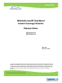
Release Notes MobileAccessVE Dual-Band Instant Coverage Solution Release Notes VCU Version 2.6 VAP Version 2.6 REV: A03 Date: OCT 2010 © Copyright 2010, MobileAccess Networks Inc. All Rights Reserved. This document contains confidential and proprietary information of MobileAccess and may not be copied, transmitted, stored in a retrieval system or reproduced in any format or media, in whole or in part, wit hout the prior written consent of MobileAccess. MobileAccess reserves the right to alter the equipment specifications and descriptions in this publication wit hout prior notice. No part of this publication shall be deemed to be part of any contract or warranty unless specifically incorporated by reference into such contract or warranty. RN_VE Dual-Band_CE0001101_REV A03_07OCT10.doc General 1 Ge neral The MobileAccessVE Dual-Band solution provides enhanced, cost effective, in-building coverage for any enterprise environment. This Solution is quickly and easily deployed using the existing cable infrastructure to provide instant coverage without effecting existing LAN ser vices or performance. MobileAccessVE minimizes disruption w hile providing a scalable and flexible solution at a significantly lower total installation cost. This document contain important information about the MobileAccessVE Dual- Band Instant Coverage Solution. Please refer to the "MobileAccessVE Dual-Band User Manual" and "MobileAccessVE Dual-Band Quick Installation Sheet" for important information on both installation and operation. List of Acronyms Abbreviation Descr ipt ion DB Dual-Band PoE Power Over Ethernet SME Small / Medium Enterprise STP Shielded Twisted Pair UTP Unshielded Twisted Pair VAP VE Access Pod VCU VE Control Unit UMTS Universal Mobile Telecommunications System EGSM Extended Global System for Mobile Communications PCS Personal Communications Service DCS Digital Cellular System MobileAccessVE Dual-Band Instant Coverage Solution Release Notes 2 Released Components 2 Release d Co mpo ne nts 2.1 Released HW Modules VE Control Units (VCUs) VCU-EGSM-UMTS-12E - VE Control Unit for EGSM/UMTS bands, 12 ports VCU-DCS-UMTS-12E - VE Control Unit for DCS/UMTS bands, 12 por ts VCU-CELL-PCS-12E - VE Control Unit for CELL/PCS bands, 12 ports VE Access Pods (VAPs) 2.2 VAP-EGSM-UMTSE - VE Access Pod for EGSM/UMTS bands VAP-CELL-PCSE - VE Access Pod for CELL/PCS bands VAP-DCS-UMTSE - VE Access Pod for DCS/UMTS bands Released SW Components VE Control Unit (VCU) SW Version 2.6 (for EGSM-UMTS VCU, DCS-UMTS VCU and CELL-PCS VCU) VE Access Pod (VAP) SW Version 2.6 (for EGSM-UMTS VAP, DCS-UMTS VAP and CELL-PCS VAP) Dual-Band MobileAccessVE Instant Coverage Solution Release Notes 3 Solution Highlights 3 Solutio n Hi ghlights The MobileAccessVE Dual-Band solution provides enhanced, cost effective, in-building wireless coverage. This solution is easily deployed using the existing cable infrastructure to provide instant coverage without effecting existing LAN ser vices or performance. VE minimizes disruption while providing a scalable and flexible solution at a significantly lower total installation cost. The MobileAccessVE solution consists of the following main components: VE Control Unit (VCU) - Interfaces with the RF sources and VAPs. It combines the wireless services and the Ethernet service, distributing them to VAPs over CAT-5e/6 cables. Each VCU can support up to 12 VAPs and coverage can be expanded by connecting up to 12 Slave VCUs. Each VCU can ser ve as either Master or Slave depending on its connections. VE Access Pods (VAPs) – Distribute wireless ser vices and provides Ether net/IP connectivity and PoE pass-through to connected IP appliances, such as Wi-Fi APs and IP Phones. VAPs are distributed at strategic locations, over one or more floors, and plug into RJ-45 jacks, which are connected to the VCU via exiting CAT-5e/6 infrastr ucture. VAPs are remotely powered by the VCU utilizing PoE, eliminating the need for local powering. The MobileAccessVE solution pr ovides the following main features and benefits: Low Deploy ment Cost – The MobileAccessVE system can be deployed over existing CAT5e/6 cabling infrastr ucture and existing Ethernet jacks. The VE system seamlessly coexists with the Enterprise LAN and does not consume LAN capacity. VAPs are remotely powered using Power-over-Ethernet (PoE) eliminating the need for local powering. Simple and Fast Installat ion - The system is simple to install, and can be deployed in a few hours, with minimum disturbance to the enter prise. VAPs are provided with integrated internal antennas. (External antennas can also be used for special coverage requirements). Auto Configurat ion of Slave VCUs and VAPs - The Master VCU auto-discovers the Slave VCUs and VAPs, performs cable adj ustment to each unit individually, and configures it to provide required service. This process is done automatically without user intervention. Flexible Select ion of Capacity Source – BTS, Picocells, Femtocells and BDAs. Minimum Macro- networ k Impact - With low power distributed coverage. Flexible and Scalable Architecture - Ease of expansion provides “pay as you grow ” scalability. The system can be deployed in a single-tier configuration (Master VCU and up to 12 VAPs) and easily expanded to a multi-tier configuration by adding Slave VCUs and additional VAPs. T he Master VCU has the same HW and SW as the Slave VCU and they are auto-configured to act as either Master or Slave according to the actual cabling connections. Carrier- Grade Management - Remote monitoring and configuration using a standard web browser and S NMP. T he Master VCU provides a central interface for managing the entire deployment, including Slave VCUs and VAPs. The VE system can seamlessly integrate into Fault Management system that suppor ts SNMP events. The VCU provides output alarms that can be connected to the auxiliary input of the Base Station or other dr y-contact application. Kentrox’s Extend PDM - The VE deployment can be monitored using Kentr ox’s Extend Polled Device Monitoring (PDM) system for in-building system monitoring. Remote SW Download - VCUs and VAPs can be upgraded remotely via the web GUI, eliminating truck rolls when SW update is desired. Simply dow nload the SW images to the VCU and distribute from VCU to connected VAPs. MobileAccessVE Dual-Band Instant Coverage Solution Release Notes 4 Version Highlights 4 Versio n Hi ghli ghts Version 2.6 introduces the following main features: Support for “Mixed Mode” deploy ment – VAPs can now be connected directly to the master VCU in multi-tier configuration (together with Slave VCUs), allowing to pr ovide coverage on the floor where the master VCU is installed (or on adjacent floors) directly from the master without requiring an additional slave VCU. This is illustrated in the following figure: Enhanced management wit h “Baseline” feature – The VE Web Access Application includes a Baseline feature providing an indication on networ k elements (VCUs/VAPs), which were disconnected from the VE networ k. Connected VCUs and VAPs are automatically added to the Baseline upon detection, and will appear in the topology as grayed out in case they are disconnected. Disconnected unit can be manually removed from the baseline, so that it no longer appears in the networ k topology, via the web GUI. Root Master VCU – First Level VAP – Second Level Disconnected Unit IP recovery tool – An external windows application allowing to recover (display and change) the IP parameters of the VCU by connecting to the RS -232 port of the VCU. MobileAccessVE Dual-Band Instant Coverage Solution Release Notes 5 Important Notes 5 I mportant Notes This section highlights important functional considerations and behavioral aspects of the MobileAccessVE system: Note 1. VCU IP Address and Subnet Mask 2. 3. Upgrading the SW to version 2.6 Connecting VAPs and Slave VCUs to the Same Master VCU 4. Maximum Expected Pin 5. 6. 7. 8. 9. Data Displayed in Web GUI Screens VCU HW Reset Button Maximum Number of VAPs Cables between VCU and Ether net Switch Cable between VAP and Ether net Appliance 10. Web GUI of Slave VCU 11. 12. 13. 14. Web GUI of Slave VCU SNMP Configuration Screen in Web GUI VCU LED Indications in GUI Location Level Index in SNMP 15. SW Download 16. SW Download Descr ipt ion VCU is preconfigured with default IP address: 192.168.1.1 / Default mask: 255.255.255.0. It is advised to assign the VCU a r outable IP address to facilitate remote management using standard web browser and SNMP. No validity check is implemented in this release on subnet mask – take care to only use legal subnet masks. DHCP configuration is not supported in this release. When upgrading the SW to version 2.6, first upgrade all VAPs and only after VAPs are upgraded upgrade the VCUs. [Please refer also to note 16 below]. Connecting both VAPs and VCUs to the same VCU is suppor ted in this version. All units (VCUs and VAPs) must use version 2.6 or above for this configuration. The Maximum Expected Pin is set as default to +33dBm. Set The Maximum Expected Pin according to maximum expected power level from your capacity source (BTS/BDA). WARNING: DO NOT apply to VCU RF inputs power levels exceeding the configured Maximum Expected Pin by more than 15dB. Depending on the size of the deployment, it may take 5-30 seconds for the web GUI screen to update after changing parameters. The change itself takes effect immediately. VCU HW reset button is not active in this release. When the total number of VAPs in the deployment exceeds 72, consult with MobileAccess support. The cables connecting the VCU to the Ether net switch should not be longer than 5m. The cable connecting the VAP to the Ethernet appliance should not be longer than 5m. When locally connecting to a specific Slave VCU, only the VAPs connected to this VCU can be monitored. To monitor the entire deployment, connect to the GUI of the Master VCU. When locally connecting to a specific Slave VCU, alarm status of the VCU may be displayed incorrectly. Connect to Master VCU to monitor system status. In rare occasions, buttons of SNMP configuration screen in the web GUI are not displayed. In such cases, please refresh the screen. The LED indications presented in the GUI (on the VCU picture) are not fully operational. Use icon color in the topology tree as an alterna tive for a quick view of system alarm status. vcuLocationLevelIndex and vapLocationLevelIndex are from 1-13, w here 1 relates to the unit itself and 2-13 relates to ports 1-12 in the VCU. When per forming a remote SW dow nload to the VCU, locate the SW image files on the local hard drive of the PC. Downloads from a networ k path are not suppor ted in this release. In installations with Slave VCUs, a session should be opened to the IP address of the Slave VCU in order to upgrade the SW of the Slave VCU and associated VAPs. MobileAccessVE Dual-Band Instant Coverage Solution Release Notes 6 Note 17. SW Distribution to VAPs 18. SW Distribution to VAPs 19. SW Distribution to VAPs 20. Adjustment Alarm 21. Cable Performance 22. 23. 24. 25. Coexistence with LAN Using PoE External Antenna Option Monitor, Setup and Help Screens Events and Syslog Screens Descr ipt ion During the SW distribution process from VCU to VAPs, ser vice may be interrupted. It is advised to perform the SW download and distributio n in a maintenance window scheduled at off-peak hours. The SW distribution process takes 3-5 minutes. During the distribution process DO NOT perform configuration changes or connect/disconnect VAPs. It is required to reset the VAPs to complete the distribution process, and/or after swapping between VAP SW images. The VCU and all VAPs will restar t automatically to complete the distribution/swap process. An Adjustment Alarm is raised when a VAP or Slave VCU is connected over a cable exceeding system cable length limitation. T he system continues to provide wireless services, but you should check VAP coverage (as output power may be degraded due to excess cable loss) and Ether net connection (as Ether net standard maximum cable length is probably exceeded). (This alarm is not applicable in the Master VCU). The VE system is designed to operate with full performance over typical CAT -5e cables up to 100m length. As there may be a significant variance in cable actual performance, an Adjustment Alarm may also be triggered when connecting on a cable shorter than 100m, indicating that this cable has excess loss that may be degrading system output power. In the current release only “alter native A” PoE is suppor ted. Support for “alternative B” PoE is planned as a future enhancement. If this is required consult MobileAccess. By default, the VAP is set to transmit through the integrated internal antennas. To use external antennas, select the “External Antenna” option for the VAP in the GUI. Monitor, Setup, and Help screens are not implemented in this release. Events and Syslog screens are not implemented in this release. MobileAccessVE Dual-Band Instant Coverage Solution Release Notes 7 Infrastructure Requirements 6 Infrastruct ure Re quire me nts Ether net standards specify that the maximum distance between an Ether net switch and appliance (computer, WLAN AP, etc.) should not exceed 100m (300ft). Therefore, w hen VE shares the IT LAN, the maximum distance for a given cable run cannot be longer than 100 m (300ft) between the Ethernet switch and appliance. This includes all patch cor ds (from switch to VCU, from VCU to patch panel, from RJ-45 outlet to VAP, and from VAP to appliance). Typically the horizontal cabling system will be connected to patch-panels in the communication rooms. The entire cabling system, including the patch panels and patch cords should adhere to the CAT-5e/6 standard. Specifically all pairs of the CAT-5e cable should be wired in the patch panels and patch cords. Infrastructure Requirements: 1. IDF/Telco closet space for one or more VCUs depending on the number and locations of the installed VCUs: (48.3cm x 51.3cm x 8.88cm) per VCU. Note: When planning the IDF/Telco shaft, take the RF equipment (picocell/microcell or BDA) and the VCU in to consideration. 2. 350 Watts of AC power to the VCU IDF/Telco closet. 3. Building infrastructure: CAT-5e/6 cabling, Unshielded or Shielded Twisted Pair (UTP/STP). 24 AWG minimum diameter for CAT-5e cabling. Dedicated CAT-6/7 STP cable from Master VCU to Slave VCUs with run lengths NOT exceeding 100m (300ft) and no shorter than 10m. CAT-5e/6 UTP or STP cable from VCU to each VAP with run lengths NOT exceeding 100m (300ft) and no shorter than 10m (33ft). VAPs can be connected over existing CAT 5e/6 cabling infrastr ucture and existing Ethernet jacks without affecting the LAN. Note: Verify with the IT department that the existing cables support the VE installation. If infrastructure documentation is available, review it to determine cable types and lengths. If the cable information is not available, attempt to visually identify the cable type (depending on the cable vendor, the cable type may be listed on the cable sheath). It is recommended to use a Fluke cable tester to measure the cable length of the most remote VAPs. MobileAccessVE Dual-Band Instant Coverage Solution Release Notes 8 Coverage Guidelines 7 Coverage Guide li nes The maximal coverage area of each VAP is affected by the density and type of environment to be covered. This section provides information on coverage criteria in various types of environments: Standard Env ironment: A traditional office environment with offices, hallways, and scattered cubicles. Open Env ironment: Environment with minimum of obstacles ( i.e. walls). This type of space can be a large conference or meeting room, cubical areas, lobby, or atrium. Dense Environment: A dense environment consists of a relatively large amount of walls, offices, equipment, tall file cabinets, bookshelves, and other items that could potentially impact the wireless signal. Examples for this type of environment are dense offices, hospitals, and manufacturing spaces. Coverage guidelines herein are conser vative “rule of thumb” estimates of RF cove rage per VAP, meant to be used in scenarios in which detailed designs are not performed. When the coverage layout is designed, the coverage per VAP is expected to increase by up to 33%. Coverage estimates in this section assume 25% overlap between the coverage areas of neighboring VAPs to ensure robust, full coverage thr oughout the enterprise with no “dead zones”. Dense Envir onment Open Envir onment Standard Envir onment Band PCS PCS UMTS Technology Downlink Frequency CDMA or GSM WCDMA WCDMA 1900 MHz 1900 MHz 2100 MHz Spacing between VAPs 128 feet (39 m) 120 feet (36 m) 90 feet (27.5 m) 12,750 sqft (1,185 sqm) 90 feet (27.5 m) 25,425 sqft (2,362 sqm) 67 feet (20.5 m) 11,250 sqft (1,045 sqm) 83 feet (25 m) 21,350 sqft (1,983 sqm) 64 feet (19.5 m) 6,300 sqft (585 sqm) 67 feet (20.5 m) 14,250 sqft (1,324 sqm) 57.5 feet (17.5 m) 14,250 sqft (1,324 sqm) 12,750 sqft (1,185 sqm) 10,425 sqft (969 sqm) Coverage per VAP Spacing between VAPs Coverage per VAP Spacing between VAPs Coverage per VAP In areas with combinations of environments of various densities, place the VAPs on the border between the different types of areas, closer to the denser area. The coverage guidelines in the table above are provided for the higher frequency bands (UMTS and PCS). The lower frequency bands (DCS, EGSM and CELL) are omitted from the table because coverage in these bands will be better than that of the higher frequency bands. The coverage of a dual-band system will be determined by the higher frequency band (i.e. PCS for CELL/PCS and UMTS for EGSM/UMTS and DCS/UMTS). MobileAccessVE Dual-Band Instant Coverage Solution Release Notes 9 Kentrox’s Extend PDM System for In-building System Monitoring 8 Kentro x’s Extend PDM Syste m for I n-buildi ng Syste m Mo nitoring This release introduces the support for monitoring the MobileAccessVE deployment using Kentrox’s Extend Polled Device Monitoring (PDM) system for in-building system monitoring. This solution utilizes the S NMP protocol to monitor alarms, including polling alarms on the MobileAccessVE devices. The following are prerequisites for integration with Kentrox’s PDM solution: • Kentrox Extend PDM system with software license for monitoring "type-B" systems. • Kentrox Extend PDM software version 3.40 or newer. • Extend PDM Device Definition File, generated by Kentrox. • VCU version 2.4 or newer. • IP connectivity between the VE Master VCU and the Kentrox server (e.g. via a wireless modem). Please consult MobileAccess or Kentrox for necessary hardware or software components and suppor t: Kentrox MobileAccess Joel Tamkin – Product Manager [email protected] +1 (614) 923-1242 Tech Suppor t [email protected] +1 (800) 787-1266 Tech Suppor t suppor [email protected] +1 (800) 733-5511 MobileAccess 8391 Old Courthouse Road, Suite 300, Vienna, VA 22182 Tel: +1(866)436-9266, +1(703)848-0200 TAC: +1(800)787-1266, Fax: +1(703)848-0280 http://www.MobileAccess.com MobileAccessVE Dual-Band Instant Coverage Solution Release Notes 10