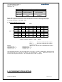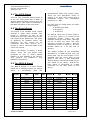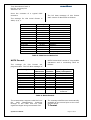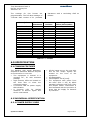
1
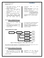
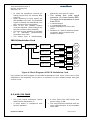
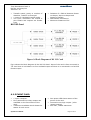
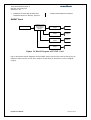
Operation Manual
TIME DISTRIBUTION RACK - 4
Masibus Automation And Instrumentation Pvt. Ltd.
B/30, GIDC Electronics Estate,
Sector-25, Gandhinagar-382044, Gujarat, India
Ph: 91 79 23287275 - 79
Fax: 91 79 23287281, 82
Email: [email protected]
Web: www.masibus.com
masibus
Time Distribution Rack-4
Ref No: m03/om/101
Issue No: 02
02
(6) SPECIFICATION
6.1 Common Features
6.2 Individual Specification
6.2.1 Power Supply Card
6.2.2 1PPS/IRIG B TTL Card
6.2.3 IRIG B Modulation Card
6.2.4 RS-232 Card
6.2.5 EVENT Card
03
Figures & Tables
Contents
(1)INTRODUCTION/OVERVIEW
1.1 Purpose of the Manual
1.2 Product Overview / Description
(2) SAFETY / WARNING
PRECAUTIONS
2.1 Safety Precautions
2.2 Warning Precautions
(3) FRONT AND REAR PANEL
PICTURE
04
3.1 Front Panel
3.2 Rear Panel
3.3 Mounting Detail
(4) USER CONFIGURATION
06
4.1 Switch Selection
4.2 Default Relay Input Condition
4.3 Panel Switching Logic
(5) COMMUNICATION DETAILS
5.1
5.2
5.3
5.4
The 1PPS Signal
The EVENT Signal
IRIG-B Signals
RS-232 Outputs
Operator’s Manual
09
12
Front Panel of TDR-4
Back Panel of TDR-4
Input Panels of TDR-4
Mounting Detail of TDR-4
Switch Selection
IRIG B Modulated Signal
Block Diagram of 1PPS/IRIG
B TTL Card
Figure8: Block Diagram of IRIG B
Modulation Card
Figure9: Block Diagram of RS 232
Card
Figure10: Block Diagram of EVENT
Card
Figure1:
Figure2:
Figure3:
Figure4:
Figure5:
Figure6:
Figure7:
Table
Table
Table
Table
Table
1:
2:
3:
4:
5:
Switch Selection
IRIG B Code Sequence
RMC Record Selection
NGTS Format
T Format
Page 1 of 17
04
04
05
05
06
10
13
14
15
16
07
10
11
11
12
masibus
Time Distribution Rack-4
Ref No: m03/om/101
Issue No: 02
Note: Information in this manual is
subject to change without
notice or permission.
prior
Warning Symbol
The symbol calls attention to the
operating procedure, practice or the like
which if not correctly performed or
adhered to , could result in personal
injury or damage to or destruction of
part or all of the product and system. Do
not proceed beyond a warning symbol
until the indicated condition are fully
understood and met.
Class-2
Type
of
Instrument
Note: Class-2 – Instrument is
using Line & Neutral for
Power Supply Input.
1. INTRODUCTION
1.1. Purpose of The Manual:
How to read this manual???
Installer: Read Chapters 1, 3, 4.
System Designer and New User:
Read All Chapters
Expert User: Read Chapters 3, 4, 5, 6.
Regarding This User’s Manual
→ This manual should be provided to
the end user. Keep an extra copy or
copies of the manual in a safe place.
→ Read this manual carefully to gain a
thorough understanding of operating this
product before starting operation.
Operator’s Manual
→ This
manual
describes
the
functions of this product. Masibus
does not guarantee the application of
these functions for any particular
purpose.
→ Under
absolutely
no
circumstances may the contents of
this manual, in part or in whole, be
transcribed
or
copied
without
permission.
1.2. Product Over
Description:
View
/
→ Time Distribution Rack-4 (TDR-4)
is an analog system that accepts
signals like 1PPS, IRIG-B TTL, IRIG-B
Modulated and RS-232 from GPS
Clock Product and gives four number
of isolated outputs of each signal
same as input.
→ TDR-4 is housed in a 19’’, 3U
rack mounted package. It has nine
output card slots and one supply
card slot.
→ There are five different types of
output cards 1PPS, IRIG-B TTL, RS232,
EVENT
and
IRIG-B
MODULATION. Any signal card can
easily be inserted into any signal
card slot excluding Power Supply
Slot.
→ If user requires more than four
signal outputs of any signal, user has
to insert two or more respected
signal output cards in signal card
slots as per the requirement.
→ TDR-4 has also facility to
interface
redundant
GPS
Clock
product incases of any failure occur
with the first GPS Clock.
Page 2 of 17
Time Distribution Rack-4
Ref No: m03/om/101
Issue No: 02
masibus
2. SAFETY /
WARNING
PRECAUTIONS
and local codes and regulations. Wiring
must be suitable for voltage, current,
and temperature rating of the system.
2.1. Safety Precautions
→ Beware not
terminal screws.
Dangerous
voltages
capable
of
causing
death
are
sometimes
present in this instrument. Before
installation or beginning of any
troubleshooting
procedures
the
power to all equipment must be
switched off and isolated. Units
suspected of being faulty must be
disconnected and removed first and
brought to a properly equipped
workshop for testing and repair.
Component
replacement
and
interval adjustments must be made
by a company person only.
2.2. Warning Precautions
→ Before wiring, verify the label for
correct model number and options.
→ Wiring must be carried out by
personnel, who have basic electrical
knowledge and practical experience.
→ It is recommended that power of
these units to be protected by fuses,
circuit breakers or external over current
rated at the minimum value possible.
to
over-tighten
→ Verify that the ratings of the output
devices and the inputs as specified in
Chapter 6 are not exceeded.
→ Upon receipt of the shipment remove
the unit from the carton and inspect the
unit for shipping damage. If any damage
due to transit, report and claim with the
carrier. Write down the model number
and serial number for future reference
when corresponding with our Customer
Support Division.
→ Do not use this instrument in areas
such as excessive shock, vibration, dirt,
moisture, corrosive gases or rain. The
ambient temperature of the areas should
not
exceed
the
maximum
rating
specified.
→ Provide power from a single-phase
instrument power supply. If there is a lot
of noise in the power line, insert an
insulating transformer into the primary
side of the line and use a line filter on
the secondary side. As counter measures
against noise, do not place the primary
and secondary power cables close to
each other.
→ All wiring must be confirmed to
appropriate standards of good practice
Operator’s Manual
the
Page 3 of 17
masibus
Time Distribution Rack-4
Ref No: m03/om/101
Issue No: 02
3.0 FRONT AND REAR PANEL PICTURE
3.1 FRONT PANEL
Figure 1: Front Panel of TDR-4
TDR-4 is housed in a compact 19’’, 3U
rack mounted package.
facilitated with the provision of direct
24V DC supply on demand by customer.
Figure 1 shows the front panel of the
Time Distribution Rack. There are
different five types of output cards
available which are 1PPS, IRIG-B TTL,
IRIG-B MODULATION, EVENT and RS232.
Each card has one LED which shows the
power status of the card and four
numbers of isolated outputs with its
status LED which shows the status of the
signal.
There is also one card for the power
supply of the TDR-4. TDR-4 can take
power from the main (230 V AC) by
Allied standard connector with fuse, filter
and On/Off switch. Instrument is also
If user requires more than four number
of outputs then user has to insert
another same type of the card in any
slot of the TDR-4, thus user has
maximum 36 outputs of one signal if all
the nine cards are same type.
3.2 REAR PANEL
A–> L/+
B–> E
C–>N/-
85V TO 265V AC
120V TO 370VDC
Figure 2: Back Panel of TDR – 4
Operator’s Manual
Page 4 of 17
masibus
Time Distribution Rack-4
Ref No: m03/om/101
Issue No: 02
Panel – 2
Panel – 1
Figure 3: Input Panels of TDR-4
The different inputs are connected to the
back panel of the TDR-4. Back panel has
also different jumper for the output
selection.
There are two input panels available for
user. The inputs are 1PPS, IRIG-B TTL,
IRIG-B modulated and RS-232 and also
POWER, GPSLOST, WATCHDOG and two
EVENT contacts available as inputs
which are the outputs of the GPS Clock.
connected to it are directly given to the
different cards inserted in the TDR-4 in
case of only one GPS Clock is connected.
TDR-4 has facility to connect redundant
GPS Clock with TDR-4. TDR-4 selects
one of the Two GPS and takes all the
signals of that GPS as input and gives
that signal to the different cards for
further distribution of the signals. The
selection of the GPS is based on different
inputs given by the GPS.
The input panel - 1 which is near to the
fan is the default panel and inputs
3.3 MOUNTING DETAIL
m a sib u s
Figure 4: Mounting Detail of TDR-4
4.0 USER CONFIGURATION
Operator’s Manual
Page 5 of 17
masibus
Time Distribution Rack-4
Ref No: m03/om/101
Issue No: 02
4.1 SWITCH SELECTION
Figure 5: Switch Selection
Figure 5 shows the lay out of the Switch available at the back plate of the TDR-4. The
configuration of each jumper is as shown below.
Use
Switch
Panel No
Name
SW10 is used to select the mode of the TDR-4.
SW10_1 OFF and SW10_2 ON for without Redundant I/Ps TDR.
SW 10
SW10_1 ON and SW10_2 OFF for with Redundant I/Ps TDR.
BOTH
CHANNLE
J19 & J20 is used to use 1PPS as PFC output. This output is
available as an EVENT so user has to insert EVENT card to use this
J19 &
output.
J20
Short pin 1 and 2 for 1PPS as PFC.
Short pin 2 and 3 for normal Event output.
SW1 & SW7 are used to select inverted or non inverted logic of the
POWER 1 input.
SW1 &
SW7
SW1_1 ON and SW1_2 OFF for inverted logic for POWER 1 input
and SW7_1 OFF.
SW1_1 OFF and SW1_2 ON for non inverted logic for POWER 1
input and SW7_1 ON.
SW2 & SW7 are used for inverted or non inverted logic of the
WATCHDOG 1 input.
Channel - 1
SW2 &
SW7
SW2_1 ON and SW2_2 OFF for inverted logic for WATCHDOG 1
input and SW7_2 OFF.
SW2_1 OFF and SW2_2 ON for non inverted logic for WATCHDOG
1 input and SW7_2 ON.
SW3 & SW8 are used for inverted or non inverted logic of the GPS
LOST 1 input.
SW3 &
SW8
SW3_1 ON and SW3_2 OFF for inverted logic for GPS LOST 1 input
and SW8_1 OFF.
SW3_1 OFF and SW3_2 ON for non inverted logic for GPS LOST 1
input and SW8_1 ON.
Channel - 2
Operator’s Manual
SW4 &
SW8
SW4 & SW8 are used to select inverted or non inverted logic of the
POWER 2 input.
Page 6 of 17
masibus
Time Distribution Rack-4
Ref No: m03/om/101
Issue No: 02
SW4_1 ON and SW4_2 OFF for inverted logic for POWER 2 input
and SW8_2 OFF.
SW4_1 OFF and SW4_2 ON for non inverted logic for POWER 2
input and SW8_2 ON.
SW5 & SW9 are used for inverted or non inverted logic of the
WATCHDOG 2 input.
SW5 &
SW9
SW5_1 ON and SW5_2 OFF for inverted logic for WATCHDOG 2
input and SW9_1 OFF.
SW5_1 OFF and SW5_2 ON for non inverted logic for WATCHDOG
2 input and SW9_1 ON.
SW6 & SW9 are used for inverted or non inverted logic of the GPS
LOST 2 input.
SW6 &
SW9
SW6_1 ON and SW6_2 OFF for inverted logic for GPS LOST 2 input
and SW9_2 OFF.
SW6_1 OFF and SW6_2 ON for non inverted logic for GPS LOST 2
input and SW9_2 ON.
Table 1: Switch Selection
4.2 Default Relay Input Condition
There are two ways of configuring Relay Input terminals at TDR-4 back Plate, i.e. noninverting mode and inverting mode. The relay input terminals for Panel-1 and Panel-2
are POWER-1, GPS LOST-1, WATCHDOG-1 and POWER-2, GPS LOST-2, WATCHDOG-2
respectively.
In non-inverting mode if these terminals get shorted by Relay contacts the TDR-4
indicates fault condition. For example if GPS clock lost the GPS connection and activates
its GPS LOST output Relay and thus the GPS LOST-1 terminal gets connected, the TDR-4
in non-inverting mode will glow LED of GPS LOST-1 in front of Power Supply card.
The default relay condition of GPS clock for non-inverting mode of TDR-4 is expected as
below
Relay
Condition NO/NC
Power
NO (Power ON)
NC (Power OFF)
NO (Watchdog
NC (Watchdog Reset
Watchdog
Reset Not
Available)
Available)
NO (GPS signal
GPS Lost
NC (GPS signal Lost)
Healthy)
For inverting Mode operation of TDR-4 Relay inputs there is switch settings as shown in
Table-1. In inverting mode the relay input terminals are opened for fault LED indication.
For example if GPS clock lost the Power, so at this condition the POWER-1 terminals
should be opened to indicate fault LED at front of Power Supply card.
The default relay condition of GPS clock for inverting mode of TDR-4 is expected as
below
Operator’s Manual
Page 7 of 17
masibus
Time Distribution Rack-4
Ref No: m03/om/101
Issue No: 02
Relay
Power
Watchdog
GPS Lost
Condition NO/NC
NO (Power OFF)
NC (Power ON)
NO (Watchdog
NC (Watchdog Reset
Reset Available)
Not Available)
NO (GPS signal
NC (GPS signal
Lost)
Healthy)
Note: The relays of GPS clock are made wet by 5V DC from TDR-4 Relay Input
Terminals. Therefore extensive care must be taken while connecting Relay input
terminals of TDR-4 to any GPS clock.
4.3 Panel Switching Logic
ABC
DEF
000
001
011
010
100
101
111
110
000
X
X
X
X
X
X
1
1
001
X
X
X
X
X
X
1
1
011
X
X
X
X
X
X
1
1
010
X
X
X
X
X
X
1
1
100
X
X
X
X
X
X
1
1
101
X
X
X
X
X
X
1
1
111
0
0
0
0
0
0
0
0
110
0
0
0
0
0
0
1
0
Result of above map S2 = (AB)’ + DEFC’
Where
APower On – 1
BWatch Dog – 1
CGPS Lost – 1
S2 = 0
Panel 1 is selected for output
S2 = 1
Panel 2 is selected for output
X= Don’t care
*When relay is open it is considered as logic 1.
DPower On – 2
EWatch Dog – 2
FGPS Lost – 2
For Example if Panel-1 has inputs A,B and C at logic 1,1 and 0 respectively and Pannel-2
has inputs D,E and F at logic 1,0 and 0 the equation S2 = (AB)’ + DEFC’ will result in 0
and thus the Inputs at Panel-1 will be forwarded to TDR-4 outputs.
5.0 COMMUNICATION DETAIL
Operator’s Manual
Page 8 of 17
masibus
Time Distribution Rack-4
Ref No: m03/om/101
Issue No: 02
synchronized 1PPS time output pulse.
There are two alternative forms of
output, a dc level shift output, and a
modulated output. The modulation
frequency is 1 KHz.
5.1 The 1PPS Signal
This is a very important timing signal. It
is the TTL level pulse with a width of
200ms isolated output coming from the
GPS receiver. This 1PPS is connected to
the BNC connector on the rear panel.
For each form of output there are three
output codes:a. A Reference Mark
b. A logical 1
c. A logical 0
5.2 The Event Signal
The signal is an isolated event output
through a static relay contact. This
signal is connected to two of the
terminal of the 8 way barrier strip on the
rear panel of the Instrument. The event
is assigned as isolated event; the
frequency for this event can be
configured from GPS receiver as 1
minute or 1 hour. The pulse width of the
event is 2 second.
For IRIG-B, each one of these codes is
10 ms long, which is 10 cycles for the
modulated format. There are 100
possible codes per time frame, although
not all of them are used. The code
sequence is shown in Table 1, and the
waveforms shown in Figure 2. The day
number starts at 1 on the first of
January.
TDR-4 has facility of taking 2 Event
inputs. There are two Event input
terminals at rear of TDR-4 named
EVENT-1-1 and EVENT1-2 for Panel-1
and similarly for
EVENT-2-1 and
EVENT2-2 for Panel-2.
The output voltage of the modulated
waveform is 3 V peak to peak into a 50
ohms load. The dc level output is TTL
standard and the rising edge of the
pulse is "On Time". 1 kHz modulated
IRIG-B signal is connected to BNC on the
rear panel of the device. IRIG-B TTL
level signal is connected to a BNC
connector on the rear panel of the
device.
5.3 The IRIG-B Signal
The IRIG-B format is a serial format
based on a message frame per second
which
is
Co-ordinate
with
the
Position
Type
0
1
2
3
4
5
6
7
8
9
10
11
12
13
14
15
Reference Mark
Signal
Signal
Signal
Signal
Logical 0
Signal
Signal
Signal
Reference Mark
Signal
Signal
Signal
Signal
Logical 0
Signal
Operator’s Manual
Item
Digit
Seconds
Seconds
Seconds
Seconds
1
2
4
8
Seconds
Seconds
Seconds
10
20
40
Minutes
Minutes
Minutes
Minutes
1
2
4
8
Minutes
10
Position
Type
27 to 28
29
30
31
32
33
34
35
36
37
38
39
40
41
42 to 48
49
Logical 0
Reference Mark
Signal
Signal
Signal
Signal
Logical 0
Signal
Signal
Signal
Signal
Reference Mark
Signal
Signal
Logical 0
Reference Mark
Item
Digit
Day
Day
Day
Day
1
2
4
8
Day
Day
Day
Day
10
20
40
80
Day
Day
100
200
Page 9 of 17
masibus
Time Distribution Rack-4
Ref No: m03/om/101
Issue No: 02
16
17
18
19
20
21
22
23
24
25
26
Signal
Signal
Logical 0
Reference Mark
Signal
Signal
Signal
Signal
Logical 0
Signal
Signal
Minutes
Minutes
20
40
Hours
Hours
Hours
Hours
1
2
4
8
Hours
Hours
10
20
50 to 58
59
60 to 68
69
70 to 78
79
80 to 88
89
90 to 98
99
Logical 0
Reference Mark
Logical 0
Reference Mark
Logical 0
Reference Mark
Logical 0
Reference Mark
Logical 0
Reference Mark
Table 2 – IRIG B Code Sequence
Figure 6: IRIG B Modulated Signal
5.4 RS-232 Outputs
There are two RS-232 serial ports
equipped within the device. These two
serial ports use two separate high
performance chips to get electrical
isolation. Each serial port has its own
format of the timing strings. On serial
port one, 9 ways D-type socket, the
message is NMEA ($GPRMC) format. The
Operator’s Manual
serial port two, 9 way D-type plug, the
message is NGTS or T-FORMAT.
NMEA Format
RMC RECORD FORMAT
The $GPRMC sentence contains time and
date of position fix, speed and course
information. The following examples
Page 10 of 17
masibus
Time Distribution Rack-4
Ref No: m03/om/101
Issue No: 02
show the contents of a typical RMC
sentence:
The full data message of this format
shall consist of data fields as follows:
The settings for this serial format is
4800, 8, N, 1.
Field
Sentence ID
Example
$GPRMC,
UTC Time
Status
Latitude
N/S Indicator
Longitude
E/W Indicator
Speed over ground
Course over ground
UTC Date
Magnetic variation
Magnetic variation
Checksum
Terminator
Comments
130525.00,
A,
4250.5589,
S,
14518.5084,
E,
000.1,
245.0,
291206,
,
,
*25
<CR><LF>
hhmmss.ss,
A = Valid/V = Invalid,
ddmm.mmmm,
N = North/S = South,
dddmm.mmmm,
E = East/W = West,
Knots,
Degrees,
DDMMYY,
Degrees,
E = East/W = West,
*CC
Non-printing characters
Table 3: RMC Record Selection
NGTS Format
The settings for this format are
programmable. The full data message of
Description
Code Identification
Year in Century
Month
Day of Month
Day of Week
Hours
Minutes
GMT Marker
Validity Marker
CRLF
Number of
Characters
1
2
2
2
1
2
2
1
1
2
NGTS format shall consist of 14 printable
characters and a concluding CRLF as
follows:
Character
Position
1
2,3
4,5
6,7
8
9,10
11,12
13
14
15,16
Range of
Value/Information
Capital T
0 to 99
1 to 12
1 to 31
1 to 7
0 to 23
0 to 59
0 or 1
0 or 1
Non-printing
character
Table 4: NGTS Format
The transmission sequence shall be from
the
Code
Identification
character
through to the CRLF with the most
significant digits being transmitted first.
Operator’s Manual
The message shall become automatically
available at one second prior to the clock
minute epoch.
T-Format
Page 11 of 17
masibus
Time Distribution Rack-4
Ref No: m03/om/101
Issue No: 02
The settings for this format are
programmable. The full data message of
T-format shall consist of 21 printable
Description
Code Identification
Divider
Year in Century
Divider
Month
Divider
Day of Month
Divider
Day of Week
Divider
Hours
Divider
Minutes
Divider
GMT Marker
Validity Marker
CRLF
Number of
Characters
1
1
2
1
2
1
2
1
1
1
2
1
2
1
1
1
2
characters with a concluding CRLF as
follows:
Character
Position
1
2
3,4
5
6,7
8
9,10
11
12
13
14,15
16
17,18
19
20
21
22,23
Range of
Value/Information
Capital T
:
0 to 99
:
1 to 12
:
1 to 31
:
1 to 7
:
0 to 23
:
0 to 59
:
0 or 1
0 or 1
Non printing character
Table 5: T- Format
6.0 SPECIFICATION
6.1 COMMON FEATURES
The Masibus GPS signal distributor
amplifies & distribute different outputs
as connected to it rear side.
• The equipment is housed in a
compact 19’’, 3U rack mounted
package
• High intensity LEDs are located on
the front face to show the
equipment status
• A Common LED for power supply
ON indication
• A
Common
LED
for
ALARM
detection of Source signal and
source instruments
•
•
•
•
All the inputs are on the rear side
and all the output signals are
located on the front of the
equipment.
Hot Swappable.
Consumption: 50 W [max].
The equipment take power from
the main (230 V AC) by Allied
standard connector with fuse, filter
and On/Off switch. Instrument is
also facilitated with the provision of
direct 24V DC supply on demand
by customer.
6.2 INDIVIDUAL SPECIFICATION
6.2.1 POWER SUPPLY CARD
Operator’s Manual
Page 12 of 17
masibus
Time Distribution Rack-4
Ref No: m03/om/101
Issue No: 02
•
•
•
•
•
•
•
Input Supply range 85 - 265 VAC
(wide range) 120 - 370VDC
Frequency 47-440 Hz
Inrush current <18A peak @
115VAC, <36 A peak @230 VAC,
cold start @ 25°C
Input current 1.5A max. (RMS) @
115 VAC
Efficiency 70% typical at full load
Safety
ground
leakage
current
<0.5mA @ 50/60 Hz; 264VAC input
Maximum power 60W for convection;
80W
with
30CFM
forced
air
•
•
•
•
Adjustment
range
-5,
+10%
minimum
Hold-up time 20ms @ 60W load,
115VAC nominal line
Overload protection Short circuit
protection on all outputs.
Compliance: FCC Class B, CISPR22
Class B, EN55022 Class
B, VDE0878PT3 Class B
Isolation of 500VAC Between Power
and Inputs in 85 - 265 VAC supply
range.
6.2.2 1PPS / IRIG B TTL Card
•
•
•
5V TTL input level on BNC, 50Ω
connector.
4 numbers of 5V TTL isolated outputs
level on BNC, 50Ω connector.
4 common LEDs to show the status
of each output.
•
•
•
The input pulse is distributed without
any change in polarity or duration.
Maximum Distance: 10 meters
Isolation of 1.5KV AC between Power
to Output, Input to Output and
Output to Output.
1PPS/IRIG-B TTL CARD
1 PPS / IRIG B
TTL Input
Buffer and
Distribution Circuit
Isolator Circuit
1 PPS1/
IRIGB
TTL 1
Isolator Circuit
1 PPS2/
IRIGB
TTL 2
Isolator Circuit
1 PPS3/
IRIGB
TTL 3
Isolator Circuit
1 PPS4/
IRIGB
TTL 4
Figure 7: Block Diagram of 1PPS / IRIG B TTL Card
Fig.7 shows the block diagram of the 1PPS/IRIG-B TTL card. The input of the card is
buffered by the buffer and then four isolated outputs are provided.
6.2.3 IRIG B MODULATION CARD
•
Time Code Amplifier and distributor
provide analog IRIG B or any other
format, Time code amplification and
Operator’s Manual
distribution. The time codes are
based on a 1 kHz amplitude
modulated (1/3) sine wave carrier.
Page 13 of 17
masibus
Time Distribution Rack-4
Ref No: m03/om/101
Issue No: 02
•
•
•
•
•
In input the equipment receives an
analog signal from an external IRIG
B source.
When detecting an input signal, the
LED SIGNAL turns ON. The amplified
signal is isolated and distributed over
the 4 outputs of the equipment.
Each of the four isolated outputs
could be adjusted. These settings are
the gain of each output amplifier.
The gain of each amplifier is adjusted
by
a
dedicated
potentiometer
accessible from front.
The output level is independently
settled for each type of output.
•
•
•
•
•
The analog time code signal
connector is a base female BNC.
The input circuit impedance is more
than 600 Ω.
1 KHz AM Signal
3:1 Modulation Ratio
Output Impedance is more than
750Ω
Isolation of 1.5KV AC between Power
to Output, Input to Output and
Output to Output.
IRIG B Modulation Card
IRIGB Modulated
Input
Amplifier Circuit
Isolator Circuit
IRIGB
Modulati
on 1
Amplifier Circuit
Gain
Control 1
Isolator Circuit
IRIGB
Modulati
on 2
Amplifier Circuit
Gain
Control 2
Isolator Circuit
IRIGB
Modulati
on 3
Amplifier Circuit
Gain
Control 3
Isolator Circuit
IRIGB
Modulati
on 4
Amplifier Circuit
Gain
Control 4
Figure 8: Block Diagram of IRIG B Modulation Card
Fig.8 shows the block diagram of the IRIG-B Modulation Card. Input of the card is first
amplified by the amplified circuit then it is divided in to four isolated output with gain
control circuit.
6.2.4 RS-232 CARD
•
•
The Time frame distributor allows
ASCII frame distribution on
4 serial tracks in compliance with
RS-232 standard.
Operator’s Manual
•
•
A front fascia One LED shows that
power supply is ON.
The output data are diffused with the
same characteristics of the available
input data.
Page 14 of 17
masibus
Time Distribution Rack-4
Ref No: m03/om/101
Issue No: 02
•
•
•
Transfer speed, parity or number of
data bits, couldn’t be changed.
1 input to 4 isolated outputs mode.
The input connectors are SUB'D 9
pins female and outputs are female
type.
•
•
•
Isolation of 1.5KV AC between Power
to Output, Input to Output and
Output to Output.
DB9 Female Connectors
Maximum Distance of 50’
RS-232 Card
Figure 9: Block Diagram of RS 232 Card
Fig.9 shows the block diagram of the RS-232 Card. Input of the card is first converted in
TTL level then it is divided in to four isolated output and then it is converted in to RS-232
format output.
6.2.5 EVENT CARD
•
•
•
1 input 4 outputs.
Four potential free relay outputs are
available on the front fascia of the
card.
4 LEDs are available which shows the
status of each event.
Operator’s Manual
•
•
•
One power LED shows status of the
power of the card.
Inverted event logic output. (refer
jumper setting)
350 VAC, 120mA maximum
Page 15 of 17
masibus
Time Distribution Rack-4
Ref No: m03/om/101
Issue No: 02
•
Isolation of 2000 MΩ at 500 VDC
between Power to Output, Input to
Output and Output to Output
EVENT Card
EVENT Input
Selection Circuit
for Inverted or
Noninverted
EVENT
Isolator Relay
Output
EVENT 1
Isolator Relay
Output
EVENT 2
Isolator Relay
Output
EVENT 3
Isolator Relay
Output
EVENT 4
Figure 10: Block Diagram of EVENT Card
Fig.10 shows the block diagram of the EVENT Card. Input of the card is first given to
selection and inverter circuit then output of this block is divided in to four isolated
output.
Operator’s Manual
Page 16 of 17