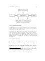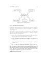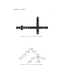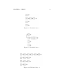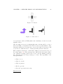
1
The Development and Implementation of A
Domino Game
Yuelong Huang
BSc (hons) Computer Science
University of Bath
May 2005
The Development and Implementation of A Domino Game
Submitted by Yuelong Huang
Copyright
Attention is drawn to the fact that copyright of this dissertation rests with its
author. The Intellectual Property Rights of the products produced as part
of the project belong to the University of Bath (see http://www.bath.ac.uk/
ordinances/#intelprop).
This copy of the thesis has been supplied on condition that anyone who
consults it is understood to recognise that its copyright rests with its author
and that no quotation from the dissertation and no information derived from
it may be published without the prior written consent of the author.
Declaration
This dissertation is submitted to the University of Bath in accordance with
the requirements of the degree of Bachelor of Science in the Department
of Computer Science. No portion of the work in this dissertation has been
submitted in support of an application for any other degree or qualification
of this or any other university or institution of learning. Except where
specifically acknowledged, it is the work of the author.
Signed.........................
This dissertation may be made available for consultation within the University Library and may be photocopied or lent to other libraries for the
purposes of consultation.
Signed.........................
i
Abstract
This project is to develop a system that emulates the game of partnership
domino. The system will allow user to play with three computer players. The
computer players, whose intelligent levels could be varied, will be capable
of playing in a responsive manner. The system will provide a graphical user
interface, which user will perform all tasks upon. The application is named
Badomino, which stands for Bath’s domino.
ii
Acknowledgements
First I would like to thank my project supervisor Dr. Nicolai Vorobjov for
all his support and guidance through the project. I also extend my sincere
thanks and appreciation to my family. I would also like to thank Xin and
Ying for proofreading this dissertation.
iii
Contents
1 Introduction
1
1.1
Scope . . . . . . . . . . . . . . . . . . . . . . . . . . . . . . .
1
1.2
Problems . . . . . . . . . . . . . . . . . . . . . . . . . . . . .
2
1.3
Framework of the dissertation . . . . . . . . . . . . . . . . . .
3
2 Literature Survey
5
2.1
Introduction . . . . . . . . . . . . . . . . . . . . . . . . . . . .
5
2.2
What are dominoes . . . . . . . . . . . . . . . . . . . . . . . .
6
2.2.1
Rules of partnership dominoes . . . . . . . . . . . . .
6
2.2.2
Examples . . . . . . . . . . . . . . . . . . . . . . . . .
7
Strategies and method assumptions . . . . . . . . . . . . . . .
8
2.3.1
Efforts made by Pervin and Michael . . . . . . . . . .
8
2.3.2
Strategies specification . . . . . . . . . . . . . . . . . .
9
2.3.3
Methods for modelling AI . . . . . . . . . . . . . . . .
10
2.3.4
Levels of AI . . . . . . . . . . . . . . . . . . . . . . . .
11
User interface . . . . . . . . . . . . . . . . . . . . . . . . . . .
12
2.4.1
Background . . . . . . . . . . . . . . . . . . . . . . . .
12
2.4.2
Guidelines . . . . . . . . . . . . . . . . . . . . . . . . .
12
Summary . . . . . . . . . . . . . . . . . . . . . . . . . . . . .
13
2.3
2.4
2.5
iv
3 Requirements analysis and specification
15
3.1
Introduction . . . . . . . . . . . . . . . . . . . . . . . . . . . .
15
3.2
Requirements analysis . . . . . . . . . . . . . . . . . . . . . .
15
3.2.1
User requirements analysis . . . . . . . . . . . . . . .
16
3.2.2
Literature survey analysis . . . . . . . . . . . . . . . .
16
3.2.3
Similar system analysis . . . . . . . . . . . . . . . . .
17
Requirements specification . . . . . . . . . . . . . . . . . . . .
19
3.3.1
Functional requirements (FR) . . . . . . . . . . . . . .
20
3.3.2
Non-functional requirements (NFR) . . . . . . . . . .
22
3.3.3
User interface requirements (UIR) . . . . . . . . . . .
23
3.3
4 Design
25
4.1
Introduction . . . . . . . . . . . . . . . . . . . . . . . . . . . .
25
4.2
Overall architecture of the system
. . . . . . . . . . . . . . .
25
4.2.1
System structuring . . . . . . . . . . . . . . . . . . . .
26
4.2.2
Control models . . . . . . . . . . . . . . . . . . . . . .
26
4.2.3
Modular decomposition . . . . . . . . . . . . . . . . .
27
4.3
4.4
4.5
Design solutions
. . . . . . . . . . . . . . . . . . . . . . . . .
29
4.3.1
Images . . . . . . . . . . . . . . . . . . . . . . . . . . .
29
4.3.2
Domino tiles . . . . . . . . . . . . . . . . . . . . . . .
29
4.3.3
Domino chain . . . . . . . . . . . . . . . . . . . . . . .
30
4.3.4
Models of the game . . . . . . . . . . . . . . . . . . .
34
User interface design . . . . . . . . . . . . . . . . . . . . . . .
36
4.4.1
The conceptual model . . . . . . . . . . . . . . . . . .
36
4.4.2
Physical design . . . . . . . . . . . . . . . . . . . . . .
37
4.4.3
Layout of domino chain . . . . . . . . . . . . . . . . .
38
Summary . . . . . . . . . . . . . . . . . . . . . . . . . . . . .
38
v
5 Detailed design and implementation
39
5.1
Introduction . . . . . . . . . . . . . . . . . . . . . . . . . . . .
39
5.2
Overview of the implementation . . . . . . . . . . . . . . . . .
39
5.2.1
Programming language
. . . . . . . . . . . . . . . . .
39
5.2.2
Application framework . . . . . . . . . . . . . . . . . .
39
5.2.3
Ancillary techniques . . . . . . . . . . . . . . . . . . .
41
5.2.4
Implementation process . . . . . . . . . . . . . . . . .
42
Algorithms . . . . . . . . . . . . . . . . . . . . . . . . . . . .
43
5.3.1
Adding a tile into a domino chain . . . . . . . . . . .
43
5.3.2
Layout management of the domino chain . . . . . . .
43
5.3.3
AI modelling . . . . . . . . . . . . . . . . . . . . . . .
44
Non-trivial components . . . . . . . . . . . . . . . . . . . . .
49
5.4.1
Tile naming system . . . . . . . . . . . . . . . . . . .
49
5.4.2
Decide the first player . . . . . . . . . . . . . . . . . .
50
5.4.3
Thread implementation for player . . . . . . . . . . .
52
Interesting implementation techniques with Java . . . . . . .
52
5.5.1
Draw dominoes on the screen . . . . . . . . . . . . . .
52
5.5.2
Domino images . . . . . . . . . . . . . . . . . . . . . .
53
5.5.3
Use of layered pane . . . . . . . . . . . . . . . . . . . .
53
Summary . . . . . . . . . . . . . . . . . . . . . . . . . . . . .
54
5.3
5.4
5.5
5.6
6 System testing
56
6.1
Introduction . . . . . . . . . . . . . . . . . . . . . . . . . . . .
56
6.2
Testing
57
6.3
. . . . . . . . . . . . . . . . . . . . . . . . . . . . . .
6.2.1
An overview of the test plan
. . . . . . . . . . . . . .
57
6.2.2
Component testing . . . . . . . . . . . . . . . . . . . .
57
6.2.3
System testing . . . . . . . . . . . . . . . . . . . . . .
58
6.2.4
Acceptance testing . . . . . . . . . . . . . . . . . . . .
58
Evaluation . . . . . . . . . . . . . . . . . . . . . . . . . . . . .
58
vi
6.4
Summary . . . . . . . . . . . . . . . . . . . . . . . . . . . . .
7 Conclusions
59
60
7.1
Review of the project
. . . . . . . . . . . . . . . . . . . . . .
60
7.2
Future improvements . . . . . . . . . . . . . . . . . . . . . . .
61
A Prototype
65
B Layout management: the algorithm
70
C Test cases
77
C.1 User input . . . . . . . . . . . . . . . . . . . . . . . . . . . . .
77
C.2 Black box testing . . . . . . . . . . . . . . . . . . . . . . . . .
82
D Evaluation
90
D.1 Functional requirements . . . . . . . . . . . . . . . . . . . . .
90
D.2 Non-functional requirements . . . . . . . . . . . . . . . . . . .
93
E User manual
95
E.1 How to play . . . . . . . . . . . . . . . . . . . . . . . . . . . .
95
E.2 Menus . . . . . . . . . . . . . . . . . . . . . . . . . . . . . . .
96
E.3 Controls . . . . . . . . . . . . . . . . . . . . . . . . . . . . . .
97
F Code
98
vii
Chapter 1
Introduction
1.1
Scope
Dominoes are well-known games. However they are not that popular because
of their constraints:
• it might be hard to find enough players willing to play;
• the players might have different levels, which lead to a boring unbalanced game;
• a domino set and a flat table are required;
• counting the sum of ends and the scores are troublesome by hand.
Therefore it is desirable to have a computer program, which can avoid all
these constraints.
Dominoes usually have many local variations, even partnership dominoes
have three. Because the strategies for different variations could be different,
it is necessary to limit one variation in this project. All-Fives is selected
after discussing with the project supervisor. The basic rules of this game
will be described in in section 2.2.1. However variations within the game,
such as winning points1 , number of doubles2 allowing to re-shuffler, will be
changeable for various usability.
1
2
the number of points needed to win in a game
A double is a tile with the same points on each half.
1
CHAPTER 1. INTRODUCTION
1.2
2
Problems
A main problem in this project is how to design a graphical user interface.
The user interface should be a simulation of the game from the real world.
This leads to a series of further considerations. As stated in section 2.2.1,
the layout of domino chain3 should be in a certain format. For example,
doubles should be placed perpendicularly to the end; if one end is near the
edge of the table, the matching tile should turn a corner. In the real world,
human players control the layout. As we know, human are flexible, and they
could make the best decision by considering the current situation. However,
software works exactly as what it is designed to do. The system need to ask
itself in advance if. . .
• the end is a spinner4 , a double or a normal5 ;
• the matching tile6 is a normal or double;
• the matching tile is a double, could it turns to be a spinner or not;
• the matching end is placed vertically or horizontally;
• the matching end is near the edge;
• the matching end is near the other part of the chain, which could cause
overlapping.
Each combination of those situations stated above should be considered
(though some could never happen). Therefore the layout management of
the chain turns to be really complicated.
The other main problem is the computer player modelling. A beginner might
like to play with a “smart” computer player as his partner, and against
two “stupid” computer players as his opponents from being frustrated. A
skilled player may tend to play with three “smart” computer players to
avoid boredom. Thus different levels for computer players are needed in
the system. Each level will apply corresponding scope of strategies. For
example, a “stupid” computer player just plays randomly; a smarter one will
try to score greedily; an even smarter one will play like a human, which will
consider the current situation and apply suitable strategies. Most common
strategies will be given in section 2.3.2.
3
The domino chain is the chain of dominos already placed on the table.
A spinner is the first double laid, it could sprout two new ends.
5
A normal has two distinct halves
6
A tile matches a end if one of the number on either half is the same as the end.
4
CHAPTER 1. INTRODUCTION
1.3
3
Framework of the dissertation
Chapter 1: Introduction
This chapter briefly states the scope and background of the project. Two
main problems are initially considered. And an outline framework as progress
is made through the dissertation.
Chapter 2: Literature Review
This chapter presents the review of literatures in which an in-depth knowledge and background around the areas involved in the project are introduced. These areas include: history of dominoes, basic rules, AI strategies,
AI approaches, and guidelines of Human Computer Interaction (HCI).
Chapter 3: Requirements analysis and specification
This chapter identifies the process of requirements capture and analysis that
was adopted. The section identifies and discusses key requirements, and
focuses particularly upon areas of particular challenge, difficulty or conflict.
An appropriate scoping of desired system is given, Functional and nonfunctional requirements of the system are also specified in this chapter.
Chapter 4: Design
This chapter is one of the most creative parts of the project. It indicates
how the problem is analysed to create a potential solution, and how the
details of the proposed solution are captured using an appropriate method.
It designs the system architecture that will satisfy those requirements which
have been specified. User interface is also detailed designed in this chapter.
Chapter 5: Detailed Design and Implementation
This chapter follows the same approach as the Design chapter, presenting an
overview of the software architecture and a high-level discussion of the implementation process. It reflects on appropriate implementation approaches,
algorithm choices and language choice. This section provides details of the
implementation procedure that were made to construct the domino game
system based on the design given in the chapter 4. This chapter highlights
the areas of the development that are particularly interesting or hard to
implement.
Chapter 6: System Testing
This chapter describes of testing strategies applied and an overview of the
test plan. The modular testing, system testing and system testing are carried
out in this phase and the testing results are documented. The functional
CHAPTER 1. INTRODUCTION
4
and non-functional requirement evaluation results are documented and the
test results are critically analysed as well.
Chapter 7: Conclusions
This chapter includes an overall evaluation of the project.It highlights the
achievements, identifies things that have been done well, notes areas which
could have been done batter or tackled in another way, which leads potential
future improvements if the project is continued.
Chapter 2
Literature Survey
2.1
Introduction
Partnership dominoes are strategy games of incomplete information. A
player only knows the dominoes in his hand and the ones currently on the
table. The total number of different domino game situations which can occur is approximately 1042 (Armanino, 1959). It seems that we cannot store
all possible situations in the memory of a normal PC. To enable a computer
play dominoes with human or by itself, certain artificial intelligence (AI)
and problem solving methods should be applied. Strategy games such as
chess, dominoes and checkers have often been used to test new techniques
in artificial intelligence research.
Another issue is about the representation of the game. The fundamental calculations and algorithms should be implemented separately from the
graphical user interface. The interface is beneficial to be graphical for implementation and usability reasons. Firstly, the implementation of a readable
textual-representation is more difficult in this game; and also, WYSIWYG1
graphical games are more attractive for players.
The core of this project should be the AI modelling of computer players and
user interface issues. The programming skills, project oriented techniques
and software engineering aspects are treated as the foundations. Although
they are time consuming, as long as they are not directly related to AI
modelling or user interface, they will not be discussed in this area.
1
What You See Is What You Get.
5
CHAPTER 2. LITERATURE SURVEY
2.2
6
What are dominoes
Nowadays dominoes are popular games in the European countries and the
America. However, the oldest domino games were invented as early as 1200
A.D. in China (Ken, 1998). They were derived from cubic dice. As a
result, a domino set originally consisted of 21 pieces, which presented any
permutation of two dice. The tiles of a domino set are the same in size and
shape. Each tile has a face and a back. The backs are indistinguishable;
however the faces are unique. The face of a tile is divided into two halves.
Each half has a number presented by dots, from zero to six. The maximal
value of a half could be 6, 9, 12 or more. The numbers of the tiles in the sets
are 28, 55, 91 respectively. But in this project, we only concern a domino
set with 28 tiles.
2.2.1
Rules of partnership dominoes
Domino games usually have many local variations and the same game will
be known by many different names. Partnership dominoes are considered
All-Fives (or Muggins), Sniff (or East Coast dominoes) and Five-up (or
West Coast dominoes) (Joe, 2001). In this project, “All-Fives” is taken into
account, and the variations of the game are changeable.
Objective
To be the first person (or pair) to attain the agreed-upon number of points
(winning points). Points may be awarded during the play of the hand by
making the exposed ends of the chain total to a multiple of five. The winner
at the end of each hand also scores points for all the pips remaining in the
other player’s hand round to the nearest multiple five (Anon).
Arrangement
The players deal the number of winning points between 50 and 1000. Normally, the one who plays first is decided by lots in first hand of each game.
Then the winner of last hand starts a new hand. At the beginning of each
hand, put all the tiles of a domino set face down and shuffler so as to make
their order random. Each player draws sever tiles which become his hand.
Matching
The first player can plays any piece in his hand. After that, each player in
turn plays a piece. One of its numbers should match a number on one of
the ends of current board position.
Doubles are placed perpendicularly to their matching end. The first double
(spinner) is allowed to create two new ends. When a player cannot play a
CHAPTER 2. LITERATURE SURVEY
7
Figure 2.1: The sum is five
Figure 2.2: The sum is ten
piece, he passes. The games finishes when one player has played all the tiles
in his hand – he dominoes, or no one can play one more tile – every one
passes.
Scoring
A sore is made when the sum of the numbers on the open ends is a multiple
of five (5, 10, 15, 20 and so forth). If a double is at an open end, both sides
of the double count. If it is between two tiles, neither side contributes to
sum.
2.2.2
Examples
If the dominos on table are [1-0], [0-3], [3-4] (figure 2.1), the numbers of
ends are 1 and 4. The sum of two open ends is 5. So the last player scored
5 points.
The next player should play a piece with 1 or 5 as a number on either half.
After that the dominoes on table are shown in figure 2.2. The numbers of
ends are 6 and 4. The sum of two open ends is 10. So the last player scored
10 points.
Doubles, i.e., [0-0], [1-1],. . . , [6-6], are placed perpendicularly to their matching end. A non-double domino can placed perpendicularly to its matching
end due to insufficient table space. However, it is the same as usual. In the
case shown in figure 2.3, a double [5-5] is placed at the open end, both sides
of the double counted. Thus the score is 5+5+5 = 15. And next player can
only play a piece with 5.
In All-Fives, only the first double is the spinner, which has following property: when the spinner has had dominoes played from both of its sides, the
exposed ends could be played tiles on. However the numbers on the spinner
does not count then. In this example shown in figure 2.4, the [6-6] is the
spinner of this hand. [6-4] has sprouted from it. Now the open ends are 4,
CHAPTER 2. LITERATURE SURVEY
8
Figure 2.3: The chain has a double
Figure 2.4: The chain has a spinner
4, 6 and 2. The score is 4+4+2 = 10. Although 6 is at an open end, it does
not contribute to the sum.
2.3
2.3.1
Strategies and method assumptions
Efforts made by Pervin and Michael
The first partnership domino program was created by Pervin (1962). He
arbitrarily selects four different strategies: 1. playing for oneself; 2. hindering the opponent on one’s left; 3. playing for one’s partner; 4. blocking the
move of the next opponent. Once the strategy is selected, the probability
analysis is employed to choose the “best move” for that strategy.
While Pervin’s probability analysis techniques are very sophisticated, his
method for choosing among strategies is quite simple. On the contrary,
Michael (1973) improved the method in his program. He chose and developed a technique with seven classifying parameters. By analysing these
parameters, the program knows the current situation of the game. For a
machine player, this is helpful to make the right choice of the strategies.
CHAPTER 2. LITERATURE SURVEY
2.3.2
9
Strategies specification
The strategies of dominoes can be broken down into four categories conceptually. These are listed in order of increasing difficulty, and therefore are
characteristics of domino players of increasing ability. The strategies which
will be carried out in the game are designed as follows:
Playing for oneself
When a player have the lead, play a tile worth ten points ([5-5] or [4-6]) if
possible to score early. Otherwise, play a double that gives him control the
arms of the layout.
If a player is in the advantageous position to domino, in other words he has
the fewest pieces, the first thing he should be considering is trying to go
out first. Although being the one to domino is not always the same thing
as getting the most points in a hand. It also has the advantage of the lead
in the following hand. That lead can be important if a player is close to
winning the game. Generally speaking; he should keep as many numbers
in his hand as possible. Try to get that chain exposed on one or more of
the arms of the layout to guarantee he has a play on next turn. E.g., if the
numbers of the ends are 1, 6, and the dominoes in his hand are [1-5], [1-3]
and [3-6], the best move is [1-3].
Playing for partner
If the partner of a player is at advantageous position to domino, this player
should be playing strategically for his partner in the terms of selflessness.
He needs to guess what dominoes his partner has. According to the above
strategy, his partner is playing for himself. The player should construct the
ends with numbers which on the tile that his partner played last round.
Preventing opponent from scoring
A player should looking for potential scoring plays that the next opponent
could make, and play ones from his hand that give opponent the least opportunity.
There are certain “magic” or “repeater” dominoes which are worth keeping.
Because they make scoring easier. If opponent has just scored, then player
will not be able to score without one of these, and if he scores, it then makes
it more difficult for his opponent to score. These dominoes are the [0-0],
[0-5], [5-5], and [6-1]. If the opponent scores with a blank, five, or a nondouble six or one on an end, then he would also be able to score with one
of these.
Other magic dominoes can score when there is a double on ends. These are
the [1-2], [2-4], and [3-6], which can duplicate the points in a [1-1], [2-2], and
CHAPTER 2. LITERATURE SURVEY
10
[3-3]. Other magic dominoes are the [3-1], [4-3], and [6-2], which will score
five fewer points after a [3-3], [4-4], and [6-6], respectively.
Blocking opponent
The simplest form of blocking is achieved by noticing when the opponent
is forced to draw from the boneyard, and making a mental note of which
numbers he could have played to. When the opponent draws a tile, player
has information as to what was missing in opponent’s hand. If opponent
draws one tile and plays it, player knows that if he can force the layout to
end in the values opponent was missing, he will force his opponent to draw
more tiles. If player has several of one number, or if several have already
been played, his opponent is more likely to be out of them.
Another strategy related to blocking, is to use low dominoes to try to force
the low dominoes out of opponents’ hand, then when he go out, opponents
will have more points left in their hand. The smaller the total player leaves
to the next opponent, the smaller the total the opponent can make from it.
Try to remember to use larger dominoes for scoring, and smaller ones for
blocking.
2.3.3
Methods for modelling AI
There are some powerful tools for modelling computer player’s AI. They
could be employed in the implementations of the strategies above. The
tools are as follows:
Finite state machines
FSMs (Finite state machines) describe under which events/conditions a current state is to be replaced by another. It is mostly only a design concept –
that is, the game has no general FSM interpreter, but the FSMs are realized
by scripts and simple if – then statements (Alexander, 2004).
The idea of FSM was good and easy to implement. But the work of finding the states and conditions is quite complicated. Michael (1973) gave a
flowchart, which could be considered as a FSM which shows the first move
of the first player. He mentioned the first player needs 9 major decisions
for his first move; however, the fourth player has to make 32 decisions for
his first move, most of them are more complex than those of first player.
As more moves are made, the game quickly becomes complex and requires
large-scale programming.
Decision trees
Decision trees conceptually are even slightly simpler than FSMs and represent branching structures that are often used to make high-level strategic
CHAPTER 2. LITERATURE SURVEY
11
decisions. The nodes in the tree are test conditions, which lead to different
sub-trees. A final leaf node contains a resulting decision. Similar to FSMs,
decision trees are conceptual tools and can be realized by simple if-then
statements (Alexander, 2004).
Signature tables
Table lookup is used to retrieve adaptively determined information, given
an arbitrary combination of classifying-parameter values. Every signature
type (subset of parameters) has its own signature table. Each value, i.e.
combination of the parameters, of that signature type is represented in the
signature table by a unique entry (Samuel, 1967).
Other approaches
Those methods provided above are impractical to implement without fully
understanding of domino games! Besides, they all need a lot of calculations.
If there is only one piece available, it is certainly unnecessary to carry out
the strategy-selection bit.
Sometimes, we may encounter this situation: we have multiple choices, i.e.,
we can play a piece to score 25 points, or play another one to block the next
player. Which one should we choose? If we are using the AI approaches
above, we may be led into the wrong way. Those methods are always giving
a fixed strategy. Once the choice of strategy is “blocking”, it does not care
how many points could be scored.
To make computer act more intelligent, a “look ahead” function is essential.
In the design, this will be one of the features. This function could avoid
many unnecessary cases. It is more like human thinking. We are concerning
the available dominoes and their contributions if they were played. Then
we can see whose effects are weightier.
2.3.4
Levels of AI
One of the design goals is the separation of AI levels. To illustrate the idea,
let’s think about how human plays dominoes.
At the beginning, we try to understand the rules of this game. Once we
know the rules, we can play (with luck). Without any strategies, we may
just randomly pick one of those pieces which match ends. This concept could
be applied to the lowest difficulty level (say, easy) of the machine player.
Let the computer randomly choose a piece under the rules of matching.
After we know how to score, we try to make the most points with dominoes
in hand. The higher difficulty level (say, normal) is defined. A “normal”
machine player is always trying to make points greedily.
CHAPTER 2. LITERATURE SURVEY
12
As we are getting more skilful, we will try the strategies and control the
layout of the chain. And the highest difficulty level (say, difficult) AI is
designed to do those things.
2.4
2.4.1
User interface
Background
The user interface should be one that relates to all types of users, including
the more experienced and the less experienced. A good-human interface
should provide a good structure for finding, viewing, and invoking all the
different components of a system. “Human Computer Interaction (HCI) is
a discipline concerned with the design, evaluation and implementation of
interactive computing systems for human use and with the study of major
phenomena surrounding them”(Hewett et al, 1992). The aim of HCI is to
make the interaction between human and computer easier, more efficient,
and more satisfying. Nowadays, HCI has become a fundamental concern in
the design of any interface.
2.4.2
Guidelines
User interface design must take into account the physical and metal capabilities of the people who use software. Users should not be forced to adapt
to an interface because it is convenient to implement. The interface should
use terms familiar to the user and the objects manipulated by the system
should be directly related to the user environment. In order to guarantee an
optimal user interface, the following guidelines (Scheiderman, 1998) need to
be taken into account.
1. Consistency - Consistency allows ease of navigation within the system
and allows the users moving easily from one system to another. This
is achieved by ensuring that the layout and tools of the system are
consistent and familiar to the users.
2. Continuous and Informative Feedback - The computer should always
respond the users’ action with informative feedback immediately. The
users want to know what the computer is doing and how long the
system will take to accomplish the task, rather than sit idly by, eyes
glued to a “cool” screen, waiting for something to happen.
CHAPTER 2. LITERATURE SURVEY
13
3. Error Prevention and Correction - Users may make errors especially
when they are working quickly or under pressure. If a system is oversensitive to errors will discourage the users from interacting with the
system. So a system should tolerate common and unavoidable human
error and at the same time it should take actions to prevent and correct
the errors. For example, it should required to take several keystrokes
to delete a file and the recovery mechanism should be provided.
4. Compatibility - Compatibility is the fundamental guidelines which include user compatibility, product compatibility, task compatibility and
task compatibility.
5. Flexibility and Control - Flexibility and Control gives the users more
choices to interact with the computer. The users can choose the most
suitable way according to their characteristic. For example, the dialog
styles such as command languages are more flexible than menus as
dialog styles allow more variations in users’ action.
6. User Documentation and Support - The aim here is to provide necessary and useful support to the user when they encounter confusions
and misunderstandings.
7. Visual Clarity - The aim of visual clarity is to reduce the amount
of time that the users spend scanning the interface to search for the
required information. The information should be clearly presented.
For example, the interface should be clearly laid out and the fonts,
sizes, colors of the text should be taken into account.
8. Simplicity and easy usability - Some designers try to provide all the
functionality but a complex interface would be overwhelming and confusing to the users. Simplicity and easy usability is a basic requirement
especially for the novices. Providing a rich and complex functionality
through a simple and ease use interface is the goal of interaction design. In order to achieve the goal, some methods should be applied
to the design, such as exploit concepts, terminology which the users
already get familiar with, allow users to manipulate objects directly
and allow the users accessing the more advanced and sophisticated
information gradually rather than put seldom used information in a
complex interface.
2.5
Summary
This project is aimed to developing a game system that allows people to
play a partnership domino on computer. The system will allow one human
CHAPTER 2. LITERATURE SURVEY
14
player to play partnership domino – All Fives with three computer-controlled
players, whose levels of difficulty can be set individually. The variations in
the game are changeable. The approach of implementation of AI can be one
of those in section 2.3.3 or a combination of them. And the difficulty levels
are could be more than three, because of the consideration of continuity
of increasing difficulties. The four basic strategies to be applied on the
computer players are described as above.
Chapter 3
Requirements analysis and
specification
3.1
Introduction
This chapter details the requirements analysis process that is used in developing the game system for this dissertation. Then the requirements specification is given, which can subsequently be taken forward to the design
stage
3.2
Requirements analysis
The process of requirements capture must involve an in-depth analysis of the
problem domain and appropriate data gathering methods. It is necessary
to involve a wide range of sources in this analysis in order to establish a
complete set of requirements from theoretical and practical backgrounds.
There are three types of resources:
1. potential users of the system;
2. literature survey;
3. existing similar systems.
15
CHAPTER 3. REQUIREMENTS ANALYSIS AND SPECIFICATION 16
3.2.1
User requirements analysis
The initial user requirements of this project could be generated from the
proposed idea of this project. It briefly defines the project goals in a high
level. Although we could take these goals as the initial requirements, they
are too vague. As user stated:
• The system should model a partnership domino;
• The system should be able to break the player in teams as required;
• Potentially, computer players should have some kinds of decisionmaking ability;
• The system should provide a graphic interface to show moves.
After interviewing with the user, i.e., project supervisor, there are two main
modules need to be achieved, a graphical user interface and AI model. The
user has no specific requirements about the user interface. However he
indicates that it should be totally graphical; furthermore, user could perform
most of the tasks by using only the mouse. The user interface should convey
information rather than showing off sophisticated user interface. The user
specified that there should be more than two difficulty levels. Each level is
a representation of scope that strategies involved.
The user also stated that the other aspects of the game system are free to
identify. Such as the options that system will provide. The rules of the
game could be All-Fives, Five-up or Sniff, because they are all categorised
in partnership dominos.
3.2.2
Literature survey analysis
It is literature survey that provides the theoretical base. In chapter two, we
have talked about the basic rules of All-Fives. This system is a simulation of
a classic domino game. Therefore it is essential and reasonable to construct
the system as much like a real game set as possible. Whatever could be
performed on a real set should be achievable in the system. The basic rules
of All-Fives should be applied in the system.
The AI levels are also defined in last chapter. Considering the resource
limitations, the highest level of AI will use only the strategies listed in section
2.3.4.
CHAPTER 3. REQUIREMENTS ANALYSIS AND SPECIFICATION 17
3.2.3
Similar system analysis
There are quite a few domino games available on the Internet. However,
most of them need to be purchased before being used. Some of them only
allow itself to be played via Internet with others. Thus we choose a typical
one to evaluate. The purposes of evaluating similar system are to find out
the advantages and good-designs of interface that could be followed, or the
drawbacks we need to avoid.
The evaluated system is Dominoes for Windows (Version 3.5801), by Curtis
Cameron. This system need to be installed properly before being used. The
environment required is windows 98 or above. This system allows user to
play All-Fives on it. There are a lot options available. The system uses a
menu bar to contain all the activities that user can make:
• In File menu, user is allowed to start a new game, exit program,
save/load game, and view statistics.
• In Options menu, user is allowed to set a lot game variations, define
the name and level for each player, define colours for GUI elements,
enable/disable sound, optimize table layout, sort the hands, define the
size of dominoes, start a network game, etc.
• In help menu, user could get information about this software, help
contents, and can register this game for a full version.
• In Purchase menu, user could purchase this software on line under
instructions.
Usually, it is good for software to support as many functionalities as it could.
This makes it more sophisticated and commercial. Users like to have more
choices in order to be in more control of the software. However, options
which are seldom or never taken by user should not be given in this kind
of open-ended projects, since the human source is limited. Take the colour
options as example, the users show no interests on this function, from the
observations by the author. They are not willing to change the colour of
dominoes, table, or dots on dominos. The default settings are acceptable by
most of users. Certainly a lot of work has been done for this function, but
the result is a larger sized software and user’s ignorance. Thus we need to
analyse the requirements carefully, and categorised them into the necessary
and the optional. The necessary ones are forced to be considered in the
following stages. While the optional ones could be ignored due to the time
limit and organisational constraints.
CHAPTER 3. REQUIREMENTS ANALYSIS AND SPECIFICATION 18
The following are the advantages and disadvantages of this software. They
are eventually analysed into the requirements.
Advantages:
1. The system allows user to define difficulty levels for machine players
individually. There are four levels available, each of which does show
corresponding abilities in making decisions.
2. The system allows user to identify the names of all players.
3. Statistic analysis provided for current player (available after being purchased on line), such as every 100 points scored by opponents, player
scored; number of games player won.
4. The system is able to save and auto-save current game, and retrieve
the game later.
5. The system is able to optimize table layout automatically and manually.
6. The system allows user to define the colour and size of the tiles.
7. The system is able to play two, three and four (both individually and
partnership) dominoes.
8. The system allows user to define a lot of variations, such as winning
points, number of tiles to start with, number of doubles to allow reshuffle, etc.
9. The system record the last dominoes played by each player. There is
a bug here: if user starts a new game, the record will not update.
10. The system allows users to play over internet.
Disadvantages:
1. The user interface consists of three components, a table for playing
dominoes upon, a box that contains user’s dominoes, a score counting
pane. They are free to locate within the frame. Thus it is easy to
overlap each other. The layout could be ruined if those components
are laid to overlap each other (See figure 3.1).
2. Although it provides a function to optimize the layout of domino chain,
it will do optimization only when it has to, i.e. insufficient place for
one end, or user force to. The layout sometimes is “not neat” after
moves.
CHAPTER 3. REQUIREMENTS ANALYSIS AND SPECIFICATION 19
Figure 3.1: The unaccetable layout
3. The AI for a “deep thought” machine player is not really deep enough.
The author as a novice had played about 800 hands with 3 “deep
thought” machine players in partnership dominoes, and won around
500 hands. The algorithm for the machine is lack of intelligence.
3.3
Requirements specification
In this section, the results of requirements analysis are used as the main
method of elicitation. The elicitation is performed firstly to find functional
requirements and main uses of the system. The bulk of the non-functional
requirements are usability, and these are mainly gained from our experience
of developing usable products. On the other hand, hardware requirements
are examined to identify the requirements. The elicitation of user interface
requirements is the compliance with HCI principles listed in section 2.4.2.
The analysis of the user interface of similar system is examined to help with
these requirements.
CHAPTER 3. REQUIREMENTS ANALYSIS AND SPECIFICATION 20
3.3.1
Functional requirements (FR)
These are statements of services the system should provide, how the system should react to particular inputs and how the system should behave in
particular situations. In some cases, the functional requirements may also
explicitly state what the system should not do (Sommerville, 2001). The
functional requirements of the system are defined as follows:
FR1– The system shall allow user to start a new game at anytime.
Rationale – The user might like to start a new game if they are frustrated
satisfied by the current game, hand or move.
FR2 – The system shall allow user to exit the game at anytime.
Rationale – The user is not always willing to exit the game when it hits
end-points, i.e. hand over or game over.
FR3 – The system shall allow user to define difficulty levels for computer
players.
Rationale – Users of different skills would like to play with computers
with different levels. Beginners would probably like to play with low level
computers from being frustrated; while skilled players would probable like
to play with higher level computers from being bored. There should be three
different levels.
FR3.1 – An easy level computer player shall act as a beginner, which
means it will play randomly with luck.
FR3.2 – A normal level computer player shall act as a normal human
player, which means it will make score greedily.
FR3.3 – A hard level computer player shall act as a skilled human
player, which means it will consider the situation and make right decision
with helps from the strategies.
FR4 – The system shall allow user to adjust the speed of game, i.e., the
time delay when a computer player makes a move.
Rationale – This is for two reasons. Firstly, users may differ from agile
responses. They would like to play the game at different speed. Some
users can see the moves made by computers clearly at a glance, while some
users need more time. Secondly, some users do not care the moves make by
others. They are willing to make the decision based on the domino chain on
the table. So they are probably willing to play faster to save time.
FR5 – The system shall allow user to play with three computer-controlled
players.
Rationale – Partnership domino game should be played by four players.
And this system is a simulation of such game.
CHAPTER 3. REQUIREMENTS ANALYSIS AND SPECIFICATION 21
FR6 – The system shall allow user to change the names of all players.
Rationale – The users would like to identify the players with familiar
names. The names in statistics from the system would be easier for them
to distinguish.
FR7 – The system shall allow user to change the methods of deciding the
first player in first hand and the successive hands.
Rationale – Since the user would like to play the game in the same way
as he plays with real dominoes. The system should provide this option for
more flexibility.
FR8 – The system shall allow user to change the winning points.
Rationale – If the number of winning points is small, one could win by
lucks. If the number is high, the time used in a game could be very long.
Therefore system should allow users to decide what they want actually.
The default number should be 250, since it is a standard of many domino
competitions. This option makes the game system more flexible.
FR9 – The system shall allow user to identify the number of doubles that
allows system to re-shuffle dominoes.
Rationale – As we know, doubles have only a half chance to match ends
comparing with the normal dominoes, since double has the same number on
both sides. If a player has got many, i.e., five doubles, he is really unlucky.
System should provide this option for a fair play.
FR10 – The system shall allow user to restore default settings of the game.
Rationale – The user, especially a beginner, wants to restore all of default
setting after changing them.
FR11 – The system shall provide a function to update the sum of open
ends after each move.
Rationale – It is convenient to count new sum by subtracting the old end
then plus new end, if the current sum of ends is available. This is a great
advantage can only be achieved with computers.
FR12 – The system shall be capable of estimating if a player has dominoed
or been blocked.
Rationale – The system need to pass a player or terminate the hand in
certain conditions.
FR13 – The system shall be capable of estimating whether a player has
scored and recording the score.
Rationale - A score is made if the sum is multiple of five. The sum of
scores contributed to the final result.
FR14 – The system shall be capable of estimating the winner of each hand
and computing the result at the end of each hand, i.e., someone has domi-
CHAPTER 3. REQUIREMENTS ANALYSIS AND SPECIFICATION 22
noed or everyone has been blocked.
Rationale – The result could influence who will play first in the next hand.
The score gained here contributes the final result.
FR15 – The system shall be capable of detecting if end-point of the game
is hit.
Rationale – The game should be terminated properly.
FR16 – The system shall provide help function or documentation.
Rationale – A good help function contributes to making the system easier
to use, and thus it shall be integrated into the system. The help documentation could provide the basic rules of the domino game.
3.3.2
Non-functional requirements (NFR)
These are constraints on the services or functions offered by the system.
They include timing constraints, constraints on the development process,
standards, etc (Sommerville, 2001). The non-functional requirements of the
system are defined as follows:
NFR1 – The system shall be finished by 16th April.
Rationale – Due to the deadline set by department of computer science.
The deadline for the project is 16th May. Time should be given to writing
dissertation.
NFR2 – The system shall be reliable.
Rationale – The system should apply the rules of All-Fives exactly. It
should not accept invalid inputs.
NFR3 – The system shall respond quickly to inputs.
Rationale – This is to ensure that the user is not hindered or frustrated
by the operation of the system, and to ensure that the user does not make
mistakes by making inputs before the system is ready to accept them.
NFR4 – The system shall be no more than 5 mega bytes.
Rationale – This system is a small desktop game. It dose not need to be
installed before playing. Thus the size should be limited.
NFR5 – The system shall be compatible with different hardware platforms
and operating systems.
Rationale – So that the users need not be prevented from using the system
if the platform their own is not supported.
NFR6 – The system shall be built upon the MVC paradigm.
Rationale – The MVC paradigm allows for the backend information to be
changed without the interface changing, and also gives greater flexibility for
different platforms.
CHAPTER 3. REQUIREMENTS ANALYSIS AND SPECIFICATION 23
NFR7 – Any information on the system shall have the permission of the
authors and acknowledgements to the source of the data.
Rationale – This is to ensure that we break no copyright laws by using
other people’s material in the software or its documentation
NFR8 – There shall be an interface to the system that is self-explanatory
for first time users.
Rationale – So that the system is flexible, and suitable for inexperienced
users. The learning time should be less than 10 minutes.
NFR9 – The information shall be displayed in short amounts rather than
continuous prose.
Rationale – This will ensure that there is not information overload.
NFR10 – The screen resolution shall be 1024*768 or higher.
Rationale – This is to make enough space to the system. The domino chain
needs sufficient space to avoid overlapping.
3.3.3
User interface requirements (UIR)
The user interface requirements are defined as follows:
UIR1 – There shall be no option to scroll within screens – all information
shall be on the screen at one time.
Rationale – This is to help with design as it will restrict the amount of
content on a screen, keeping it concise.
UIR2 – All screen elements shall be clearly defined and labeled.
Rationale – This is to ensure that the user is not hindered or frustrated
by the operation of the system, and to ensure that the user does not make
mistakes by misunderstanding icon semantics or button descriptions.
UIR3 – The system shall comply with principles of user interface design
listed in section 2.4.2.
Rationale – This is why we have distinguishable guidelines and targets to
aid us to create a usable interface.
UIR4 – The fonts shall be legible and distinguishable from the background.
Rationale – It is harder to read text on a screen than it is to read on paper,
so it has to be legible.
UIR5 – Information shall be made salient when it needs attending to.
Rationale – This shall be done through the use of colours and will be
necessary to highlight important information.
CHAPTER 3. REQUIREMENTS ANALYSIS AND SPECIFICATION 24
UIR6 – Complex graphical tools shall be kept to a minimum in order to
ensure an uncluttered and simple interface.
Rationale – This will ensure a usable interface without interference from
the interface.
UIR7 – The interface shall promote recognition as opposed to recall by use
of menus, icons and consistently placed objects.
Rationale – This is necessary as all users will have preconceptions about
how to use systems and the system will have to be learnt quickly.
Chapter 4
Design
4.1
Introduction
This chapter is concerned with producing solutions that meets the requirements, which have been specified in previous chapter. It is important that
a designer of any system or product not only need to understand the user
requirements of that system, but also need to be able to represent this information through a number of modelling techniques at different phases of
the design.
4.2
Overall architecture of the system
System architecture is a description of the sub-systems and their relationships between them. The purpose is to aid in the development of a modular
program which represents relationships between different modules within the
system and to help define the interfaces that enable data to flow throughout
the program.
Architectural design may be based on a particular architectural model or
style (Garlan and Shaw, 1993). The particular style and structure chosen
for an application may therefore depend on the non-functional system requirements.
In this project, an important requirement is performance, rather than security, safety, availability or maintainability. As Somerville (2001) suggested,
if performance is a critical requirement, the architecture should be designed
to localize critical operations within a small number of sub-systems with as
little communication as possible between these sub-systems. The following
sections will detail the three phases of architectural design activities.
25
CHAPTER 4. DESIGN
26
Figure 4.1: The repository model
4.2.1
System structuring
At this abstract level, we decompose a system into a set of interacting subsystems. The model used at this stage is the repository model1 . The shared
database will be the data model of domino.
The system could be divided into five sub-systems. They are Domino model,
AI model, Variation modifiers, User interface, Game process and Hand process. Since the others directly manipulate the Domino model to perform
tasks, data in Domino model are shared. Though it does not work like a
standard database, we can still create a repository model for this system
(see figure 4.1).
4.2.2
Control models
To work as a system, Sub-systems must be controlled so that their services
are delivered to the right place at the right time. The centralized control
model2 is used at this phase. The game process will be designated as the
system controller.
In Game process, the other sub-systems are initialized for the first time.
Basically, they are a collection of objects. Centralised control model of the
system is given in figure 4.2.
1
All shared data is held in a central database that can be accessed by all sub-systems.
A system model based on a shared database is called a repository model.
2
In a centralized control model, one sub-system is designated as the system controller
and has responsibility for managing the execution of other sub-systems.
CHAPTER 4. DESIGN
27
Figure 4.2: The centralised model
4.2.3
Modular decomposition
At this stage, the sub-systems are decomposition into modules. The model
used here is object-oriented model3 . Players, tiles, hands even AI will be
designed as objects.
The Domino model is a representation of all the aspects of the game. At
this stage, most functional requirements should be considered. The model
will break down into several modules:
• Game – the global variables such as, variations of the game, scores
made by teams, speed of the game, will be stored here.
• Hand – a collection of essentials needed in a hand. They include, how
to manipulate the domino chain, how to shuffle, the control of a whole
domino set, etc.
• Player – this defines all key points of a player (human or computercontrolled one).
• Tile – a domino tile, with its index (ID), name, location, points, etc.
Since the variation modifiers actually are the visualisation of those functions
that change the variations of the game, they should belong to user interfaces
as well. The brake down of user interface will be addressed in the following
sections. Figure 4.3 shows the object model of the system.
3
In an object-oriented model, the system is decomposed into a set of communicating
objects.
CHAPTER 4. DESIGN
Figure 4.3: The object model
28
CHAPTER 4. DESIGN
4.3
29
Design solutions
There are always a number of possible design solutions available, part of
the designer’s job is to evaluate the different solutions and select the most
suitable according to circumstances.
4.3.1
Images
The images are the graphical presentations of the data models. In this
project, the most important ones are the domino tiles. They are to frequently pasted and updated. There are at least two solutions of creating a
image of tile.
Dynamic images
Firstly we design them to be created at the runtime. In this way, tiles
are generated dynamically, so that a series of approaches are available to
contribute the user interface. User might be allowed to change the styles,
colours or sizes of the dominoes. Thus it turns to be very flexible. However,
there are two main difficulties: functions of creating images and rotating
images.
Prefabricated images
The second solution is to create them by an image tool (Adobe Photoshop
or MS Paint) in advance. This method is easier to think about. It will save
us a lot of time from coding functions, even classes. The shortcoming is the
less flexibility and extensionality it could have.
Choice
Considering the time constraint and the requirements specification, the second approaches are suitable in this project
Therefore the images will be produced in advance with image tools.
4.3.2
Domino tiles
A domino tile is the basical unit in a set. The domino set of this project
contains 28 pieces of tiles. It is a problem of identifying a tile. There are
two pattern of naming a tile.
Identified by indices
CHAPTER 4. DESIGN
30
The dominoes are identified by the indices (see table 4.1). We can easily store
the whole set of domino in an integer array, whose length is 28. However it
is not so readable.
0 [0-0]
1 [0-1]
3 [0-2]
6 [0-3]
10 [0-4]
15 [0-5]
21 [0-6]
2 [1-1]
4 [1-2]
7 [1-3]
11 [1-4]
16 [1-5]
22 [1-6]
5 [2-2]
8 [2-3]
12 [2-4]
17 [2-5]
23 [2-6]
9 [3-3]
13 [3-4]
18 [3-5]
24 [3-6]
14 [4-4]
19 [4-5]
25 [4-6]
20 [5-5]
26 [5-6]
27 [6-6]
Table 4.1: Identified by indices
Identified by points
The dominoes are identified by the points. In this way points could be store
in a 2D integer array. Or they could be store as point-object array. It is
more difficulty to manipulate both of these arrays.
Choice
The points are important attributes of a tile. However it will become less
efficient if we identify them by points. It is much better that we can represent
the tiles as a continuous sequence. In addition we can have a function to
interpret the index to the [x-x] format.
Therefore the dominoes will be identified by indices.
4.3.3
Domino chain
The chain on the table is one of the most important and difficult part of this
project. Considering that we need to present them in graphical elements, it
should be carefully designed. The representation of a chain could be linked
lists or trees.
Tree
The first domino laid on the table is the root of the tree. Suppose dominoes
[5-0], [0-1], [1-1], [5-4], [4-4], [3-1], [1-2], [1-6], [0-3], [2-4], [6-2] are played
in such order. Then the domino chain on table is illustrated in figure 4.4.
The tree representing the chain is shown in figure 4.5. Of course, it is more
convenient if the spinner is in the root position. Therefore this tree can be
rearranged so that the spinner becomes the root (see figure 4.6).
Linked lists
CHAPTER 4. DESIGN
Figure 4.4: The domino chain for example
Figure 4.5: The tree representing the chain
31
CHAPTER 4. DESIGN
32
Figure 4.6: The tree after rearrangement
Figure 4.7: The linked lists - 1
The domino chain could be represented by linked lists. Since we consider the
open end rather then the whole tile. The open ends are stored in nodes. In
such way, we need to construct two nodes for the first domino played, since
it has two open ends. Take the same example shown above. We construct
two leading nodes. The next domino played is [0-1], we create a new node
with the data ‘1’. Then link it to the leading node ‘0’ (Figure 4.7).
The next tile played is [1-1], which become a spinner. We create a new node
‘1’, and then link it to the previous node ‘1’. The spinner will sprout two
new ends. Thus we construct two new leading nodes for the spinner (Figure
4.8).
The next stage is a bit tricky. We break the link form spinner and its linked
node. Then we reverse the rest of this linked list. Then link the last node (‘0’
in this case) to the other leading node (‘5’ in this case). Hence the leading
nodes are all representing one of the ends of the spinner (Figure 4.9).
Then add new nodes to the corresponding list. Figure 4.10 shows the linked
lists – the representation of the domino chain so far.
CHAPTER 4. DESIGN
Figure 4.8: The linked lists - 2
Figure 4.9: The linked lists - 3
Figure 4.10: The linked lists - 4
33
CHAPTER 4. DESIGN
34
Choice
From implementation perspective, trees are easier in this case. But they
have some disadvantages. This tree is kind of unitary except that for the
spinner or the root, which will grow four sub-trees at most. A node for this
tree needs to have pointers to one parent and four children. It will become
really inefficient if we try to break links, reverse lists or reset the tree. That
because most nodes have only one child.
The Linked lists are a bit harder to implement, since we have to manipulate
at more four lists. If luck enough, we have a double as the first domino,
it will simply construct four leading nodes. Otherwise we will suffer the
reallocation of leading nodes, or reverse of the lists, etc. However they are
still worth it because of the high efficiency. They are only one pointer in
each node. The data in each node is integer.
Therefore the domino chain on table will be represented by linked lists.
4.3.4
Models of the game
The process of the game
It is important to find the logical representation of the game process. Figure
4.11 illustrates a flow chart that represents the process of the game according
to the rules of All-Fives. It is not fully implemented, since a few steps are
high-level, which will eventually brake down into sub-steps.
AI modelling
• Easy – The computer-controlled player will search by looking through
all the ends. There usually are a few tiles valid for matching. It simply
chooses one of them randomly and plays it onto the table.
• Normal – The computer is aiming to gain the largest score when it is
playing. It searches all the available dominoes for matching the ends.
For each domino, find the possible largest score and compare it to the
largest scores could be made by others.
• Hard – This involves the most strategies described in section 2.3.2.
It could be done by combining a strategies selection stage and then
strategies execution stage. It is one of the most difficult and interesting
parts in this project. This will be detailed in the next chapter. A
decision tree will be considered for the selection of different strategies.
CHAPTER 4. DESIGN
Figure 4.11: The process of a this domino game
35
CHAPTER 4. DESIGN
4.4
4.4.1
36
User interface design
The conceptual model
In order to begin moving towards user interface design, we looked towards
creating a conceptual model on which to base the project. The generic definition of this is given by Preece et al (2002): A description of the proposed
system in terms of a set of integrated ideas and concepts about what it
should do, behave and look like, that will be understandable by the users in
the manner intended. This model forms the basis upon which we set of user
tasks that the product will support. There were tree tolls which we could
have used to arrive at our model. These are design philosophies which help
us think about the product that we are developing. They include:
• Interaction paradigm
• Interaction mode
• Interface metaphor
Interaction paradigms
Thinking about the user task and the environment that it will operate in will
provide insight to choose the interaction paradigm. We find that there is no
single paradigm is sufficient to explain the full functionalities of the intended
system. As such, we combined all the futures of the following paradigm to
create our own.
• Event-driven interface – the kind of interface common to most modern
operating systems where the user can initiate actions at any time –
the system responds to user events, such as mouse clicks.
• Menu driven interface – an interface consisting of a series of screens
which are navigated by choosing options from lists, i.e., manus.
• See-and-point interface – a user interface that displays options and a
user only has to point to and click on the relevant object to issues
commands and perform tasks.
Interaction mode
This is sourced from the requirements and the activities that the user will
engage in during use of the product. The mode forms the basis of how the
user invokes actions within the system whist interacting with it. There are
two sub-domains within this area, object based design and activity based
CHAPTER 4. DESIGN
37
design. Our domain is activity based so this is the area that we will design
within. There exist four activity based modes:
• Instruction – giving the system instructions to carry out operations.
• Conversing – this is where the system acts as a dialogue partner, two
way communication process.
• Manipulating and Navigating – this is the activity of manipulating objects and navigating through virtual spaces by exploiting users’ direct
manipulation.
• Exploring and Browsing – this allows people to explore and browse information exploiting their knowledge of how they do this with existing
media.
Direct manipulation of objects and virtual spaces are suitable in this project.
This interaction mode is the closest set model to the requirements, i.e.,
allowing user to draw, move and play dominoes.
Interaction metaphor
This is a method to combine familiar knowledge with new knowledge in
a way to help the user to understand the system. For the scope of this
project it should be designed to invite comparison with physical objects –
a desktop and domino set, together with everyday actions – picking and
moving objects.
4.4.2
Physical design
An appropriate conceptual model is produced in last section. This is a highlevel design decision that would not change through development. Once
the conceptual model is produced it is possible to start the physical design,
which involve considering more concrete, detailed issues of designing the
interface (Preece et al, 2002).
The physical design is produced so that all functional requirements are implemented, and all usability requirements are achieved in come way. Requirements are examined to find the screens that would be needed for the
prototypes.
A number of low fidelity prototyping methods were considered. It is decided
that screen sketches will be used, as it is the functionality, and screen layout,
that needed to be further understood, and not the context of use. The
prototype of the user interface is then created (see appendix A).
CHAPTER 4. DESIGN
38
Figure 4.12: The layout of the domino chain
4.4.3
Layout of domino chain
Dominoes must be laid properly to avoid overlapping. A solution is use
of scroll pane, which will allow the domino chain to extend out in four
directions. However there should no options of scroll within the screen (user
interface requirements), the use of space needs to be efficient. Figure 4.12
denotes a design of layout of the chain.
• If the end of chain meets the top boundary, it will turn left;
• If the end of chain meets the left boundary, it will turn downwards;
• If the end of chain meets the bottom boundary, it will turn right;
• If the end of chain meets the right boundary, it will turn upwards.
The worst case is that one end of the chain grows faster than the other
three, overlapping might happen. However the use of large screen reduces
the possibility to a minimal rate (approximates zero).
4.5
Summary
This chapter has detailed that how a system is built from the various components contained within it. Possible solutions of key parts are evaluated,
the better ones are therefore selected. With design assumptions, a few decisions have been made to model data. A low fidelity prototype is then given,
which meets quite a number of user needs. The evaluation paradigm used at
this stage is predictive evaluation, as we use the requirements specification
as the criteria.
Chapter 5
Detailed design and
implementation
5.1
Introduction
This chapter provides details of the implementation procedure that are made
to construct the domino system based on the design given in the previous
chapter. It highlight the areas of the development that are particularly
interesting or hard to implement.
5.2
5.2.1
Overview of the implementation
Programming language
There are a number of software packages and programming languages that
can be used for developing the system. Under the time constraint, there is
no obvious benefit in taking the time to learn an unfamiliar language, for
this purpose, java is the language chosen for the project. It is preferred for
another reason. The programs which coded with java are independent on
the specify platform. It means that the project can run on different platform
and operation system.
5.2.2
Application framework
Frameworks are a sub-system design made up of a collection of abstract and
concrete classes and the interface between them (Wirfs-Brock and Johnson,
1990). As stated by Sommerville (2001), one of the best known and widely
39
CHAPTER 5. DETAILED DESIGN AND IMPLEMENTATION
40
Figure 5.1: The MVC framework
used frameworks for GUI design is the Model-View-Controller framework
(see figure 5.1).
The application framework applied in this system should be MVC framework. Because it supports the presentation of data in different ways and
separate interaction with each of these presentations. When the domino
data is modified through one of the presentations, all of the other presentations are updated. The three layers of the system are specified as follows:
Model
This is a collection of data that model the game of domino. There are a
number of viewpoints should be considered, such as game, hand, player, tile
and AI.
This domino game is played by four players, which are one human and
three computer-controlled players. A game will terminate if one team scores
enough points. It does not care how many hands are played. However, a
hand will reset after it is over. We can say game and hand have one-to-one
relationship.
At the beginning of a hand, players draw tiles from the boneyard. Then
they play the tiles to the table to construct a domino chain. Thus player and
hand both have a one-to-many relationship to tile. As each computer player
requires corresponding AI to make moves, player and AI have a one-to-one
relationship. And AI makes a move by considering the current situation of
the hand. So the AI and hand have a one-to-one relationship. Figure 5.2
shows the relationships between these viewpoints; it should be the guidance
of management of modelling classes.
View
CHAPTER 5. DETAILED DESIGN AND IMPLEMENTATION
41
Figure 5.2: The relationships between viewpoints
This simply contains all the user interface. This they are screen elements
which detailed in user interface design.
Controller
This is a collection of controller methods, which allow user inputs to change
the model and to update the view. The HandProcess, GameProcess and
variation modifiers are also defined in this sub-system.
5.2.3
Ancillary techniques
There were a number of tools that were used during the development phase
of this project in order to make the implementation easier. These tools are
described below:
Microsoft Visio
Visio is used to create business and technical diagrams that visualise complex
systems. Most diagrams in this document are designed with Visio.
Adobe Photoshop
Photoshop is the best professional-grade image editor package around. It is
used to generate the images of dominoes in this project.
Eclipse
CHAPTER 5. DETAILED DESIGN AND IMPLEMENTATION
42
The use of this tool enabled the source code to be developed at a quicker rate
through the use of the source browsing facilities and syntax highlighting.
Syntax errors are detected and possible solutions are provided to debug
them.
MiKTex
MiKTeX is a typesetting system for the windows operating system. It is
very suitable for producing scientific and mathematical documents of high
typographical quality. Although this dissertation is written on Microsoft
Word, it will eventually be typeset to a beautiful PDF file with the help of
MiKTex.
WinEdt
WinEdt (shareware) is a powerful, extremely flexible and versatile native
editor and shell for Win32 with a strong predisposition towards the creation
of LATEX or TEX documents. WinEdt can be used to edit HUGE text files.
The user can open many files at once and can switch between them. It’s
treated as an ancillary tool for MiKTex.
EditPlus
EditPlus is an Internet-ready 32-bit text editor, HTML editor and programmer’s editor for Windows. While it can serve as a good replacement
for Notepad, it also offers many powerful features for programmers, such as
syntax highlighting for a range of languages including Java; spell checker;
customizable keyboard shortcut, etc. It is the best software to print out the
codes.
5.2.4
Implementation process
The implementation is based on the MVC framework of this system. Thus
three layers of system are implemented. Eclipse has aided in removing
syntax errors. The testing on non-trivial methods is carried out through
the whole process. This process starts with modules in the domino model.
The easier functionality, such as data access methods are implemented first.
Then more complicated functionality that depends on these modules is built
on top. Game.java, Hand.java, Player.java, Tile.java and AI.java are implemented into this package.
Later, the modules in view – javax.Swing components, are built according to
the prototypes and evaluations in last chapter. MenuBar.java, Desktop.java,
Help.java, OptionFrame.java and PlayerFrame.java are implemented into this
package.
CHAPTER 5. DETAILED DESIGN AND IMPLEMENTATION
43
A behavioural approach with the flowchart of game process is followed for
constructing the HandProcess and GameProcess. Event-handling methods
are implemented in the variation modifiers, such as OptionsSetting frame
or PlayersSetting frame. GameProcess.java, HandProcess.java, MenuBarControl.java, LayoutControl.java, DrawTiles.java, OptionSetting.java, PlayerSetting.java and PlayDomino.java are implemented into this package.
5.3
Algorithms
This logical game includes large amounts of underlying algorithms. They
are ranged from the explicit logical computation, such as process of the
game and AI modelling, to implicit user interface designs such as layout
management of domino chain. In this section, a number of algorithms will
be presented and discussed.
5.3.1
Adding a tile into a domino chain
The domino chain is a critical representation of the game. As it has been
designed to consist of four linked lists, the algorithm should be covering the
manipulation of the lists.
Add the first tile
Adding the first tile onto empty table is easy to achieve. If the tile is a
double, then add it to the four leading nodes with the points on one side,
and then this tile becomes a spinner. If the tile is a normal, then add it to
the two leading nodes, with the points on each half.
Add tiles then
It is complicated to add a tile generally. If the chain has a spinner, create a
new node to hold this tile and link it to its matching end. If the chain does
not have a spinner and this tile is a double, reverse this list and link it to the
other list. Then tree new nodes are created to hold this tile simultaneously.
5.3.2
Layout management of the domino chain
The graphical domino chain is one of elements which users focus the most
attention upon. It is a key point to judge such a domino game. It is
different from the previous one, though they are related. A domino is added
to a data model, then this algorithm will find the location, the bound, the
name of the tile that just be added. Thus it should be carefully designed
and implemented. To yield a beautiful layout of the chain as described in
CHAPTER 5. DETAILED DESIGN AND IMPLEMENTATION
44
section 4.4.3, a lot cases are required to be considered. When we add a tile
to the domino chain, the states of matching end, the states of the tile, and
the environment need to be taken into account.
Add the first tile
It is reasonable to place the spinner at the center of the table. If it is not a
double, it can still be laid at the center. However rearrangement will happen
when the spinner appears.
Add tiles then
Algorithm: add a tile to the chain
Input: the tile and its matching end
Output: void
This algorithm works by finding the suitable case and apply corresponding
method. All the possible cases are specified in figure 5.3. Each case corresponds to one approach of adding the tile to its matching end. The phase
“close to the boundary” means there is insufficient space that allows the
tile to be added straight. Pictures will aid in illustrating all the cases. We
should be aware that it is not possible for a double to connect to another
double. Cases are categorised into their sub-cases. So it is necessary and
sufficient to consider the cases in the positions of leaves.
If case 1 happens, the tile will be laid vertically at the center; for each node
in the rest of the chain, add it to its linked node one at a time according to
this algorithm.
If case 2 happens, add the tile to the spinner in certain order (left, right,
up, down). Take figure 5.4 for example, If the slot 1 is not taken, the tile
should be laid in slot 1. Else if the slot 2 is not taken, the tile should be
laid in slot 2, and so on.
The following cases are the combination of three key elements. Take case
3.1.1.1 For example:
If the end is a vertical double and close to the right boundary, add the tile
[4-5] to the double [4-4], and the chain turns upwards. The choice of patterns
depends on the space available (figure 5.5).
One case could be similar to another. A full version of this algorithm is
detailed in appendix B.
5.3.3
AI modelling
The highest difficulty level of a computer-control player is one of the most
critical aspects in this program. In the section 2.3.3, a few methods have
CHAPTER 5. DETAILED DESIGN AND IMPLEMENTATION
Figure 5.3: The cases in a tree structure
45
CHAPTER 5. DETAILED DESIGN AND IMPLEMENTATION
46
Figure 5.4: Cases 2
Figure 5.5: Case 3.1.1.1
been presented, such as, FSMs (finite state machines), decision trees and
signature tables.
Since the author is a novice at playing this game, it is impossible to create a
whole new FSM, or a signature table. The resources are quite limited. After
discussion with the project supervisor, it is decided that a decision tree will
be provided to make the choice of strategies with predictive methods.
First a high-level structure of this AI modelling is given in the form of a
flow chart (figure 5.6). The strategies have different priorities under different conditions. Leading position, the scores so far, the winning points are
all considerations in choosing a strategy to follow. The algorithms of the
strategies include:
• Play to score
• Play for oneself
• Play for partner
• Block opponent
• Prevent opponent from scoring
Play to score
CHAPTER 5. DETAILED DESIGN AND IMPLEMENTATION
Figure 5.6: The flow chart for AI decision
47
CHAPTER 5. DETAILED DESIGN AND IMPLEMENTATION
number
appearances
0
2
1
0
2
1
3
2
4
1
5
2
48
6
2
Table 5.1: The diversity of the hand
This is exactly the algorithm applied to simulate a normal level difficulty.
The player is always trying to score as many as possible. Inputs of this
algorithm are the tiles in hand and the domino chain.
For each tile in hand, find all possible ends for matching. Meanwhile, record
the scores if it could make. Find the maximum of them. Then compare all
the maximums corresponding to each tile and get the largest one. If there
are not potential scores available, return Fail.
Play for oneself
If the player has the lead, he would like to keep this advantage and domino
the game. The strategy can be described as keeping the diversity of the
hand. See table 5.1 for example, the tiles in hand are: [3-4], [2-5], [0-6],
[0-3], [5-6]. The open ends are 0, 1, 3 and 4. Thus the potential moves are
[3-4], [0-6]. The diversity will be reduced if [3-4] is played, because then
there is no 4 in the hand.
Step A: scan through the tiles in hand, and record the times that a number
appears. Go to step C.
Step B: a move will always affect two numbers (the doubles pretend to have
two). Compute the multiple of two appearances of these two numbers after
this move is made. (If the multiple is zero, the diversity will be reduced.)
Step C: for each valid tile, perform step B and find the multiple. If there
is a multiple greater than others, the corresponding move is what we want.
And finish this algorithm. Else go to step D.
Step D: more then one multiples are greater then the others (or all are
the same). For each pair of those numbers, which have the same maximal
multiples, computer their sum. If there is a sum greater than the others,
the corresponding move is what we want. And finish this algorithm. Else
go to step E.
Step E: For those moves with the same maximal sums, perform “play to
score” algorithm.
Play for partner
If player’s partner has the lead, the player may want to help the partner
keep advantage and domino the game. This algorithm need a table which
CHAPTER 5. DETAILED DESIGN AND IMPLEMENTATION
49
Figure 5.7: The table records who is blocked
records what moves are played by each player in the last round. Referring
to the algorithm above, the leading player is playing to keep the diversity.
So the last move made by him may contain the points that are also held
in his hand. Thus the player should try to make the ends to present these
points.
Block opponent
If an opponent is blocked, he does not hold the numbers on the end. Then
we should try to update the ends with these numbers. A table should be
design to record the information. Typically a 4x7 matrix will do. In java,
it could be a 2D array, containing boolean values. Figure 5.7 shows how to
create such table.
The player will lookup this table, and find what the opponent does not have.
Then the player tries to make a move resulting in a new end with that point.
If the opponent does not reveal his secret, i.e. he has not been blocked, this
strategy will fail.
Prevent opponent from scoring
As described in literature survey, this strategy is to keep the magic1 dominoes. This is relatively easy to achieve. If there are multiple choices, try not
to play the magic dominoes when they cannot cause a score.
5.4
5.4.1
Non-trivial components
Tile naming system
As we have decided to identify dominoes with their indices, it is necessary
for them to have anthoer attribute, which represents their values – points,
and their states – vertically or horizontally laid. It is quite important for
1
The magic dominoes include [0-0], [0-5], [1-2], [2-4], [3-6], [3-1], [4-3], [6-2]. See section
2.3.2 for details.
CHAPTER 5. DETAILED DESIGN AND IMPLEMENTATION
50
Figure 5.8: The naming system
Figure 5.9: Code for creating image icon
the graphical representation, since the states of a tile depend on the states
of the end it matches.
If the domino is vertical, its name is a string starts with ’v’, then number
of points on the top and then the number of points on the bottom. If the
domino is horizontal, its name is a string starts with number of points on
the left and then number of points on the right. For example (figure 5.8,
the tile [1-3] could have 4 names:
The name of graphical representation, i.e. the image, is the designed to be
the same. Thus we can load images for the dominoes from specific image
files. Figure 5.9 shows the how to create an ImageIcon object that representing the domino with its name.
5.4.2
Decide the first player
There are a few variations effecting the way of how to decide the first player
when a hand starts. If it is the first hand of a game, two methods could be
applied:
• In ‘draw for down’ mode, the players draw a tile each. The player,
whose tile has more points than any other, is to play first. In case two
or more players get the maximal point. They should draw again.
• In ‘largest double’ mode, every player draws tiles to form his hand.
The one who got the highest double, i.e. [6-6], is to play first.
In successive hands, the first player is assigned automatically.
CHAPTER 5. DETAILED DESIGN AND IMPLEMENTATION
51
Figure 5.10: ‘Draw for dawn’ mode is selected
Figure 5.11: ‘largest double’ mode is selected
• In ‘take turns’ mode, the first player is the next player of the previous
first player in last hand.
• In ‘player who dominoed’, the first player is the one who dominoed in
last hand. In case it was a blocked hand, the first player is the one
with fewer points in hand in the win team of last hand.
• In ‘largest double’ mode, the first player is the one who got the highest
double. This mode is available only if the ’largest double’ mode is
chosen for first hand.
javax.swing.JRadioButton are used for the single selection. If the radio button, which stands for ‘draw for down’ mode is selected, the radio button,which stands for ‘largest double’ mode in successive hands, should be
disabled (see figure 5.10); vice versa (figure 5.11).
CHAPTER 5. DETAILED DESIGN AND IMPLEMENTATION
5.4.3
52
Thread implementation for player
It is not that easy to achieve the time gap, i.e. speed of game, between
players.
The initial thinking is the call of wait( ) - method in class java.lang.Object or
delay(int) - method in class java.awt.Robot. However they could not perform
as we desire. For example, if we set the time delay is 1 second. After human
makes a move, he will need to wait 3 seconds and see there are three more
tiles in the chain all of a sudden.
An effective way of doing it is to import java.lang.Thread package. Each
user is represented as a thread, which calls sleep(long, int) – static method
in class java.lang.Thread – to delay itself. When a thread is started, it will
delay 1 second; then make a move; finally it terminate itself and activated
the next thread.
5.5
5.5.1
Interesting implementation techniques with Java
Draw dominoes on the screen
There are two possible approaches to draw images. They include:
• Java provides a Graphics2D class in the java.awt (Abstract Windowing
Toolkit) package, which represents an environment in which something
can be drawn.
• Add user components, such as JLabel’s that contains image icons, onto
the screen.
Graphics2D
The domino chain is treated as a collection of image icons in this environment. Each time a tile is added into the chain, the screen (more precisely,
the container of the chain, which could be a panel, but not the whole screen),
needs to update.
Any drawing should be implemented in paintComponent( ) method. It is a
big limitation to the implementation process.
JLabel
JLabel’s allow user to set the location, image icon, etc. Each tile is presented
as a JLabel with corresponding image. A JLabel can be visible or invisible.
It is convenient to create a domino tile by using of JLabel. We could even
use them to create empty holes.
CHAPTER 5. DETAILED DESIGN AND IMPLEMENTATION
53
Figure 5.12: The two connective dominoes
5.5.2
Domino images
Since the image is prefabricated, a tiny border could be left transparent.
These will be beneficial to achieving two effects:
• Distinguishable domino chain
• Highlighting a tile
Distinguishable domino chain
The dashed rectangles outside the domino hold the actual dimensions of the
images (see figure 5.12). Thus there is a little gap between two dominoes,
when the two images are connective. It is then convenient that programmer
needs to consider about the image size only.
Highlighting a tile
One important guideline in HCI is the “Continuous and Informative Feedback”. The computer should always respond the user’s action with informative feedback immediately. When a user click on a tile, it is quite helpful
that the system indicates whether it is valid for marching. A very tricky
approach is applied to highlight the valid dominoes. In conjunction with
the use of JLabel’s we are able to achieve this effect.
At first we set the background colour (say, green) of the JLabel to be different
from the colour of the container that holds this JLabel. Here we introduce an
attribute of java component - isOpaque. If it is true the component paints
every pixel within its bounds. Otherwise, the component may not paint
some or all of its pixels, allowing the underlying pixels to show through.
The default value of this property is false. We can get a “border” of the
domino by changing the boolean value of isOpaque (see figure 5.13).
5.5.3
Use of layered pane
The desktop is designed to be a layered pane, which is implemented to extend the JLayeredPane in java. JLayeredPane adds depth to a JFC/Swing
CHAPTER 5. DETAILED DESIGN AND IMPLEMENTATION
54
Figure 5.13: The label from seen through to opaque
Figure 5.14: The layered pane used
container, allowing components to overlap each other when needed. For convenience, JLayeredPane divides the depth-range into several different layers.
Putting a component into one of those layers makes it easy to ensure that
components overlap properly.
The dominoes are laid on the ground layer, while the options screen, players
screen and help screen are added on higher layers.
5.6
Summary
This chapter has dealt with the implementation of the whole system. The
implementations of the various phases involved in developing the system
CHAPTER 5. DETAILED DESIGN AND IMPLEMENTATION
55
are detailed. This included the process of describing the three layers of the
system and how they are developed. The evolutionary development phase
is driven entirely by the initial prototype as new ideas come to light.
Chapter 6
System testing
6.1
Introduction
This chapter documents an overview of the test plan and the results of actual
testing. Testing is an essential stage in the system development process as
it ensures that problems or errors produced by the system are recognized
and rectified. The software testing process has two main goals:
1. To demonstrate to the developer and customer that the software meets
its requirements.
2. To discover faults or defects in the software where the behaviour of
the software is incorrect, undesirable or does not conform to its specification.
The first goal leads to validation testing, where the test cases are designed
to evaluate the system to perform correctly. The second goal leads to defect
testing, where the test cases are designed to expose defects.
This chapter details the three fundamental testing activities. They include
component (or unit) testing – testing the parts of the system; system testing
– testing the system as a whole; and acceptance testing – testing with real
data. Different testing approaches will be introduced to examine the system.
56
CHAPTER 6. SYSTEM TESTING
6.2
6.2.1
57
Testing
An overview of the test plan
The testing methods include system component testing is white box testing,
which concerns about the internal structure and it is to test correctness of
code. In white box testing, source code should be supplied before planning
the tests. However it’s hard to determine suitable input data in this project.
White box testing requires knowledge of programming code and tests will
be accurate only with acknowledgement of what system is supposed to do.
System testing uses a black box procedure. Black box testing is also known
as functional testing, concerning about input and what expected outputs
should be without knowing how the program arrives at the result. Test
will be accomplished without necessarily knowing the code but just the
specifications.
Finally acceptance testing is carried out by users to check up the system
interface. Acceptance testing is to test the system reliability and consistency,
with feedbacks from the actual users, potential problems will be identified
as well as which functions have been well achieved.
6.2.2
Component testing
At this stage, the components are tested to ensure that they operate correctly. Each component is tested independently. As Sommerville (2004)
stated, components may be simple entities such as functions or object classes,
or may be coherent groupings of these entities.
All the classes within the “model” are tested after the source code has been
implemented. Test drivers1 are created for testing critical functions within
these classes. They are designed in order to find out whether a function is
working correctly. Any function result which does not match its expected
outcome will have to be amended.
However, white box testing is very expensive, especially in this logical game.
The inputs combination could be up to 1042 (Armanino, 1959). Further
more, since both implementation and testing are done by the author, it’s
not compulsory to examine the all the logical paths. Those cases in test
driver are trying to check the validation rather than the verification.
The testing of classes in “view” is to display all visual components and check
the correctness of their locations, colours, sizes and contents.
1
Normally, a driver can be treated as a “main method” that accepts test case data and
passes it to the module which tends to be tested and the results then can be printed out.
CHAPTER 6. SYSTEM TESTING
58
Component testing is not suitable for those classes in the “controller”, because they require classes in other subsystems, i.e. classes in “view” and in
“model”. They will be tested in the system testing phase.
6.2.3
System testing
The system testing process is concerned with finding errors, which result
from un-anticipated interactions between sub-system and system components. It is also concerned with validating that the system meets its functional and non-functional requirements.
The appropriate method of system testing is black box testing. It is to
spot whether system meets its requirement and make sure the system is
dependable. All the requirements are tested at this stage. Test cases were
constructed to aid system testing (see appendix C). The black box testing
method will be applied by producing system input to see whether the result
is as expected.
6.2.4
Acceptance testing
The acceptance testing is performed by actual users with real data. Several
students were invited to operate. They are all from University of Bath with
computer operating knowledge. After being introduced the rules, the testing
started.
Each student played about 5 games with the computer. The system worked
very well. There was no run time errors; the domino chains were legibly laid.
The system was proved to be acting the same as a All-Five domino. The
counting system worked properly during this process. The students were
encouraged to change the game settings. They could adjust the speed of
the game, set the winning point, change the players’ name, set current play
level, and define the criteria of deciding who plays first. We could conclude
that all the functional requirements are met from the users’ perspective.
6.3
Evaluation
Evaluation is a key aspect in determining whether the final system is what
it was desired, and whether it meets both functional requirements and nonfunctional requirements. Evaluation is concerned with gathering data about
the usability of a design or product by a specified group of user. Feedback
from the users is necessary for the development of the future improvement.
The same group of students commented as they were playing the game:
CHAPTER 6. SYSTEM TESTING
59
• The user interface is regarded as “user friendly” and “self explanatory”.
• The menu bar is useful – they all know how to begin a new game, set
variations of the game.
• The colour of tile is defaulted by the system, but they feel like customizing it.
• They felt it was comprehensive of the instructions and can perform
the game with the guidelines.
• They also suggest saving the playing data to be stored by system,
once they leave the system, last status of system will be recorded and
system will allow them to play continuously instead of start from the
beginning again.
• Pop up screen reminds of blocking users requires user to click the
button, some users regard it is annoying to press on it each time,
a better solution might be using Java thread function to define the
existence of pop-up screen.
It is hard to evaluate the level of AI. Most of the students were novices.
Though they felt system was getting more intelligent as the levels went up, it
does not mean the system acted like a domino master.From the programmer
perspective, the highest level in the system is still not so-called AI, though
there is an analysis of strategies selection. Because it will not learn from the
faults it has made. When the same situation happens again, it will make
the same move. Further enhancement will be stressed on higher intelligence
of system.
The functional requirements (see appendix D.1) and non-functional requirements (see appendix D.2) for the system are evaluated and documented.
Most of the results have proved to be positive.
6.4
Summary
Results from invoking all the testing methods and evaluation show that the
system meets all the requirements, user interface requirements and most
of the non-functional requirements. The evaluation are helpful in further
system improvement since they reveal a series of ideas which can be adopted
in system re-design process.
Chapter 7
Conclusions
7.1
Review of the project
As outlined in chapter 1 of this report, the main focus of this project were:
• Design and implement a system which allows user to play partnership
domino game.
• Graphical user interface.
• Computer-controlled players which are capable of playing in a responsive manner.
Having conducted research into the core aspects involved as discussed in
literature survey, it shows that there are a lots of strategies for completing
the AI model. Attention was drawn to specific rules of All-Five, after the
discussion with my project supervisor. By evaluating the technologies for
the use in AI field, I become more confident with the development of the
proposed domino game system. However it also uncovered there are limited
sources available. For example, there was no way for me to find a complete
finite state machine for the system, or a detailed strategy signature table
which tells computer how to make decisions.
The analysis phase helped me understand the problem domain and associated requirements of the system were therefore outlined. Since this project
was sort of open-ended, both the supervisor and I wanted to see how far I
could achieve. The requirements consisted of some necessary requirements
with some optional ones. With the requirements outlined it was possible to
consider the criteria for the design.
60
CHAPTER 7. CONCLUSIONS
61
Design was tackled in systematic manner. The whole system was divided
into several sub-systems, and basic modules of the system then were produced. The important aspects were discussed and possible solutions were
given. Then conceptual model was introduced to aid in design of the user
interface.
The implementation followed the same approach described in design phase.
The there layers of the system were built upon the MVC paradigm. However,
the “controller” has included a little more functionality than desired, which
makes it not a perfect MVC-patterned application.
With system finally implemented user testing and evaluation was carried out
to ensure the system met all its functional and non-functional requirements.
The user interface is quite self-explanatory. Therefore a user manual is not
necessarily needed, although it is available for use.
The evaluation of the system uncovered a number of interesting facets.
Firstly the user did like functionality of changing colours. Although users
commented that the higher level computer player are, the more difficult to
win the game, the “AI” here is not what people in this field call artificial
intelligent. Those evaluation would leads to a future improvements if this
project was continued or to be run again.
In summation, the project achieved what it set out to do. A domino game
has been developed, which satisfies the functional and non-functional requirements, and performs well under test conditions. Any problem encountered during the development are discussed and solved. With future
enhancements, this system could possibly become commercial.
7.2
Future improvements
System completeness
Although the game now has the most of functionalities, adding new aspects
will increase the usability of the system.
If time permits, the graphics user interface will be implemented to become
more attractive. Audio will be added in the game to convey information.
In such way, users will be informed that some event has happened. For
example, when the user wins a game, a joyful music will be played.
It will allow users to save and retrieve games in the future..The system
will have a “save folder” to record user’s current data including user name,
specified AI levels, game speed, domino chain structure, and current player.
CHAPTER 7. CONCLUSIONS
62
The images will be generated at run-time by a class. This will make it
possible to customize the colour of tiles.
Online
Another direction is to embed the system online. In such way, users can
play the game with real opponents. Contact dialogues will be designed to
let users to communicate while they are playing together.
AI
The program has provided different strategies and a method of choosing
some strategy to follow. However both the way of selecting strategies and
the specification of strategies could be proved upon. The technique chosen
to improve the program may be “strategy learning”. A few parameters are
used to choose different strategies, such as the leading player, the dominoes
in hand, etc. Each combination of these parameters leads to a strategy.
Once a strategy is selected, the probability analysis is employed. Thus the
strategies used in a game are weighted. At the end of each hand, the program
adapts by changing the weights. The winning strategies can be reinforced
and the losing ones weakened.
Algorithm optimization
A few algorithms are not optimal. They are trivially implemented with lots
of hard-coding. For example, the algorithm applied to add tiles to domino
chain involves a great number of cases, which are the combination of three
key aspects, i.e. tile, matching end and environment. The algorithm could
be optimized by categorising all cases into three sub-algorithms and reusing
them.
Another subject is to remove all magic numbers1 in the code, because they
reduce the flexibility of the program. The remedy is to use a named constant
instead.
1
A magic number is a numeric constant that appears in the code without explanation.
(Horstmann, 1998)
Bibliography
[Alexander, 2004] Alexander, N., 2004. AI in Computer Games. Queue,
1(10), pp.58-65.
[Anon]
Anon.
Dominoes
Game
Rules.
Available
from:
http://www.gamecolony.com/domino game rules.shtml
[Accessed 29 Oct 2004].
[Armanino, 1959] Armanino, D., 1959. Dominoes. McKay, New York.
[Hewett et al, 1992] Hewett, T., Baecker, R., Card, S., Carey, T., Gasen, J.,
Mantei, M., Perlman, G., Strong, G., & Verplank, W. (1992).
ACM SIGCHI curricula for human-computer interaction. Report of the ACM SIGCHI Curriculum Development Group.
New York.
[Horstmann, 1999] Horstmann, C., 1999. Computing concepts with Java 2
essentials 2nd Edition. John Wiley & Sons, Inc.
[Joe, 2001]
Joe, C., 2001. Western Domino Games. Available from:
http://www.pagat.com/tile/wdom/index.html [Accessed 20
Nov 2004].
[Ken, 1998]
Ken, T., 1998. Domino Games. Available from:
http://www.gamecabinet.com/rules/DominoGames.html
[Accessed 16 Oct 2004].
[Michael, 1973] Michael, S., 1973. A learning program which plays partnership dominoes. Communications of the ACM, 16(8), pp.462467.
[Pervin, 1962] Pervin, Y. A., 1962. Algorithmization and programming of
the game of dominoes. In Problems of Cybernetics 111, Pergamon Press, New York.
[Preece et al, 2002] Preece, J., Rogers, Y., Sharp, H., 2002 Interaction design: beyond human-computerinteraction. Wiley.
63
BIBLIOGRAPHY
64
[Samuel, 1967] Samuel, A. L., 1967. Some studies in machine learning using
the game of checkers: II. Recent progress. IBM J. Res. & Dev.
11.
[Scheiderman, 1998] Scheiderman, B., 1998. Designing the user interface:
Strategies for effective human-computer interaction, 3rd Edition., Addison-Wesley.
[Sommerville, 2001] Sommerville, I., 2001 Software Engineering 6th Edition.
Addison Wesley.
[Sommerville, 2004] Sommerville, I., 2004 Software Engineering 7th Edition.
Addison Wesley.
[Wirfs-Brock and Johnson] Wirfs-Brock, R. J. and Johnson, R. E., 1990.
Surveying current research in object-oriented design. Comm.
ACM, 33(9), 104-24.
Appendix A
Prototype
These images are created with the help of Microsoft Visio, but not real
implementations.
Main Screen
Figure A.1 denotes the main screen, where user will perform the tasks. The
big panel in the center denotes the desktop, where dominoes are laid. Four
smaller panels around are areas where players hold their own tiles.
The menu bar on the top offers a few commands, which allow user to perform
the tasks. In the File menu, there are two menu items:
• New game – start a new game process. This is a design solution for
functional requirement 1.
• Exit game – exit the program. This is a design solution for functional
requirement 2.
In the Options menu, there are three menu items:
• Player Options – a popup window will appear (Figure A.3), allowing
user to change states of players.
• Speed – allow user to specify the speed of the game process. This is a
design solution for functional requirement 4.
• Game Options – a popup window will appear (Figure A.2), allowing
user to change variations of the game.
In the Help menu, there are two menu items:
65
APPENDIX A. PROTOTYPE
66
Figure A.1: The main screen
• Content – A help window will be presented (figure A.5). This is a
design solution for functional requirement 16.
• About – Relation information about this software will be presented.
Option setting screen
Figure A.2 denotes the screen, where user can modify a few variations of
the game.
• A radio button group will provide choice of the variations, which identifies how to decide the first player in first hand and successive hands.
This is a design solution for functional requirement 7.
• A text field allows user to input an integer number, which changes the
winning points of the game. This is a design solution for functional
requirement 8.
• A text field allows user to input an integer number, which changes the
number of doubles allows to re-shuffle in the game. This is a design
solution for functional requirement 9.
APPENDIX A. PROTOTYPE
67
Figure A.2: The option setting screen
• A button allows user to restore default variations of the game. This is
a design solution for functional requirement 10.
• A button allows all the setting to be applied.
Player setting screen
Figure A.3 denotes the screen, where user could change the state of the
players. User could input names of all players. This is a design solution for
functional requirement 6. And combo-boxes are provided for choices of the
levels of difficulty. This is a design solution for functional requirement 3.1,
3.2 and 3.3.
Playing a hand
Figure A.4 denotes the screen when a game is being played. The layout of
domino chain is shown in the center panel. Each user is holding one domino
tile.
Help screen
Figure A.5 denotes the screen where help document is presented. This is a
design solution for functional requirement 16.
APPENDIX A. PROTOTYPE
Figure A.3: The player setting screen
Figure A.4: The game is being played
68
APPENDIX A. PROTOTYPE
Figure A.5: The help screen
69
Appendix B
Layout management: the
algorithm
Algorithm: add a tile to the chain
Input: the tile and its matching end
Output: void
If case 1 happens, the tile will be laid vertically at the center; for each node
in the rest of the chain, add it to its linked node one at a time according to
this algorithm.
If case 2 happens, add the tile to the spinner in certain order (left, right,
up, down). Take figure B.1 for example, If the slot 1 is not taken, the tile
should be laid in slot 1. Else if the slot 2 is not taken, the tile should be
laid in slot 2, and so on (figure B.1).
Case 3.1.1.1 If the end is a vertical double and close to the right boundary,
add the tile [4-5] to the double [4-4], and the chain turns upwards. The
choice of patterns depends on the space available (figure B.2).
Figure B.1: Cases 2
70
APPENDIX B. LAYOUT MANAGEMENT: THE ALGORITHM
71
Figure B.2: Case 3.1.1.1
Figure B.3: Case 3.1.1.2
Case 3.1.1.2 If the end is a vertical double and close to the left boundary,
add the tile [4-5] to the double [4-4], and the chain turns downwards. The
choice of patterns depends on the space available (figure B.3).
Case 3.1.1.3 If the end is a vertical double and away from the boundaries,
add the tile [4-5] to the double [4-4], and the chain extends in the same
direction (figure B.4).
Case 3.1.2.1 If the end is a horizontal double and close to the bottom boundary, add the tile [4-5] to the double [4-4], and the chain turns right. The
choice of patterns depends on the space available (figure B.5).
Case 3.1.2.2 If the end is a horizontal double and close to the top boundary,
add the tile [4-5] to the double [4-4], and the chain turns left. The choice of
patterns depends on the space available (figure B.6).
Case 3.1.2.3 If the end is a horizontal double and away from the boundaries,
Figure B.4: Case 3.1.1.3
APPENDIX B. LAYOUT MANAGEMENT: THE ALGORITHM
72
Figure B.5: Case 3.1.2.1
Figure B.6: Case 3.1.2.2
add the tile [4-5] to the double [4-4], and the chain extends in the same
direction (figure B.7).
Case 3.2.1.1.1 If the end is vertical and close to the bottom boundary, add
the double [4-4] to the end [4-2], and the chain turns right. The double
sticks to the bottom boundary (figure B.8.
Case 3.2.1.1.2 If the end is vertical and close to the top boundary, add the
double [4-4] to the end [4-2], and the chain turns left. The double sticks to
the top boundary (figure B.9.
Case 3.2.1.1.3 If the end is vertical and away from the boundaries, add the
double [4-4] to the tile [4-2], the chain extends in the same direction (figure
B.13).
Case 3.2.1.2.1 If the end is vertical and close to the bottom boundary, add
the tile [4-5] to the end [4-2], and the chain turns right. The choice of
patterns depends on the space available (figure B.11).
Case 3.2.1.2.2 If the end is vertical and close to the top boundary, add the
Figure B.7: Case 3.1.2.3
APPENDIX B. LAYOUT MANAGEMENT: THE ALGORITHM
Figure B.8: Case 3.2.1.1.1
Figure B.9: Case 3.2.1.1.2
Figure B.10: Case 3.2.1.1.3
Figure B.11: Case 3.2.1.2.1
73
APPENDIX B. LAYOUT MANAGEMENT: THE ALGORITHM
74
Figure B.12: Case 3.2.1.2.2
Figure B.13: Case 3.2.1.2.3
tile [4-5] to the end [4-2], and the chain turns left. The choice of patterns
depends on the space available (figure B.12).
Case 3.2.1.2.3 If the end is vertical and away from boundaries, add the tile
[4-5] to the end [4-2], and the chain extends in the same direction (figure
B.13).
Case 3.2.2.1.1 If the end is horizontal and close to the right boundary, add
the double [4-4] to the end [4-2], and the chain turns upwards. The double
sticks to the right boundary (figure B.14).
Case 3.2.2.1.2 If the end is horizontal and close to the left boundary, add the
double [4-4] to the end [4-2], and the chain turns downwards. The double
sticks to the left boundary (figure B.15).
Case 3.2.2.1.3 If the end is horizontal and away from the boundaries, add
Figure B.14: Case 3.2.2.1.1
APPENDIX B. LAYOUT MANAGEMENT: THE ALGORITHM
75
Figure B.15: Case 3.2.2.1.2
Figure B.16: Case 3.2.2.1.3
the double [4-4] to the tile [4-2], the chain extends in the same direction
(figure B.16).
Case 3.2.2.2.1 If the end is horizontal and close to the right boundary, add
the tile [4-5] to the end [4-2], and the chain turns upwards. The choice of
patterns depends on the space available (figure B.17).
Case 3.2.2.2.2 If the end is horizontal and close to the left boundary, add
the tile [4-5] to the end [4-2], and the chain turns downwards. The choice of
patterns depends on the space available (figure B.18).
Case 3.2.2.2.3 If the end is horizontal and away from boundaries, add the
tile [4-5] to the end [4-2], and the chain extends in the same direction (figure
B.19).
Figure B.17: Case 3.2.2.2.1
APPENDIX B. LAYOUT MANAGEMENT: THE ALGORITHM
Figure B.18: Case 3.2.2.2.2
Figure B.19: Case 3.2.2.2.3
76
Appendix C
Test cases
C.1
User input
In the domino game, the player is allowed configuring the game options.
Firstly, the player can select the method of deciding the first hand or successive hands. Secondly, the maximum points in a game and the number
of doubles to allow re-shuffle can be decided by users as well. The validity
of maximum points in a game is firstly checked and then the validity of the
number of double to allow re-shuffle is checked as well.
Test Case 1
Expected Response
Actual Response
Result
Input 20 into winning points field (figure C.1)
An exception message will display
See figure C.2
Correct
Test Case 2
Expected Response
Actual Response
Result
Input “err” into winning points field (figure C.3)
An exception message will display
See figure C.4
Correct
Test Case 3
Expected Response
Actual Response
Result
Input 2 into number to re-shuffle field (figure C.5)
An exception message will display
See figure C.6
Correct
Test Case 4
Expected Response
Actual Response
Result
Input “err” into number to re-shuffle field (figure C.7)
An exception message will display
See figure C.8
Correct
77
APPENDIX C. TEST CASES
Figure C.1: Invalid input
Figure C.2: Error message
78
APPENDIX C. TEST CASES
Figure C.3: Invalid input
Figure C.4: Error message
79
APPENDIX C. TEST CASES
Figure C.5: Invalid input
Figure C.6: Error message
80
APPENDIX C. TEST CASES
Figure C.7: Invalid input
Figure C.8: Error message
81
APPENDIX C. TEST CASES
82
Figure C.9: Test Case 1
C.2
Black box testing
The main functions provided by the system would be tested as follows:
Test Case 1: Update the sum of open ends of each move.
Test Case 1
The current table count is 5 (figure C.9) and after each
move, the table count should be updated
Expected Response The current table count should be the sum of current
ends
Actual Response
See figure C.10
Result
Correct
Test Case 2: One of the players has been blocked.
Test Case 2
The human player has been blocked
Expected Response The system estimates that the human player has been
blocked and returns information
Actual Response
See figure C.11
Result
Correct
Test Case 3: One of the players has dominoed.
APPENDIX C. TEST CASES
Figure C.10: Result of Test Case 1
Figure C.11: Player blocked
83
APPENDIX C. TEST CASES
84
Figure C.12: Computer3 has dominoed
Test Case 3
Expected Response
Actual Response
Result
The Computer3 has dominoed
The system estimates that the Computer3 has dominoed and returns feedback
See figure C.12
Correct
Test Case 4: The system estimates whether a player has scored and recording the score.
Test Case 4
The current score is 10 (figure C.13), after moves, the
score changes
Expected Response The system estimates whether a player has scored and
recording the score
Actual Response
See figure C.14
Result
Correct
Test Case 5: The system estimates the winner of each hand and computing
the score at the end of each hand.
APPENDIX C. TEST CASES
Figure C.13: Current scores
85
APPENDIX C. TEST CASES
Figure C.14: Scores changed
86
APPENDIX C. TEST CASES
87
Figure C.15: The information message
Figure C.16: Scores before
Test Case 5
Expected Response
Actual Response
Result
The Computer3 has dominoed and win the hand
The system estimates that Computer3 is the winner,
and the left points of the opponents should be added
to the final score of the win team
See figure C.15, C.16 and C.17
Correct
Test Case 6: All of the players have blocked and the hand is terminated
Test Case 6
All of the players have blocked
Expected Response The system estimates that all of the players have
blocked and terminates this hand. In addition, an
informatics feedback is provided and the final score is
updated
Actual Response
See figure C.18
Result
Correct
Test Case 7: One of the teams has achieved the winning points
Figure C.17: Scores after
APPENDIX C. TEST CASES
Figure C.18: Statistics information
88
APPENDIX C. TEST CASES
89
Figure C.19: All players are blocked
Test Case 7
Expected Response
Actual Response
Result
Computer2 and player won the game
The system estimates the winning points have been
achieved by computer2 and player and terminates the
game. In addition, informatics feedback is provided
See figure C.19
Correct
Appendix D
Evaluation
D.1
Functional requirements
Functional requirements capture the intended behaviour of the system. This
behaviour may be expressed as service, tasks or functions the system is
required to perform. The following outlines the functional requirements and
states whether the system successfully met them.
Requirement Result
FR1
Success
FR2
Success
FR3
Most - Success
Comment
The system shall allow user to start a new
game at anytime.
Users are able to start a new game from
the File menu option at the beginning of
the game or they are frustrated satisfied
the current game
The system shall allow user to exit the
game at anytime
Users are able to exit the game via the
File menu. Before exit, a confirm message
is provided
The system shall allow user to define difficulty levels for computer players
5 users are invited to test the game, most
of them found that in most situations, the
higher the difficulty level, the harder to
win the game.
90
APPENDIX D. EVALUATION
FR4
Success
FR5
Success
FR6
Success
NFR7
Success
NFR8
Success
NFR9
Success
91
The system shall allow user to adjust the
speed of game.
The user can adjust the speed of game by
selecting the speed option in the options
menu. “Fast” stands for the less playing
time will be consumed by the three computer players while “Slow” stands for the
player has more time to consider.
The system shall allow user to play with
three computer-controlled players.
Three computer-controlled players are created in the game. One acts as the partner
of the player and the other two act as the
opponents.
The system shall allow user to change the
names of four players.
The names of the four players could be
identified by typing the names in four text
boxes which provided in the player options
panel.
The system shall allow user to change the
methods of deciding the first player in first
hand and the successive hands
The user can select the methods in the
Options panel. In addition, once the user
selects the “draw for down” method, the
“player with the highest double” method
of deciding the successive hands would be
set unusable.
The system shall allow user to change the
winning points
The winning points can be changed in the
Options panel. If the invalid number is
inputted, an informatics feedback will be
provided
The system shall allow user to identify the
number of doubles that allows system to
re-shuffle dominoes
APPENDIX D. EVALUATION
NFR10
Success
NFR11
Success
NFR12
Success
NFR13
Success
NFR14
Success
92
This property could be changed and
checked in the Options panel as well.
The system shall allow user to restore default settings of the game.
A default setting of the game is provided.
The default methods of deciding the first
hand and successive hands are draw for
down and take turns. And the default
winning points is 250 while the default
number of doubles that allows re-shuffling
is 5.
The system shall provide a function to update the sum of open ends after each move.
The table count lies at the right bottom
of the interface stands for the current sum
of open ends. It helps the player to gain
better understanding of the current goal.
The system shall be capable of estimating
if a player has dominoed or been blocked.
If any of the players has dominoed or been
blocked, the system is capable of providing
the current situation to the human player.
The system shall be capable of estimating
whether a player has scored and recording
the score.
Once the table count is multiple of five,
the current player can obtain the score,
and the score will be added to the final
score automatically.
The system shall be capable of estimating
the winner of each hand and computing
the score at the end of each hand.
The hand will terminate in two situations.
If one of the players has diminoed, the
hand terminates and the left points of the
opponents’ would be added to the final
score of the win team. In addition, the
left points would be calculated in the format of multiple of five. On the other hand,
if all of the players are blocked, the hand
would terminate as well.
APPENDIX D. EVALUATION
NFR15
Success
NFR16
Success
D.2
93
The system shall be capable of detecting
if end-point of the game is hit.
Once any team achieve the winning
points, the game would be terminated.
The system shall provide help function or
documentation.
Players are able to access the help function
by clicking the content option in the Help
menu
Non-functional requirements
The non-functional requirements were evaluated in this section. The following table outlines whether these non-functional requirements were a success
in meeting the requirement of the domino system.
Requirement Result
NFR1
Fail
NFR2
Success
NFR3
Success
NFR4
Success
NFR5
Success
NFR6
Success
Comment
Deadline
The system has finished in late April, 2005
Reliability
The validity of inputs has been checked
before passing to the system.
The system shall respond quickly to inputs
According to the performance testing result, both the performance and efficiency
of the system are acceptable.
The system shall be no more than 5 mega
bytes
The entire system is about 250 kilo bytes
in total, therefore, it is meets the requirement of small desktop game.
Portability
As the system is developed by java, it
can be easily ported into various hardware
platforms and operation systems.
The system shall be built upon the MVC
paradigm
The system has been built in the MVC
framework
APPENDIX D. EVALUATION
NFR7
Success
NFR8
Success
NFR9
Success
NFR10
Success
94
Any information on the system shall have
the permission of the authors and acknowledgements to the source of the data
There are references if the information is
quoted.
There shall be an interface to the system
that is self-explanatory for first time users
The user interface is complying with the
HCI design guidelines, and a help option
is provided in the interface, therefore, the
first time users will not have any difficulty
in playing the game.
The information shall be displayed in
short amounts rather than continuous
prose
Information are represented as briefly as
possible
The screen resolution shall be 1024*768 or
higher
The game performed well on a 1024*768
sized screen.
Appendix E
User manual
E.1
How to play
Objective:
To be the first person (or pair) to attain the agreed-upon number of points
(winning points). Points may be awarded during the play of the hand by
making the exposed ends of the chain total to a multiple of five. The winner
at the end of each hand also scores points for all the pips remaining in the
other player’s hand round to the nearest multiple five.
Arrangement:
The players deal the number of winning points between 50 and 1000. Normally, the one who plays first is decided by lots in first hand of each game.
Then the winner of last hand starts a new hand. At the beginning of each
hand, put all the tiles of a domino set face down and Shuffler so as to make
their order random. Each player draws 7 tiles which become his hand.
Matching:
The first player can plays any piece in his hand. After that, each player in
turn plays a piece. One of its numbers should match a number on one of
the ”ends” of current board position. Doubles are placed perpendicularly
to their matching end. The first double (spinner) is allowed to create two
new ends. When a player cannot play a piece, he passes. The games finishes
when one player has played all the tiles in his hand - he dominoes, or no one
can play one more tile – every one passes.
Scoring:
A sore is made when the sum of the numbers on the open ends is a multiple
of five (5, 10, 15, 20 and so forth). If a double is at an open end, both sides
of the double count. If it is between two tiles, neither side contributes to
sum.
95
APPENDIX E. USER MANUAL
E.2
96
Menus
New Game: Start a new game.
Exit: Exit this program
Speed: The time delay before opponents make a move, there are 3 levels:
- fast: the time delay is 0.5 second
- Medium: the time delay is 1 second
- Slow: the time delay is 1.5 second
Players: You can set the names and levels of difficulty here:
- Easy: the computer try to match the ends.
- Normal: the computer players try to score.
- Hard: the computer players try to control.
Options: you can set the variations of this game - Draw for down: first
hand is decided by lots.
- Draw for down: first hand is decided by lots.
- Player with the highest double: player who got [6-6], will play first.
- Take turns: the first player take turns in successive hands.
- Hard: the computer players try to control.
- Player who dominoed last hand: he will player first in this hand.
- Player with the highest double: player who got [6-6], will play first.
- Number of points in a game: winning points.
- Number of doubles allow to re-shuffle: the hand will be re-shuffled.
You need to draw again.
Help: You could get information about how to play and about this application
- Content: this internal frame you are viewing.
- About: information about this application.
APPENDIX E. USER MANUAL
E.3
97
Controls
You need a mouse to play this game!
1. When the game starts, it depends on the way you choose to decide the
first player.
2. If you are asked to draw a piece, just click on the tiles at the center.
The one who gets the highest points play first.
3. If you are asked to draw 7 pieces, drag the mouse to draw 7 tiles which
become your hand.
4. Then each one plays a piece in turn. The one who is playing is highlighted in red.
5. You can choose a tile on your hand to play. The valid ones will be in
a green border.
6. The ends which are available are also in a green border. Click on it!
You will make a move.
Appendix F
Code
• Game.java
• Hand.java
• Player.java
• Tile.java
• AI.java
• MenuBar.java
• Desktop.java
• Help.java
• OptionFrame.java
• PlayerFrame.java
• GameProcess.java
• HandProcess.java
• MenuBarControl.java
• LayoutControl.java
• DrawTiles.java
• OptionSetting.java
• PlayerSetting.java
• PlayDomino.java
• Driver.java
98