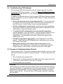
1
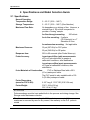
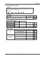
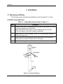
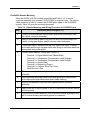
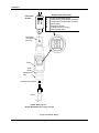
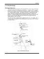
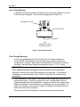
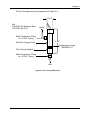
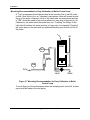
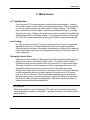
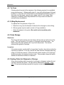
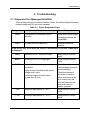
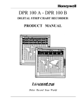
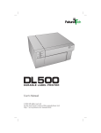
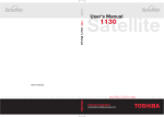
DL5000 Dissolved Oxygen (D.O.) Probe
User’s Manual
70-82-25-114
5/02
Industrial Process Control
Notices and Trademarks
Copyright 2002 by Honeywell
May, 2002
Warranty/Remedy
Honeywell warrants goods of its manufacture as being free of defective materials and faulty
workmanship. Contact your local sales office for warranty information. If warranted goods are
returned to Honeywell during the period of coverage, Honeywell will repair or replace without
charge those items it finds defective. The foregoing is Buyer's sole remedy and is in lieu of all
other warranties, expressed or implied, including those of merchantability and fitness for a
particular purpose. Specifications may change without notice. The information we supply is
believed to be accurate and reliable as of this printing. However, we assume no responsibility for
its use.
While we provide application assistance personally, through our literature and the Honeywell
web site, it is up to the customer to determine the suitability of the product in the application.
Industrial Process Control
Honeywell
1100 Virginia Drive
Fort Washington, PA 19034
DirectLine is a trademark of Honeywell
Other brands or product names are trademarks of their respective owners
ii
DL500 Dissolved Oxygen (D.O.) Probe – User’s Manual
5/02
About This Document
Abstract
This manual provides description, specification, installation, mounting,
maintenance and troubleshooting information for the Honeywell DL5000
Dissolved Oxygen (D.O.) Probe.
Contacts
World Wide Web
The following lists Honeywell’s World Wide Web sites that will be of interest to
our customers.
Honeywell Organization
WWW Address (URL)
Corporate
http://www.honeywell.com
Industrial Process Control
http://www.honeywell.com/ipc
Telephone
Contact us by telephone at the numbers listed below.
United States and
Canada
Organization
Phone Number
Honeywell
1-800-423-9883
Tech. Support
1-888-423-9883
Q&A Faxback
(TACFACS)
1-800-525-7439
Service
Symbol Definitions
The following table lists any symbols used in this document to denote certain
conditions.
Symbol
Definition
Earth Ground. Functional earth connection. NOTE: This connection shall
be bonded to Protective earth at the source of supply in accordance with
national and local electrical code requirements.
5/02
DL5000 Dissolved Oxygen (D.O.) Probe – User’s Manual
iii
Contents
1.
INTRODUCTION ................................................................................................... 1
1.1 Overview ........................................................................................................................1
1.2 Probe Description...........................................................................................................1
1.3 Operating Principal.........................................................................................................1
2.
SPECIFICATIONS AND MODEL SELECTION GUIDE ........................................ 2
2.1 Specifications.................................................................................................................2
2.2 Model Selection Guide ...................................................................................................3
3.
INSTALLATION .................................................................................................... 4
3.1 Mounting and Wiring ......................................................................................................4
DL424/425 Integral Mounting............................................................................................4
DL424/425 Remote Mounting ...........................................................................................5
Series 7020 Remote Mounting and Wiring........................................................................7
Probe System Check ........................................................................................................8
System Check for Probe with Model 7020 ........................................................................8
3.2 Probe Mountings ............................................................................................................9
Wastewater Submersion...................................................................................................9
In-line Flow Mounting......................................................................................................10
Flow Through Mounting ..................................................................................................10
Mounting Recommendation for Easy Calibration in Boiler Control Loop .........................12
4.
MAINTENANCE .................................................................................................. 13
4.1 Introduction ..................................................................................................................13
Inert Fouling: ..................................................................................................................13
Biologically Active Slime: ................................................................................................13
4.2 To Clean ......................................................................................................................14
4.3 O-Ring Replacement....................................................................................................14
4.4 Probe Storage..............................................................................................................14
Short term.......................................................................................................................14
Long term .......................................................................................................................14
4.5 Packing Probe for Shipment or Storage .......................................................................14
5.
TROUBLESHOOTING ........................................................................................ 15
5.1 Diagnostic Error Messages DL424/425 ........................................................................15
5.2 Troubleshooting 7020 Analyzer ....................................................................................17
5.3 Processes Containing Carbon Dioxide .........................................................................17
5.4 Leak Detection in PPB Applications .............................................................................18
iv
DL500 Dissolved Oxygen (D.O.) Probe – User’s Manual
5/02
Tables
Table 3-1 Integral Mounting Procedure ( Figure 3-1)____________________________________ 4
Table 3-2 Remote Mounting and Wiring Procedure for DL5000 Probes____________________ 5
Table 5-1 Online Diagnostic Errors __________________________________________________ 15
Figures
Figure 3-1 Integral Mounting ____________________________________________________ 4
Figure 3-2 Remote Wiring ______________________________________________________ 6
Figure 3-3 Connect/Disconnect Sequence for the Series 7020 D.O. Analyzer ______________ 7
Figure 3-4 Waste Water Mounting ________________________________________________ 9
Figure 3-5 In-Line Mounting Kit _________________________________________________ 10
Figure 3-6 Flow Through Mounting ______________________________________________ 11
Figure 3-7 Mounting Recommendation for Easy Calibration in Boiler Control Loop _________ 12
5/02
DL5000 Dissolved Oxygen (D.O.) Probe – User’s Manual
v
vi
DL500 Dissolved Oxygen (D.O.) Probe – User’s Manual
5/02
Introduction
1. Introduction
1.1 Overview
This document provides description, specification, installation, mounting,
maintenance, and trouble shooting information for the Honeywell DL5000
Dissolved Oxygen (D.O.) probe. This probe can be used with the DL424, DL425,
or the 7020 Series Dissolved Oxygen analyzers.
1.2 Probe Description
The Honeywell probe is housed in either PVC or Stainless steel casing. One end
has a 1” NPT male thread for mounting. The sensor extends from the housing
and is covered by a protective guard (of the same material as the casing) which
allows sample entry while preventing physical damage.
The probe has permanent electrolyte which is sealed at the rear with an
expansion chamber to compensate for pressure changes. The sensor assembly
is permanently potted into the housing and is not field replaceable. Operational
service in wastewater applications should consist of an occasional wash to
remove any large deposits at the sensor end. This can usually be accomplished
without removing the protective guard. If the protective guard is removed,
additional care must be taken to minimize the chance of puncturing a hole in the
probe membrane. See Probe Maintenance section for proper cleaning
procedures.
Physically the probe consists of three electrodes and a thermistor for
temperature measurement and compensation. Two electrodes are interspaced
on a supporting substrate and covered with an electrolyte; these electrodes are
connected as anode and cathode. The third or reference electrode is mounted in
the center of the electrode support and is also in contact with the electrolyte.
The anode and cathode perform the oxygen generation and reduction functions
while the reference electrode maintains the correct electrochemical potential.
1.3 Operating Principal
When the probe is placed into the sample stream, oxygen diffuses through the
membrane and is reduced at the cathode, and an equal amount of oxygen is
generated at the anode. The diffusion continues until the oxygen partial pressure
on both sides of the membrane is equal and a balance exists. The electrical
circuit is designed such that the current necessary to maintain this equilibrium is
converted to read out the dissolved oxygen concentration in the solution.
The reactions are as follows:
At cathode: O2 + 4H+ + 4 e- ® 2H2O
At anode: 2H2O ® O2 + 4H+ + 4 eResult: No net reaction
5/02
DL5000 Dissolved Oxygen (D.O.) Probe – User’s Manual
1
Specifications
2. Specifications and Model Selection Guide
2.1 Specifications
Normal Operating
Temperature Range:
2 – 60 °C (35.6 – 140°F)
Storage Temperature:
2 – 60 °C (35.6 – 140°F) (See Attention)
Maximum Flow Rate:
No dependence on stirring or flow. However, a
minimal flow of 100 ml/min is expected to
provide a “flowing” sample.
for flow through mounting:
300 ml/min
for in-line mounting: 5 gal/min
(18.9 liter/min) in a 1”
Schedule 40 Line
for submersion mounting: Not applicable
Maximum Pressure:
30 psi (207 kPa) for PVC probe
50 psi (345 kPa) for SS probe
Response time:
90% in 60 seconds (after Probe Warm-up)
Probe Accuracy
in parts per billion (ppb) measurements:
±5% or 2 ppb whichever is greater at
calibration conditions, after stabilization
in parts per million (ppm) measurements:
±0.2 ppm at calibration conditions, after
stabilization
Probe Materials of Construction:
PVC or Stainless Steel with a 20 ft.
(6.1m) waterproof cable.
The PVC model is also available with a 100
ft.(30.48m) waterproof cable.
Probe Dimensions
(same for PVC & SS):
Probe Weight:
8 .62” long X 1.315” OD (219 X 34 mm)
PVC 1.24 lb (0.6 kg)
SS: 3.5 lb (1.5 kg)
ATTENTION
Probe membrane must be kept wetted both in the process and during storage. See
Storage under Maintenance section.
The silicone membrane surrounding the D.O. probe is permanent. If this
membrane is removed by user for any reason, the warranty on the D.O. probe is
voided
2
DL500 Dissolved Oxygen (D.O.) Probe – User’s Manual
5/02
Specifications
2.2 Model Selection Guide
Instructions
Select the desired key number. The arrow to the right marks the selection available.
Make one selection from Tables I & II using the column below the proper arrow.
A dot ( ) denotes unrestricted availability.
Key Number
______
-
I
___
II
____
-
KEY NUMBER
DESCRIPTION
DL5000 Dissolved Oxygen Probe - Parts Per Billion
Selection
DL5PPB
DL5000 Dissolved Oxygen Probe - Parts Per Million
DL5PPM
TABLE I - Probe Construction:
Material of Construction
Mounting
PVC
PVC
None
300
400
Remote
PVC
100
200
20'
Remote
316 Stainless Steel
PPB PPM
Cable Length
Integral
316 Stainless Steel
Availability
100'
700
TABLE II - Options
Tagging
None
00_ _
Linen Customer I.D. Tag:
3 lines w/22 characters/line
Stainless Steel Customer I.D. Tag
3 lines w/22 characters/line
LN_ _
Standard Warranty
Extended Warranty
Against Manufacturing
Defects
5/02
1 Year Extended Warranty
2 Years Extended Warranty
SS_ _
_ _00
_ _W2
_ _W3
DL5000 Dissolved Oxygen (D.O.) Probe – User’s Manual
3
Installation
3. Installation
3.1 Mounting and Wiring
The following section describes the installation of the Honeywell D. O. probe.
DL424/425 Integral Mounting
Table 3-1 Integral Mounting Procedure ( Figure 3-1)
Step
Procedure
1
Connect the probe to the process source (using the appropriate mounting
from those supplied for the DL5000).
Make sure that the final position of the installed electronics module
allows the display to be easily viewed by personnel.
2
Apply a thin film of silicon grease on the ID of the electronics module’s
probe mounting cavity.
3
Align the slots on the electronics module with those on the probe and
press down to connect the electronics to the probe.
4
Tighten the locking screw on the bottom rear of the electronics module.
Electronics
Module
Locking Screw in
Rear of Housing
Step 2
Step 3
Step 4
Probe
Step 1
Figure 3-1 Integral Mounting
4
DL500 Dissolved Oxygen (D.O.) Probe – User’s Manual
5/02
Installation
DL424/425 Remote Mounting
When the DL424 or DL425 module is specified with Table II = 6, a remote
connector assembly (part number 51500768-005) is supplied loose. The remote
cable connector is used to connect the DL5000 probe cable to the DL424/425
module. Table 3-2 gives the mounting procedure.
Table 3-2 Remote Mounting and Wiring Procedure for DL5000 Probes
Step
Procedure (Refer to Figure 3-2 )
1
Turning counterclockwise, remove strain relief/cover combination from
the remote connector assembly.
2
Remove the protective plastic bag from the end of the probe cable. Be
careful to keep bare fingers away from coax cable termination.
3
Loosen and remove compression cap from strain relief fitting. Carefully
push cable end through cap and strain relief fitting so that these parts are
strung back along cable jacket.
4
Connect cable leads as follows: See Figure 3-2.
Terminal 1 = Pigtail Shield Lead (Black/White)
Terminal 2 = Temperature Compensation Lead (Orange)
Terminal 3 = Temperature Compensation Lead (Yellow)
Terminal 4 = Anode (Red)
Terminal 5 = Reference (Green)
Terminal 6 = Cathode Silver Pin (Coax)
Earth Ground = Blue
5/02
5
Slide cover along cable and tighten by hand onto the remote connector
assembly.
6
Slide cap along cable and tighten onto cable jacket with small wrench
until cable cannot slide within strain relief rubber bushing.
7
Remove red protective vinyl boot from opposite end of connector
assembly.
8
Apply a thin film of silicon grease to the ID of electronics module’s remote
mounting cavity.
9
Plug remote connector assembly into DL424/425 module aligning polarity
tab of module housing and mating groove on connector.
DL5000 Dissolved Oxygen (D.O.) Probe – User’s Manual
5
Installation
DL5000 Probe Electronics
Electronics
Module
M
O
D
E
1
2
1
2
3
4
5
6
Protective
Vinyl Boot
(remove)
Pigtail Shield (Black/White)
Temperature Compensation (Orange)
Temperature Compensation (Yellow)
Anode (Red)
Reference (Green)
Cathode Silver Pin (Coax)
Earth Ground (Blue)
6
5
4
1
2
3
Cover
Strain
Relief
Compression
Cap
Remote Wiring Cable
Probe
Remote Electronics for
Module DL5000 Dissolved Oxygen Probes
Figure 3-2 Remote Wiring
6
DL500 Dissolved Oxygen (D.O.) Probe – User’s Manual
5/02
Installation
Series 7020 Remote Mounting and Wiring
When connecting the probe to the Series 7020 Analyzer, the probe wiring should
always be kept separated from the AC power wiring. After the analyzer and
probe have been securely mounted, the probe should be connected to the
analyzer.
Before wiring, remove the protective insulator tape from the green lead. To make
wiring easier on the 7020 Series analyzer, loosen the screw at the bottom of
the terminal board and remove the terminal block from the panel while wiring.
Figure 3-3 gives the sequence for connecting and disconnecting the probe from
the 7020 Series analyzer.
CAUTION
When installing the probe the wiring must be done in the order shown in Figure 3-3,
even if the analyzer is not powered. This is because the battery backup card is
continuously supplying a voltage (bias) to the terminals.
Connecting – Shield wire first,
then in this order
Red
Green
Coax
Yellow
Orange
Disconnecting – Go in reverse
Orange - first
Yellow
Coax
Green
Red
Shield Wire
TB5
33
ANODE (Red)
REF (Green)
CATH SILVER PIN (Coax)
THERM+ (Yellow)
THERM – (Orange)
SHIELD (White/Black)
ALL+
ALL –
40
Figure 3-3 Connect/Disconnect Sequence for the Series 7020 D.O. Analyzer
5/02
DL5000 Dissolved Oxygen (D.O.) Probe – User’s Manual
7
Installation
Probe System Check
When the probe is connected for the first time, replaced or just disconnected and
reconnected, a conditioning period of 24 hours is needed before the probe can
make an accurate measurement. During this time period, the probe must be kept
wetted by either putting it in the process water or in a container of water exposed
to air. For ppb applications, it is recommended that process conditions are
used. Once the 24 hour period has elapsed, the probe can be calibrated. The
calibration instructions are as follows:
1. Remove probe from either the process or container of water and put in
ambient air. If probe was in process wastewater, clean probe first per
cleaning instructions under the maintenance section.
If the probe is in a ppb process, expose the probe to air for 2 - 4 hours before
doing an Air calibration.
2. Perform an Air calibration or Sample calibration. Make sure probe
temperature is stable before performing an Air calibration. If temperature is
not stable, the Air calibration will fail.
ATTENTION
Do not perform an Air calibration on a windy day or during freezing temperatures.
The temperature will not stabilize on a windy day and freezing temperatures will
cause the probe’s electrolyte to freeze and the membrane to crack.
3. At completion of a successful air or sample calibration, put probe into process
water.
After the initial calibration, the probe should only be removed from the process
for periodic cleaning and calibration. The recommended cleaning schedule for
ppb applications is monthly and for ppm applications it is bimonthly. If the
probe’s response has slowed or readings are lower than expected prior to the
recommended cleaning schedule, the probe may need to be cleaned more
frequently. The recommended calibration schedule for ppb and ppm
applications is monthly. If individual plant maintenance schedules require it, the
probe may be calibrated more frequently.
System Check for Probe with Model 7020
Perform a system check upon completion of all wiring. AC noise in the various
analyzer output connections may affect the bias amplifier resulting in a DC
current in the reference lead. This DC current will cause dissolution on the silver
reference electrode over time resulting in a shortened probe life.
See Appendix A in the 7020 Operator manual for directions on Noise testing.
8
DL500 Dissolved Oxygen (D.O.) Probe – User’s Manual
5/02
Installation
3.2 Probe Mountings
Wastewater Submersion
Various mounting are available for the Honeywell D.O. probe. Figure 3-4 shows
the probe mounting kit for Wastewater Submersion. Except for the 1” schedule
40 PVC pipe or conduit, this kit contains all pieces needed to mount the probe to
1-1/2” diameter safety railings. The length of the pipe or conduit governs the
depth of the probe immersion while the angle piece governs the horizontal
distance. To minimize debris build-up, place the probe into the process at a 45 °
angle from the horizontal pipe railing. The cable can be routed though the
supporting pipe or tied to its side.
If the kit is not used and plastic pipe is preferred, use 1” to 1 ½” coupling. The
use of the pipe is suggested to avoid whipping of the pipe when used in flowing
or turbulent water.
D.O. Receiver
Pin Fitting (2 req’d)
31063325
(Note location of pins
Wrench 31063326
Clamp on Tee (2 req’d)
31063327
1” Pipe Size
Eye Fitting (2 req’d)
31063329
1 1/2” Pipe Size
24” to 30” Long
1 1/2” Pipe Size
6” to 8” Long
Single Socket Tee
31063328
1” X 1”
Female
Coupling
31063330
D.O. Probe
Assembly
Figure 3-4 Waste Water Mounting
5/02
DL5000 Dissolved Oxygen (D.O.) Probe – User’s Manual
9
Installation
In-line Flow Mounting
In applications where the probe goes directly into the process pipeline, the in-line
flow mounting is available. This mounting is diagramed in Figure 3-5.
30669860-017 O-ring
3/4” NPT (REF)
Customer Installation
Kit #
51452226-001 (SST)
51452226-002 (PVC)
Figure 3-5 In-Line Mounting Kit
Flow Through Mounting
In most low ppb applications, the Pure Water Flow Through mounting is
recommended. This assembly is usually pipe clamp mounted close to the
sampling port. A single 1” pipe clamp is normally all that is needed for physical
mounting. Inlet and outlet fittings are designed to mate to ¼” O.D. tubing.
ATTENTION
When assembling the flow through kit, extreme caution must be used when
installing or removing the probe flow assembly from the probe. The assembly
threads can cut the membrane if they contact it (especially the stainless steel
assemblies).
In ppb applications, the integrity of the sample lines feeding the ppb probe is of
extreme importance. Since the oxygen level in air is usually three orders of
magnitude greater than the sample level, oxygen can leak into the sample lines
without any indication of liquid leaking out, resulting in erroneous readings. To
reduce risk of leaks, use a minimum number of fittings in the sample lines and
make sure each fitting is tightened.
The sample should be discharged to Atmospheric pressure (open drain).
10
DL500 Dissolved Oxygen (D.O.) Probe – User’s Manual
5/02
Installation
The flow through mounting is diagramed in Figure 3-6.
1 5/16”
Kits
51452187-001 Stainless Steel
51452187-002 PVC
Outlet
Male Compression Fitting
for 1/4 O.D. Tubing
9 1/2”
Dissolved Oxygen Probe
Replacement O-ring
30669860-017
Flow Through Adapter
Male Compression Fitting
for 1/4 O.D. Tubing
Inlet
Figure 3-6 Flow Through Mounting
5/02
DL5000 Dissolved Oxygen (D.O.) Probe – User’s Manual
11
Installation
Mounting Recommendation for Easy Calibration in Boiler Control Loop
A "Trap" arrangement should be plumbed in the incoming flow to the DO probe
so that if flow is shut off or an "Upstream" pipe opened, water will remain around
the tip of the probe. Keeping it moist on the outlet side, an arrangement such as
a "TEE" should be made to assure that when the 3-way valve is opened (for Air
Calibration), the water within the probe flows out. "Cracking" the fittings on the
inlet side will achieve the same result as a 3-way valve, but repeated "Cracking"
will cause wear on the parts and any additional handling may shorten the life of
the probe.
AIR
PROBE
PRESS
FLOW
METER
TEMP
FLOW
X
DRAIN
TRAP
3-WAY
VALVE
DRAIN
Figure 3-7 Mounting Recommendation for Easy Calibration in Boiler
Control Loop
To avoid drying out the probe sensor when the sampling point is shut off, a water
trap should be made in the inlet piping
12
DL500 Dissolved Oxygen (D.O.) Probe – User’s Manual
5/02
Maintenance
4. Maintenance
4.1 Introduction
The Honeywell D. O. probe requires no internal probe maintenance. However,
like all other probes, it does need to be cleaned periodically. After a long period
of use, the oxygen transfer may cease due to a coating buildup. This buildup
may consume or block the oxygen, increase the response time and / or reduce
the probe accuracy. Cleaning the probe is easy and is normally accomplished by
agitating the probe in a container of fluid. The cleaning fluid can vary from water
to a 10% HCl solution depending on the type of buildup or fouling encountered.
Inert Fouling:
(ex. hair, grease, and solids) This type of fouling normally occurs in wastewater
applications; however, rust-like contaminants may occur in ppb applications.
When a significant amount of this debris is deposited on the probe, the response
time of the probe slows down. Normal cleaning practices should restore probe to
correct operation.
Biologically Active Slime:
This type of fouling consists of biologically active slime adhering either loosely or
tightly to the probe or the protective cap or both. This slime can be visible or
invisible and may produce a sticky feel to the probe and / or cap’s surface area.
This type of fouling is usually characterized by the following performance: the
signal drifts slowly downward for several hours (or days) and then drops
precipitously toward zero in a matter of a few hours or less. Proper air calibration
can be restored only after very careful wiping of the probe tip or a 30 second
rinse in a 10% HCl solution. The time between cleanings can be extended by
relocating the probe to a cleaner environment (nearer the effluent) or relocating
the probe to where the water is flowing faster. After these actions are taken, a
cleaning schedule should be established.
ATTENTION
Never use a brush to clean a Honeywell D.O. probe as it can cause a tear in the
probe membrane rendering it inoperable. This type of abuse is not covered under
probe warranty.
5/02
DL5000 Dissolved Oxygen (D.O.) Probe – User’s Manual
13
Maintenance
4.2 To Clean
Cleaning should consist of the simplest of the following required to re-establish
proper performance: 1.)Rinsing with water 2.) rinse with mild detergent followed
by water 3.) rinse with 10% HCl followed by mild detergent followed by water. If
the probe must be wiped, carefully use a paper towel or cotton swab. After
cleaning is completed, place the probe back into the process and allow 60
minutes before a calibration.
4.3 O-Ring Replacement
To replace the O-ring shown in Figure 3-6:
1. Place the o-ring over the threads of either the flow through or in-line fitting.
2. Silicone grease may be used to assist in O-ring installation.
3.
Attach the adapter to the probe. Be careful not to touch the probe
membrane.
4.4 Probe Storage
Short term
The Honeywell probe arrives from the factory with an red cap on the end of the
probe. This cap contains a 3% solution of Isopropyl alcohol and water. The
water keeps the probe wetted until it is put into the process. The alcohol
minimizes the growth of bacteria.
Long term
If the probe remains on the shelf for longer than 6 months, the solution inside the
cap must be replaced. To do this, remove the side mounted, threaded pipe plug
using a 3/16 hex key wrench. Fill the hole with a fresh solution of 3% Isopropyl
alcohol and water, and replace the hex screw. This procedure keeps the probe
wetted and minimizes incidence of bacteria.
4.5 Packing Probe for Shipment or Storage
When removing the probe from service for storage or shipment, replace the red
cap that came with the probe. Fill the probe as described in Storage – Long
term. This prevents damage caused by long-term contact with the other probe
leads.
14
DL500 Dissolved Oxygen (D.O.) Probe – User’s Manual
5/02
Troubleshooting
5. Troubleshooting
5.1 Diagnostic Error Messages DL424/425
When a diagnostic error or status condition occurs, the Online Display alternates
between measured DO and a text message.
Table 5-1 Online Diagnostic Errors
What you see
CnFG
FALt
What it is
What to do
Configuration or Calibration data is
defective.
Reset unit or cycle power.
Unit electronics are defective.
Replace electronics
module.
Second occurrence will
show FALt.
These errors may occur when on-line DO Concentration or on-line Temperature
is displayed.
dOHI
Measured DO is > 20 ppm/200 ppb
Bring process to within
limits
dOLo
Measured DO is < 0.00 ppm/ppb
Bring process to within
limits
PrbE
Probe is defective, wrong type, or not
connected.
Check for an electrical
short between the anode
and the cathode.
Probe current is excessive with probe
voltage near 0 volts.
Forces the output to burnout level
(greater than 22 mA).
5/02
Check the reference
electrode connection.
When the source of the
error is removed, the
error will clear and the
output will return to
normal operation.
T HI
Measured temperature is > 60 °C
Bring process to within
limits
T LO
Measured temperature is < 2.0 °C
Bring process to within
limits
DL5000 Dissolved Oxygen (D.O.) Probe – User’s Manual
15
Troubleshooting
What you see
bErr
What it is
Probe Bias Error:
Probe current has exceeded expected
probe current by 33% for at least 20
seconds.
If the excessive current condition
continues after a manual probe bias ,
the PrbE error is generated. If excessive
current is not present then the bErr
remains.
Application related shift in probe bias
voltage
What to do
Remove the probe from
process and do a probe
bias calibration. In ppm
applications in processes
containing CO2, the probe
may be left in the process
and the Bias can be
manually adjusted.
Remove the probe from
the process and do an Air
Calibration
These errors may occur during Air, Sample and Probe Bias calibration and
abort the calibration process.
FAIL
These error messages are preceded by
the message “FAIL”
Press Mode to return to
online display.
ArnG Air Calibration failed due to a
measured probe current not in the
acceptable range
Stbl
Air Calibration failed due to input
measurement instability
bErr Bias voltage calibration failed due
to unacceptable input current.
Replace Probe.
16
DL500 Dissolved Oxygen (D.O.) Probe – User’s Manual
5/02
Troubleshooting
5.2 Troubleshooting 7020 Analyzer
The Honeywell 7020 Series Operator manual contains many tips for trouble
shooting the 7020 Series analyzer. Consult the Matrix of Potential Problems
and Solutions under Section 5.2 in the Operator manual for information on your
particular problem.
In addition, the appendix section of the Honeywell 7020 Series Operator manual
provides information on various subjects related to the D.O. probe, including the
following topics:
· Excess AC noise can result in a shorten probe life. To ensure that there
is no excess noise on the probe leads, use the procedure in Appendix A in
the 7020 manual – Noise Testing to test your probe installation.
· If a D.O. reading doesn’t seem correct, check that the probe and analyzer
are working correctly by using the procedures provided in Appendix B in the
7020 manual – Probe and Analyzer Tests.
· To confirm the D.O. measurement in air at a specific temperature,
consult Appendix E in the 7020 manual – Percent Saturation Readout to get
the expected DO concentration in air or air saturated water at various
temperatures. This information will confirm if the probe is giving a valid
measurement in air.
· If a leak is suspected in a ppb system, consult Appendix F in the 7020
manual – Leak Detection in PPB Applications to understand how to use the
D.O. probe to find a leak.
· Want proof that a D.O. probe can go down to zero ppbs? Consult
Appendix G in the 7020 manual – Procedure for Low level ppb Dissolved
Oxygen testing to confirm that your probe can get down to zero ppbs.
5.3 Processes Containing Carbon Dioxide
When measuring D.O. in a process containing carbon dioxide (e.g. beer or soda)
special procedures are required to protect the probe. To remove the probe from
the line:
1. Shut off sample line containing CO2.
2. Purge the line containing the probe with fresh water at the same pressure for
15 minutes to remove the CO2 from the D. O. probe.
3. Remove probe when convenient.
CAUTION
Not following this procedure will cause internal rupture of the membrane rendering
the probe inoperable, un-repairable and void of any probe warranty. For optimum
performance in this application, the bias voltage should be adjusted to measure
450 mV instead 600 mV. Review the Series 7020 operator manuals for adjusting
the Probe Bias.
5/02
DL5000 Dissolved Oxygen (D.O.) Probe – User’s Manual
17
Troubleshooting
5.4 Leak Detection in PPB Applications
Before performing and air leak detection, it is necessary to determine that both
the probe and analyzer are working properly.
First, check to see that the probe contains an O-ring. Per the probe directions, an
O-ring must go into a probe that is used in ppb applications. This creates a tight
seal between the probe and flow chamber.
MAKE SURE THIS O-RING IS IN THE PROBE.
1. Unless already in air, open the probe to air for 30 seconds.
2. Put it back into the process again.
3. Allow the DO to drift down to the 20-30 ppb range. The 20-30 ppb range was
chosen because the reading was low enough that the drift was small with
respect to the changes observed for various flow rates but high enough that
changes could be observed.
4. At this range, vary the flow rate from 10 to 100 ml/min. These low flow rates
were selected for two reasons. The first, the tester many only have a 0 - 100
ml/min flow indicator. The other reason, is a leak that exists at this low flow,
will cause a change in the DO reading.
5. If the DO value at 10 ml/min exceeds the DO value at 100 ml/min, a leak is
present in the sampling line.
6. Fixing the leak may require plastic tubing to be replaced with metal tubing,
tape to be put on fittings, and/or fittings at the bottom of the probe to be
tighten securely.
7. Now, repeat Steps 2 - 6 until the flow can be changed from >100 ml/min to 10
ml/min with no change in the DO value.
18
DL500 Dissolved Oxygen (D.O.) Probe – User’s Manual
5/02
Troubleshooting
5/02
DL5000 Dissolved Oxygen (D.O.) Probe – User’s Manual
19
Sales and Service
For application assistance, current specifications, pricing, or name of the nearest Authorized Distributor,
contact one of the offices below.
ARGENTINA
HONEYWELL S.A.I.C.
BELGRANO 1156
BUENOS AIRES
ARGENTINA
Tel. : 54 1 383 9290
ASIA PACIFIC
HONEYWELL ASIA
PACIFIC Inc.
Room 3213-3225
Sun Kung Kai Centre
N° 30 Harbour Road
WANCHAI
HONG KONG
Tel. : 852 829 82 98
AUSTRALIA
HONEYWELL LIMITED
5 Thomas Holt Drive
North Ryde Sydney
NSW AUSTRALIA 2113
Tel. : 61 2 353 7000
AUSTRIA
HONEYWELL AUSTRIA
G.m.b.H.
Handelskai 388
A1020 VIENNA
AUSTRIA
Tel. : 43 1 727 800
BELGIUM
HONEYWELL S.A.
3 Avenue de Bourget
B-1140 BRUSSELS
BELGIUM
Tel. : 32 2 728 27 11
BRAZIL
HONEYWELL DO
BRAZIL
AND CIA
Rua Jose Alves Da
Chunha
Lima 172
BUTANTA
05360.050 SAO PAULO
SP
BRAZIL
Tel. : 55 11 819 3755
BULGARIA
HONEYWELL EOOD
14, Iskarsko Chausse
POB 79
BG- 1592 Sofia
BULGARIA
Tel : 359-791512/
794027/ 792198
CANADA
HONEYWELL LIMITED
THE HONEYWELL
CENTRE
300 Yorkland Blvd.
NORTH YORK, ONTARIO
M2J 1S1
CANADA
Tel.: 800 461 0013
Fax:: 416 502 5001
CZECH
REPUBLIC
HONEYWELL, Spol.s.r.o.
Budejovicka 1
140 21 Prague 4
Czech Republic
Tel. : 42 2 6112 3434
DENMARK
HONEYWELL A/S
Automatikvej 1
DK 2860 Soeborg
DENMARK
Tel. : 45 39 55 56 58
FINLAND
HONEYWELL OY
Ruukintie 8
FIN-02320 ESPOO 32
FINLAND
Tel. : 358 0 3480101
FRANCE
HONEYWELL S.A.
Bâtiment « le Mercury »
Parc Technologique de St
Aubin
Route de l’Orme
(CD 128)
91190 SAINT-AUBIN
FRANCE
Tel. from France:
01 60 19 80 00
From other countries:
33 1 60 19 80 00
GERMANY
HONEYWELL AG
Kaiserleistrasse 39
D-63067 OFFENBACH
GERMANY
Tel. : 49 69 80 64444
HUNGARY
HONEYWELL Kft
Gogol u 13
H-1133 BUDAPEST
HUNGARY
Tel. : 36 1 451 43 00
ICELAND
HONEYWELL
Hataekni .hf
Armuli 26
PO Box 8336
128 reykjavik
Iceland
Tel : 354 588 5000
ITALY
HONEYWELL S.p.A.
Via P. Gobetti, 2/b
20063 Cernusco Sul
Naviglio
ITALY
Tel. : 39 02 92146 1
MEXICO
HONEYWELL S.A. DE
CV
AV. CONSTITUYENTES
900
COL. LOMAS ALTAS
11950 MEXICO CITY
MEXICO
Tel : 52 5 259 1966
THE NETHERLANDS
HONEYWELL BV
Laaderhoogtweg 18
1101 EA AMSTERDAM
ZO
THE NETHERLANDS
Tel : 31 20 56 56 911
NORWAY
HONEYWELL A/S
Askerveien 61
PO Box 263
N-1371 ASKER
NORWAY
Tel. : 47 66 76 20 00
POLAND
HONEYWELL Sp.z.o.o
UI Domainewksa 41
02-672 WARSAW
POLAND
Tel. : 48 22 606 09 00
PORTUGAL
HONEYWELL
PORTUGAL LDA
Edificio Suecia II
Av. do Forte nr 3 - Piso 3
2795 CARNAXIDE
PORTUGAL
Tel. : 351 1 424 50 00
REPUBLIC OF IRELAND
HONEYWELL
Unit 1
Robinhood Business
Park
Robinhood Road
DUBLIN 22
Republic of Ireland
Tel. : 353 1 4565944
REPUBLIC OF
SINGAPORE
HONEYWELL PTE LTD
BLOCK 750E CHAI
CHEE ROAD
06-01 CHAI CHEE IND.
PARK
1646 SINGAPORE
REP. OF SINGAPORE
Tel. : 65 2490 100
REPUBLIC OF SOUTH
AFRICA
HONEYWELL
Southern Africa
PO BOX 138
Milnerton 7435
REPUBLIC OF SOUTH
AFRICA
Tel. : 27 11 805 12 01
ROMANIA
HONEYWELL Office
Bucharest
147 Aurel Vlaicu Str.,
Sc.Z.,
Apt 61/62
R-72921 Bucharest
ROMANIA
Tel : 40-1 211 00 76/
211 79
RUSSIA
HONEYWELL INC
4 th Floor Administrative
Builiding of AO "Luzhniki"
Management
24 Luzhniki
119048 Moscow
RUSSIA
Tel : 7 095 796 98 00/01
SLOVAKIA
HONEYWELL Ltd
Mlynske nivy 73
PO Box 75
820 07 BRATISLAVA 27
SLOVAKIA
Tel. : 421 7 52 47 400/
425
SPAIN
HONEYWELL S.A
Factory
Josefa Valcarcel, 24
28027 MADRID
SPAIN
Tel. : 34 91 31 3 61 00
SWEDEN
HONEYWELL A.B.
S-127 86 Skarholmen
STOCKHOLM
SWEDEN
Tel. : 46 8 775 55 00
SWITZERLAND
HONEYWELL A.G.
Hertistrasse 2
8304 WALLISELLEN
SWITZERLAND
Tel. : 41 1 831 02 71
TURKEY
HONEYWELL
Otomasyon ve Kontrol
Sistemlen San ve Tic
A.S.
(Honeywell Turkey A.S.)
Emirhan Cad No 144
Barbaros Plaza C. Blok
Kat 18
Dikilitas 80700 Istanbul
TURKEY
Tel : 90-212 258 18 30
UNITED KINGDOM
HONEYWELL
Unit 1,2 &4 Zodiac House
Calleva Park
Aldermaston
Berkshire RG7 8HW
UNITED KINGDOM
Tel : 44 118 906 2600
U.S.A.
HONEYWELL INC.
INDUSTRIAL PROCESS
CONTROLS
1100 VIRGINIA DRIVE
PA 19034-3260
FT. WASHINGTON
U.S.A.
Tel. : 1-800-343-0228
VENEZUELA
HONEYWELL CA
APARTADO 61314
1060 CARACAS
VENEZUELA
Tel. : 58 2 239 0211
Industrial Process Control
Honeywell
1100 Virginia Drive
Fort Washington, PA 19034
70-82-25-114 0502 Printed in USA
www.honeywell.com/ipc