1
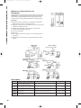
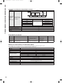
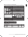
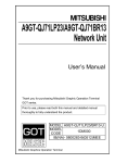
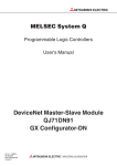
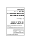
C1-Q Series 2009-2
3/27/09
5:22 PM
Page 53
Overview of Networks
Enterprise Level
When choosing a network solution a number of criteria may come into play.
Topology, bus speed, communications distance, redundancy, data transfer
capabilities, the number of nodes the network can support, deterministic
capabilities, cost, ease-of-use, third party support to name just a few.
Control Level
PC - Controller
PC - Controller
Controller - Controller
Controller - Device
(HMI, I/O, VFD, Servo, etc.)
Device Level
But most importantly, will it work well within your specific application? When
developing our family of network products, we’ve taken all these factors
into consideration — assuring users, all the necessary features and capabilities
are packaged into the network product they have selected.
Sensors,
Valves,
etc.
Sensor
Level
From top to bottom in the network hierarchy, from open architecture protocols
to seamless engineered systems, from sensor to enterprise level, we offer a
host of powerful network solutions for users to choose from. The one common
denominator with all Mitsubishi Electric network products is unmatched performance. In relative performance data comparisons, all our network solutions meet,
exceed or dramatically outperform most competitive networks available on the
global market today.
While bus speed is a critical factor in measuring performance, there are
several other reasons why Mitsubishi Electric network solutions excel
over others. Easy connectivity, seamless integration, synergistic performance characteristics of a Mitsubishi Electric controlled network and above
all else — maximum levels of uptime without sacrificing performance or
productivity. Whether you have an entire factory floor or just an individual
machine to network, you’ll find Mitsubishi Electric’s expansive range of
network options to be the superior choice.
Enterprise Level
Specifications
Ethernet (100base-TX)
Ethernet (10base-T)
Ethernet (10base-5)
Ethernet (10base-2)
Network Level
Enterprise
Enterprise
Enterprise
Enterprise
Star (via hub)
Star (via hub)
Bus
Bus
Cat. 5 (UTP/STP)
Cat. 5 (UTP/STP)
via AUI transceiver
Coax
Transmission Speed
100Mbit/s
10Mbit/s
10Mbit/s
10Mbit/s
Number of Stations
Two levels of cascade
connections via hubs
Four levels of cascade
connections via hubs
100/segment
30/segment
185/segment
Architecture
Communications Media
Maximum Distance (m)
100/segment
100/segment
500/segment
Master Module
N/A
N/A
N/A
N/A
Remote I/O
N/A
N/A
N/A
N/A
Control Level
Specifications
Network Level
Architecture
Communications Media
Transmission Speed
Number of Stations
Maximum Distance (m)
Master Module
Remote I/O
CC-Link IE
Control
Loop
Fiber
1000Mbit/s
120
66,000
Yes (and local)
No
MELSECNET/H
Control
Bus/Loop
Fiber/Coax
10/25Mbit/s (depends on module used)
64 (fiber)/32 (coax)
30,000 (fiber)/500 (coax)
Yes (and local)
Yes
Note: MELSECNET/H is backwards compatible with MELSECNET/10. CC-Link IE was formerly known as MELSECNET/G.
Device Level
Specifications
CC-Link
DeviceNet
PROFIBUS-DP
MODBUS/TCP
MODBUS/RTU
Network Level
Device
Device
Device
Device
Device
Architecture
Bus
Bus
Bus
Star (via hub)
Bus
Communications Media
STP
Thick/thin trunkline
Cat. 5 (UTP/STP)
STP
Transmission Speed
10Mbit/s (all devices)
0.5Mbit/s
100Mbit/s
115kbps
Number of Stations
64
64
STP
12Mbit/s (depends
on devices used)
60
64
64
1200/segment (extend up to
13.2km with repeaters)
500
1200
100
1200
Yes (and local)
Yes (and slave)
Yes
Yes (and slave)
Yes (and slave)
Yes
Yes
Yes
Yes
Yes
Maximum Distance (m)
Master Module
Remote I/O
Sensor Level
Specifications
CC-Link/LT
AS-i
Network Level
Sensor
Sensor
Architecture
Bus
Star, bus or tree
Communications Media
Dedicated mechanically keyed cable
Transmission Speed
2.5Mbt/s
Number of Stations
64
172kbit/s
31
Maximum Distance (m)
700
100
Master Module
Yes
Yes
Remote I/O
Yes
Yes
Mitsubishi Electric Automation
|
Programmable Automation Controller / PAC 53
n PROGRAMMABLE AUTOMATION CONTROLLER / PAC
C1-Q Series 2009-2
3/27/09
5:22 PM
Page 54
MELSEC Q Series / iQ Ethernet Enterprise Level
Network Modules
Typically Ethernet is used to link shop-floor systems to higher level IT systems for
SCADA (Supervisory Control And Data Acquisition) monitoring, maintenance, and
similar functions. The Q Series Ethernet modules provide a method of linking
automation systems to existing standard LAN infrastructures throughout a plant.
Key Features:
n
n
n
n
n
n
n
GX-Developer provides complete support for configuration and maintenance
of Ethernet links (no need for accessory plug-in modules)
Programming, monitoring, email & FTP capabilities for remote system monitoring
& maintenance via Ethernet connection
Compatible with existing LANs via range of physical connection formats
(10base-T, 100base-TX, 10base-5, 10base-2)
Peer-to-peer communication
Multiple ports
Acts as a gateway into lower level networks for access to individual stations on
large networks
“Keep Alive” function allows the status of external equipment to be monitored
via TCP/IP
Required Manuals
Model Number
Description
Contents
IB(NA)0800009
Ethernet Interface Module User’s Manual (Hardware)
Basic information on QJ71E71-100, QJ71E71 & QJ71E71-B2
QJ71E71-100, QJ71E71, QJ71E71-B2
Yes
–
SH(NA)080009
Q Corresponding Ethernet Interface Module User’s
Manual (Basic)
Covers programming and using the Ethernet modules
No (purchase separately)
–
SH(NA)080010
Q Corresponding Ethernet Interface Module User’s
Manual (Application)
Covers higher level functions, such as email, FTP, and integration with
No (purchase separately)
other networks
–
SH(NA)080008
Q Corresponding MELSEC Communication Protocol
Reference Manual
Reference guide to the MC Protocol used by the Q Series Ethernet
modules (Also used by the QJ71C24 & QJ71C24-R2 )
No (purchase separately)
–
SH(NA)080180
Manual (Web Function) Q Corresponding Ethernet
Interface Module User’s
Guide to using the Ethernet modules with an Internet connection
No (purchase separately)
–
Note: Many of these manuals are available by free download from our website, www.meau.com
54
Included?
Stocked Item
C1-Q Series 2009-2
3/27/09
5:22 PM
Page 55
Ethernet Enterprise Level Network Modules
QJ71E71-100
Model Number
100BASE-TX
10BASE-T
QJ71E71-B5
QJ71E71-B2
10BASE5
10BASE2
Stocked Item
S
–
–
Certification
UL • cUL • CE
UL • cUL • CE
UL • cUL • CE
Data Transmission Speed
Communication Mode
100Mbps
10Mbps
Full-duplex/Half-duplex
Half-duplex
Transmission Method
Transmission
Specifications
Base band
Maximum Node-to-Node Distance
Maximum Segment Length
—
2500 m (8202.10 ft.)
925 m (3034.77 ft.)
100 m (328.08 ft.) (*1)
500 m (1640.42 ft.)
185 m (606.96 ft.)
100 units/ segment
30 units/ segment
2.5 m (8.20 ft.)
0.5 m (1.64 ft.)
Cascade connection
Maximum 2 stages
Maximum Number of Modes/Connection
Interval Between the Minimum Nodes
Cascade connection
Maximum 4 stages
—
No. of Simultaneously Open Connections Allowed
16 connections (Connections usable by the sequence program)
Fixed Buffer
Transmission Data
Storage Memory
1 k words x 16
Random Access Buffer
E-mail
6 k words x 1
Attached File
6 k words x 1
Main Text
960 words x 1
Number of Occupied I/O Points
32 points/1 slot (I/O assignments: intelligent)
5VDC Internal Current Consumption
12VDC External Power Supply Capacity (Transceiver)
0.50A
0.50A
0.60A (*3)
—
(*2)
—
External Dimensions (H x W x D) mm (in)
98 x 27.4 x 90 (3.86 x 1.08 x 3.54)
Weight kg (lb)
0.11 (0.24)
0.12 (0.26)
0.13 (0.29) (*3)
Notes:
1. Length between the Hub and node.
2. It is necessary to apply a transceiver, or a device that meets AUI cable specifications.
3. The product with first 5 digits of serial number “05049” or earlier is different as follows:
• 5VDC internal current consumption: 0.70A
• Weight: 0.14kg (0.31lb.)
Email Specifications
Data Size
Attached File
6k words x 1
Main Text
960 words x 1
Data Transfer Method
Subject
When Sending : Either an attached file or text is sent. (Selectable)
When Receiving: Attached file is received.
US-ASCII format or ISO-2022-JP (Base 64)
Attached File Format
MIME format
MIME
Data Format of Attached File
Division of Attached File
Send (Encode)
Receive (Decode)
Version 1.0
Binary, ASCII or CSV can be selected.
File name: XXXX.bin (binary), XXXX.asc (ASCII), XXXX.csv (CSV) (CSV: Comma Separated Value)
Cannot be divided (only one file can be sent/received)
*When divided files are received, the first file portion is received and the others are discarded.
Subject: Base 64/7bits • Main Text: 7 bits
Encryption
No
Compression
Communications with the Mail Server
Attached file: Base 64
Subject : (Not decoded)
Text : (Unreceivable)
Attached file encoding: Base 64/7 bits/8 bits/Quoted Printable
No
SMTP (sending server) port number = 25
POP3 (receiving server) port number = 110
Mitsubishi Electric Automation
|
Programmable Automation Controller / PAC 55
n PROGRAMMABLE AUTOMATION CONTROLLER / PAC
C1-Q Series 2009-2
3/27/09
5:22 PM
Page 56
MELSEC Q Series / iQ CC-Link IE Control Level Master/Local Network Modules
n Variety of Reliability, Availability & Serviceability (RAS) functions to
CC-Link IE is an industry leading alternative for open control level
networking. Originally introduced as MELSECNET/G, it introduces
an unprecedented 1Gbit/s Ethernet physical layer fiber topology for
system performance surpassing any other network technology.
MELSECNET/G has been turned over to the open administration
of the CC-Link Partner Association (CLPA), and is now known as
CC-Link IE. Mitsubishi offers full support for CC-Link IE via the
Q Series Automation Platform and the iQ Platform system.
n
n
n
n
Key features:
n
n Practically unlimited bandwidth (1Gbit/s)
n Noise immune, fault tolerant dual loop optical fiber media
allow network operation to continue despite broken media, power
failures, etc
Extensive diagnostic functions and tools to monitor
network operation and quickly troubleshoot faults
Up to 120 stations per network
Up 550 meters between stations
Connect up to 239 networks
Program free parameter based configuration for
cyclic communications
n Uses industry standard 1000base-SX optical fiber
and LC type connectors
Required Manuals
Model Number
Description
Contents
Included?
IB(NA)0800364E
CC-Link IE Network Module User’s Manual (Hardware)
Basic information on QJ71GP21-SX & QJ71GP21S-SX
Yes
–
SH(NA)080668ENG
CC-Link IE Network System Reference Manual
(Controller Network)
Reference guide to the CC-Link IE network technology
No (purchase
separately)
–
Note: Many of these manuals are available by free download from our website, www.meau.com.
CC-Link IE Optical Fiber Cordsets
Model Number
Description
n M-B-LL
QG-n
CC-Link IE cordset, where n represents length 1, 2, 3, 5, 10, 15, 20, 25, 30, 35, 40 or 50 meters
Model Number
Stocked Item
S
QJ71GP21-SX
Stocked Item
QJ71GP21S-SX
S
–
Certification
UL • cUL • CE
LB
LW
LX
LY
LB
Max. Link Points LW
Per Station
LX
LY
Transient Transmission Capacity
Communication Speed
32K points (32768 points, 4KB)
128K points (131072 points, 256KB)
8K points (8192 points, 1KB)
8K points (8192 points, 1KB)
16K points (16384 points, 2KB)
16K points (16384 points, 32KB)
8K points (8192 points, 1KB)
8K points (8192 points, 1KB)
Up to 1920 bytes
1Gbps
Number Of Stations Per Network
When Universal model QCPU is used for control station: 120; (Control station: 1, Normal station: 119)
When High Performance model QCPU is used for control station: 64
(Control station: 1, Normal station: 63)
Max. Link Points
Per Network
Connection Cable
Optical fiber cable (Multi-mode fiber)
Overall Cable Distance
Station-To-Station Distance (Max.)
Max. Number Of Networks
Max. Number Of Groups
Number Of Occupied I/O Points
External Power
Supply
Voltage
Current
Terminal Screw Size
Applicable Solderless
Terminal
Applicable Wire Size
Tightening Torque
Allowable Momentary Power
Failure Time
66000m (When 120 stations are connected)
550m (Core/Clad = 50/125 (µm))
239
32
48 (I/O assignment: Empty first half: 16 points,
32 (Intelli.: 32 points)
Latter half: 32 points for intelli.)
20.4V to 31.2VDC
0.28A
M3
R1.25-3
No external power supply function
0.3 to 1.25mm2
0.42 to 0.58N•m
1ms (Level PS1)
Noise Immunity
Internal Current Consumption (5VDC)
Dimensions (H x W x D) mm
Weight (kg)
56
Stocked Item
0.85A
98 x 27.4 x 90
0.18
By noise simulator of 500Vp-p noise voltage, 1µs noise width,
and 25 to 60Hz noise frequency
0.90A
98 x 55.2 x 90
0.28
C1-Q Series 2009-2
3/27/09
5:22 PM
Page 57
MELSEC Q Series / iQ MELSECNET/H Control Level
Master/Local Network Modules
Use MELSECNET/H to link Q Series systems together on a control level network for the
coordinated operation of multiple controllers on a production line or large machine. MELSECNET/H
also supports the direct connection of PCs onto the network for SCADA or maintenance applications.
MELSECNET/H was designed to offer similar performance benefits to most industrial Ethernet
systems, while offering the high degree of performance required in an automation environment.
Key Features:
n
n
n
n
n
n
n
n
n
n
n
n
n
n
n
n
MELSECNET/H configuration and maintenance is supported by GX Developer with no need for
accessory plug-ins
High-speed communications at up to 25Mbit/s (depending on modules used)
Backwards compatible with existing MELSECNET/10 installations.
Guaranteed determinism via token passing scheme
Scalable to exceed the needs of the largest installations (over 15,000 stations in one system)
Up to 30km loop circumference via fiber connections
Loop topology optical fiber media offers maximum speed and dual redundancy
Single bus coax offers many performance benefits with economical media
No programming required to establish cyclic network communications; just set parameters
in GX-Developer
Transient communications permit asynchronous peer to peer messaging
Loop topology offers recovery from media breaks via automatic loop back
Floating master maintains network operation by allowing any station to take over after the original
master goes offline
Offline stations return to the network automatically when able to
Extensive diagnostic functions to monitor network operation and status
Program & monitor across the network
Transmit up to 35 kbytes of uninterrupted data for increased performance and simpler
programming (S/N 06092x, Version D units or later)
Required Manuals
Model Number
Description
Contents
Included?
IB(NA)0800144
MELSECNET/H Network Module User’s Manual
(Hardware) QJ71LP21-25, QJ71LP21G, QJ71BR11
Basic information on QJ71LP21-25, QJ71LP21G &
QJ71BR11 (MELSECNET/H master modules)
Yes
SH(NA)080049
MELSECNET/10H for Q Network System Reference
Manual (PLC to PLC network)
General reference to MELSECNET/H (MELSECNET/H & MELSECNET/10H are equivalent terms)
No (purchase separately)
Stocked Item
–
–
Note: Many of these manuals are available by free download from our website, www.meau.com
MELSECNET/H Optical Fiber
Optical fiber media cable is available for connecting MELSECNET/H networks.
Model Number
Description
AS-1000M-B
Optical fiber cable, sold by the meter
Stocked Item
S
DL-72ME
AS-1000M-B connector, MEAU offers the service to provide pre-terminated cables as required
S
PA7003
Splice connector for joining pre-terminated AS-1000M-B cable
–
CAK-0068ME
Optional termination tool kit for AS-1000M-B and DL-72ME for on-site termination work
–
Mitsubishi Electric Automation
|
Programmable Automation Controller / PAC 57
n PROGRAMMABLE AUTOMATION CONTROLLER / PAC
C1-Q Series 2009-2
3/27/09
5:22 PM
Page 58
MELSECNET/H Control Level Master/Local Network Modules
QJ71LP21-25
Model Number
Stocked Item
Certification
Connection Form
QJ71LP21S-25
QJ71LP21G
–
–
UL • cUL • CE
UL • cUL • CE
Duplex loop type
S
UL • cUL • CE
Max. Number of Link Points Per Network
QJ71LP21GE
–
UL • cUL • CE
QJ71BR11
S
UL • cUL • CE
Simplex bus type
LX/LY
LB
MELSECNET/H mode
8192 points (8k bits)
16384 points (16k bits)
MELSECNET/10 mode
8192 points (8k bits)
8192 points (8k bits)
W
16384 points (16k words)
8192 points (8k words)
Max. Number of Link Points Per Station
Transient Transmission Capacity
Transmission Speed
Communication System
Synchronization
Modulation System
Transmission Code
[LW+LB+LY<=2000 bytes (cyclic communication)]+[LW+LB+LY<=2000 bytes (low-speed cyclic communication)]
Max. 1920 bytes/frame
10Mbps/25Mbps (depending on switch setting) (*1)
10Mbps
10Mbps
10Mbps
Token passing
Flag synchronization (frame synchronization system)
Base band system
NRZI (Non Return to Zero Inverted)
Cable Type
Optical (AS-1000M-B
(SI, 200/250)) (*2)
Optical (AS-1000M-B
(SI, 200/250)) (*2)
Transmission Frame Format
Error Control System
Max. Number of Networks
Max. Number of Groups
Optical (GI-50/125)
Optical (GI-62.5/125)
Coaxial 75Ω
RG-59B/U RG-11A/U
HDLC conformance (frame format)
CRC (X 16+X 12+X 5+1) and time-out retry
239
32
Number of Stations Connected
64 stations (1: control station, 63: normal station)
32 stations
(1: control station,
31: normal station)
30km (98360.67 ft.)
500m (1639.34 ft.)
RG-11A/U) / 300m (983.61
ft.) (RG-59B/U)
Overall Distance
Transmission Speed
Cable Type
10Mbps
Station to Station Distance
25Mbps
SI
500m (3278.69 ft.) 200m (1312.33 ft.)
H-PCF
1km (3278.69 ft.)
400m (1312.33 ft.)
Broadband H-PCF 1km (3278.69 ft.)
1km (3278.69 ft.)
QSI
1km(3278.69 ft.)
1km(3278.69 ft.)
Distance Extension Repeater
48 points (I/O assignment:
first 16 points as empty, 1st
32 points as intelligent)
Voltage
Current
Terminal Screw Size
—
—
—
20.4 to 31.2 VDC
0.20 A
M3 Screw
—
—
—
—
—
—
—
—
—
Applicable Solderless
Terminal
—
R1.25-3
—
—
—
Applicable Wire Size
—
0.3 to 1.25 mm2
—
—
—
—
0.55
0.11
42 to 58N • cm
0.55
0.20
—
0.55
0.11
27.4 x 98 x 90 (1.08 x 3.86 x 3.54)
—
0.55
0.11
—
0.75
0.11
Tightening Torque
Internal Current Consumption (5VDC) (A)
Weight (kg)
Dimensions (W x H x D) mm (in)
Notes:
1. 25 Mbps is available for the MELSECNET/H mode only.
2. Other types of fiber can be used. See “Station to station distance.”
3. QJ71LP21S-25 occupies two slots on a Q Series base or extension unit.
58
Up to 2.5km (8196.72 ft.)
by connection of max. four
repeaters. Use A6BR10/
A6BR10-DC repeaters.
—
32 points (I/O assignment,
32 intelligent points)
Number of I/O Points Occupied (*3)
External Power Supply
500m (1639.34 ft.)
(RG-11A/U) / 300m
(983.61 ft.) (RG-59B/U)
2km (6557.38 ft.)
32 points (I/O assignment, 32 intelligent points)
C1-Q Series 2009-2
3/27/09
5:22 PM
Page 59
Key Features:
MELSEC Q Series / iQ MELSECNET/H
Remote I/O Network Modules
n
These modules form a complimentary solution to the master/local modules. The master/local modules allow CPUs to be linked for information
exchange. The remote I/O modules fit on a base rack in place of the
CPU, and allow this rack of I/O to be operated under the control of a
remote Q Series CPU over a MELSECNET/H link.
n
n
n
Fiber loop & coax bus versions available
Place complex I/O combinations on a remote network link
Most I/O & special function modules (analog, motion,
communications, etc) can be installed on a remote I/O rack
Remote I/O modules offer a communication port on the I/O
rack when local access is required
Required Manuals
Stocked Item
Model Number
Description
Contents
Included?
IB(NA)0800145
MELSECNET/H Network Module User’s Manual
(Hardware) QJ72LP25-25, QJ72LP25G
Basic information on QJ72LP25-25, QJ72LP25G, QJ72BR15,
QJ72BR15 (MELSECNET/H remote I/O station modules)
Yes
–
SH(NA)080124
Q Corresponding MELSECNET/H Network System
Reference Manual (Remote I/O network)
General reference to MELSECNET/H remote I/O network
No
(purchase separately)
–
Note: Many of these manuals are available by free download from our website, www.meau.com
Q Series / iQ MELSECNET/H Remote I/O Network Modules
Mode Number
Stocked Item
Certification
Connection Form
Max. Number of Link
Points Per Network
QJ72LP25-25
S
UL • cUL • CE
QJ72LP25G
–
UL • cUL • CE
Duplex loop type
LX/LY
LB
LW
QJ72LP25GE
–
UL • cUL • CE
8192 points (8k bits)
MELSECNET/H mode: 16384 points (16k bits)
MELSECNET/H mode: 16384 points (16k words)
Remote I/O station to remote master station
((LY+LB)/8 + (2 LW)) ≤ 1600 bytes
Max. Number of Link Points Per Station
Transient Transmission Capacity
Max. 1920 bytes/frame
10Mbps/25Mbps (depending
on switch setting)
Transmission Speed
Communication System
Synchronous System
Modulation System
Coding Method
10Mbps
Token passing system
Flag synchronization (frame synchronization system)
Base band system
NRZI (Non Return to Zero Inverted)
Optical
(AS-1000M-B (SI, 200/250)
(*1)
Cable Type
Transmission Frame Format
Error Control System
Max. Number of Networks
Optical
(GI-50/125)
Optical
(GI-62.5/125)
65 stations (1: remote master station, 1: remote I/O station)
Overall Distance
30km (98360.66 ft.)
Distance Extension Repeater
Interstation
Distance
Communication
Speed: 25Mbps
Number of Occupied I/O Points
5VDC Internal Current Consumption (A)
Weight (kg)
Dimensions (W x H X D) mm (in)
Manchester
Coaxial 75Ω
(RG-59B/U, RG-11A/U)
HDLC-compliant (frame format)
CRC (X 16+X 12+X 5+1) and time-out retry
239
Number of Stations
Communication
Speed: 10Mbps
QJ72BR15
S
UL • cUL • CE
Simplex bus type
—
SI type optical cable:
500m (3278.69 ft.), H-PCF type
optical cable: 1km (3278.69 ft.),
Broad-band H-PCF cable:
1km (3278.69ft.), QSI type
optical cable: 1km (3278.69 ft.)
SI type optical cable:
200m (1312.33 ft.), H-PCF type
optical cable: 400m (1311.48 ft.),
Broad-band H-PCF cable:
1km (3278.69 ft.), QSI type
optical cable: 1km (3278.69 ft.)
—
0.89
0.15
33 stations
(1: remote master station,
32: remote I/O station)
500m (1639.34 ft.) (RG-11A/U)
300m (983.61 ft.) RG-59B/U
Up to 2.5km (8196.72 ft.)
4 repeaters max. Use
A6BR10/A6BR10-DC
—
—
2km (6557.38 ft.)
2km (6557.38 ft.)
—
—
—
—
—
—
0.89
0.89
0.15
0.15
27.4 x 98 x 90 (1.08 x 3.86 x 3.54)
—
1.1
0.16
Note: 1. Other types of fiber can be used. See “Interstation distance”.
Mitsubishi Electric Automation
|
Programmable Automation Controller / PAC 59
n PROGRAMMABLE AUTOMATION CONTROLLER / PAC
C1-Q Series 2009-2
60
3/27/09
5:22 PM
Page 60
PC Network Cards
Many of our larger scale controller systems are typically integrated into large-scale plant wide networks
that require integration with PC based systems. Mitsubishi Electric addresses this requirement with
a range of PC compatible network cards that allow a PC to be directly connected to a number of our
networks. These boards are typically used as the physical network interface for a PC system written in
third party applications such as Microsoft® Visual Basic ™, Visual C++™, etc.
Model Number
Q80BD-J71GP21-SX Q80BD-J71GP21S-SX
Q80BD-J71LP21-25
Q80BD-J71LP21S-25 Q80BD-J71LP21G Q80BD-J71LP21GE
Q80BD-J71BR11
Q80BD-J61BT11N
Stocked Item
–
–
S
–
–
–
S
–
Certification
UL • cUL • CE
UL • cUL • CE
UL • cUL • CE
UL • cUL • CE
CE
CE
UL • cUL • CE
UL • cUL • CE
Network Type
CC-Link IE
CC-Link IE
MELSECNET/H
MELSECNET/H
MELSECNET/H
MELSECNET/H
MELSECNET/H
CC-Link
Optical Fiber
(62.5 micron)
Optical Fiber
(62.5 micron)
Optical Fiber
(200 micron)
Optical Fiber
(200 micron)
Optical Fiber
(50 micron)
Optical Fiber
(62.5 micron)
Coax
Twisted Pair
Configuration
Type
Dual loop
Dual loop
Dual loop
Dual loop
Dual loop
Dual loop
Bus
Bus
Station Type
Master/local
Master/local
Master/local
Master/local
Master/local
Master/local
Master/local
Master/local
No
Yes
No
Yes
No
No
No
No
Media Type
External Power
Supply
C1-Q Series 2009-2
3/27/09
5:22 PM
Page 61
CC-Link Device Level Master/Local Network Module
Device level networks typically link a controller to the physical components of a system that it controls.
CC-Link represents the next level down from MELSECNET/H in the networking hierarchy and allows devices
such as I/O modules, VFDs, HMIs and servos to be connected to the controller in a very cost effective, high
performance way via a single network cable.
Key Features:
n
QJ61BT11N module supports CC-Link V2.0
V2.0 increases I/O capacity to 8192 points and data capacity to 4096 words
(up from 2048 and 512 respectively)
n V2.0 permits more efficient use of network station address space
n CC-Link configuration and maintenance is supported by GX Developer with no need for accessory plug-ins
n Control up to 64 CC-Link networks from a single Q Series system
n Open device network with over 200 vendors
n Eliminates costly wiring harnesses with a single economical cable
n Adds device diagnostic capabilities
n All devices on the network support high performance 10Mbit/s communications speed
n Up to 13.2km bus length with repeaters
n Redundant master station capability
n Fully supported by all Mitsubishi automation products
n Very wide array of products available
Please see the CC-Link part of the Distributed I/O section for a full listing of the CC-Link I/O products available.
n
Required Manuals
Model Number
Description
Contents
Included?
Stocked Item
IB(NA)0800250
CC-Link System Master/Local Module User’s Manual
(Hardware) QJ61BT11N
Covers basic information on QJ61BT11N
Yes
–
SH(NA)080394
CC-Link System Master/Local Module User’s Manual
QJ61BT11N
Covers programming a CC-Link system
No (purchase separately)
–
Note: Many of these manuals are available by free download from our website, www.meau.com
CC-Link Device Level Master/Local Network Module
Model Number
QJ61BT11N
Stocked Item
S
Certification
UL • cUL • CE
Transmission Rate
Can select from 156 kbps/ 625 kbps/ 2.5 Mbps/ 5 Mbps/ 10 Mbps
Maximum Overall Cable Distance
(Maximum Transmission Distance)
Varies according to the transmission rate (156 kbps: 1200m; 10Mbps: 100m)
Maximum Number of Connected Stations
(Master Station)
64
Number of Occupied Stations (Local Station)
1 to 4 stations; The number of stations can be switched using the GX Developer parameter setting.
Maximum Number of Link Points Per System
Remote I/O (RX, RY): 8192 points; Remote register (RWw): 2048 words (Master station — remote device station/local station/
intelligent device station/standby master station; Remote register (RWr): 2048 words (Remote device station/local station/
intelligent device station/standby master station—master station
Remote Station/Local Station/Intelligent Device
Station/Standby Master Station Maximum Number
of Link Points Per Station
Remote I/O (RX, RY): 128 points; Remote register (RWw): 32 words (master station — remote device station/
local station/intelligent device station/standby master station); Remote register (RWr): 32 words (remote device station/local station/
intelligent device station/standby master station— master station)
Communication Method
Polling method
Synchronization Method
Flag synchronous method
Encoding Method
NRZI method
Transmission Path
Bus (RS-485)
Transmission Format
Conforms to HDLC
Error Control System
CRC (X16 + X12 + X5 + 1)
Connection Cable
RAS Function
CC-Link cable BA1SJ61-S or BA1SJ61-P. Use terminating resistors.
Automatic return function; Slave station cut-off function; Error detection by the link special relay/register
Number of I/O Occupied Points
32 points (I/O assignment: Intelligent 32 points)
5VDC Internal Current Consumption
0.46 A
Mitsubishi Electric Automation
|
Programmable Automation Controller / PAC 61
n PROGRAMMABLE AUTOMATION CONTROLLER / PAC
C1-Q Series 2009-2
3/27/09
5:22 PM
Page 62
CC-Link Device Level Master/Local Network Module (continued)
QJ61BT11N
Model Number
Master
station
Remote I/O
station or
Remote device
station
Local
station or
Intelligent
device
station
Remote I/O
station or
Remote device
station
Local
station or
Intelligent
device
station
Inter-station cable length
Max. Overall Cable
Length and InterStation Cable
Length
(Ver. 1.10 or later)
Same Specifications
Regardless of System
Configuration
Max. overall cable length
Ver. 1.10-compatible CC-Link dedicated cable (terminating resistor 110Ω used)
Transmission speed
Inter-station cable length
Max. overall cable length
156kbps
1200m (3934.43 ft.)
625kbps
900m (2950.82 ft.)
2.5Mbps
20 cm (7.88 inch) or more
400m (1311.48 ft.)
5Mbps
160m (524.59 ft.)
10Mbps
100m (327.87 ft.)
Connection Cable
Number of Occupied I/O Points
Internal Current Consumption (5VDC) (A)
Dimensions (W x H x D) mm (in)
Weight (kg)
BA1SJ61-S (signal only) / BA1SJ61-P (signal and power)
32 points (I/O assignment: 32 intelligent points)
0.46
27.4 (1.08) x 98 (3.86) x 90 (3.54)
0.12
Required Manuals for Profibus-DP
Model Number
Description
Contents
Included?
IB(NA)0800150
QJ71PB92D User’s Manual (Hardware)
Covers basic information on QJ71PB92D
Yes
–
SH(NA)080127
Profibus-DP Interface Module User’s Manual
Covers programming a Profibus-DP
network
Included as PDF with
GX Configurator-DP
–
IB(NA)65778
GX Configurator-DP 4.0 configuration system for open
networks software manual
Covers the use of GX-Configurator-DP
Included as PDF with
GX Configurator-DP
–
MELSEC Q Series Profibus-DP Device Level Network Master Module
The Profibus-DP master module allows the Q Series to control systems that require integration of third party Profibus-DP products.
The QJ71PB92D module is configured by use of the GX Configurator-DP plug-in for GX-Developer.
Model Number
Stocked Item
Certification
Compatible Network
Function
Transmission Speed & Distance
No. of Nodes
No. of Repeaters
Max. No. of Slave Nodes
Transmission Data Size
Current Consumption (5VDC) (A)
Weight (kg)
Dimensions (W x H x D) mm (in)
62
QJ71PB92D
S
UL • cUL • CE
Profibus-DP
Master
9.6k/19.2k/93.75k bps
1,200m (3.937 ft.)
187.5k bps
1000m (3.280 ft.)
500k bps
400m (1,312 ft.)
1.5M bps
200m (656 ft.)
3M/6M/12M bps
100m (328 ft.)
32,62 with 1 repeater, 92 with 2 repeaters, 122 with 3 repeaters
3 repeaters max. per network
60
Max. 32 bytes/station (normal service mode)
Max. 244 bytes/station (extended service mode)
0.57
0.15
27.4 x 98 x 90 (1.08 x 3.86 x 3.54)
Stocked Item
C1-Q Series 2009-2
3/27/09
5:22 PM
Page 63
MELSEC Q Series / iQ DeviceNet™ Device Level Network Master Module
The DeviceNet master module allows the Q Series to control systems that require integration of third party DeviceNet products. The QJ71DN91 module is
configured by use of the GX Configurator-DN plug-in for GX-Developer. Note that this module is also capable of functioning as a DeviceNet slave if required.
Model Number
Stocked Item
Certification
Node Type
Node Number Which Can be Set
Number of
Connections That
Can Be Created
Functioning
as Master
Amount of
Communication Data
Functioning
as Slave
QJ71DN91
S
UL • cUL • CE
DeviceNet master (Group 2 only client)
0 to 63
63
Message Connection
63 (polling, bit strobe, change of state, cyclic)
I/O Connection
I/O
Communication
Message
Communication
Send
Receive
Send
Receive
Max. 4096 points (512 bytes), max 256 bytes per 1 node
Max. 4096 points (512 bytes), max 256 bytes per 1 node
Max. 240 bytes
Max. 240 bytes
DeviceNet slaves (Group 2 server)
0 to 63
Node Type
Setting Possible Node Number
Number of
Connections that be I/O Connection
Created
1 (polling)
Send
Amount of
I/O
Communication Data Communication Receive
Max. 1024 points (128 bytes)
Max. 1024 points (128 bytes)
Transmission Speed
Communications
speed
One speed can be selected from 125, 250 and 500 kbit/s
Maximum transmitting distance
Length of drop line
of trunk line
Thick cables
Thin cables
Thick and
thin cables
coexist
Maximum
Total
500m (1640 ft.)
250m (820 ft.)
100m (328 ft.)
100m
(328 ft.)
See the
table below
6m (20 ft.)
156m (511 ft.)
78m (256 ft.)
39m (128 ft.)
Maximum Cable Length*
125 kbaud
250 kbaud
500 kbaud
Current Consumption Required on the Network (A)
Number of Times to Write Flash ROM
Number of I/O Occupied Points
5VDC Internal Current Consumption (A)
Weight (kg)
Dimensions (W x H x D) mm (in)
0.03
Max. 100000 times
32 points (I/O allocation: Intelligent 32 points)
0.17
0.11
27.4 x 98 x 90 (1.08 x 3.86 x 3.54)
* The maximum cable length complies with that in the DeviceNet specification (release 2.0) volumes 1 & 2.
Combined Distance of Thick and Thin Cables
Transmission Speed
125 kbaud
250 kbaud
500 kbaud
Max, Combined Distance of Thick and Thin Cables
Thick cable length + 5 x Thin cable length ≤ 500m (1640 ft.)
Thick cable length + 2.5 x Thin cable length ≤ 250m (820 ft.)
Thick cable length + Thin cable length ≤ 100m (328 ft.)
Required Manuals for DeviceNet
Model Number
Description
Contents
Included?
Stocked Item
IB(NA)0800149
QJ71DN91 User’s Manual (Hardware)
Covers basic information on QJ71DN91
Yes
–
SH(NA)080143
DeviceNet Master-Slave Module User’s
Manual
Covers programming of the QJ71DN91 module and
GX-Configurator-DN
Included as PDF with
GX-Configurator-DP
–
Note: Many of these manuals are available by free download from our website, www.meau.com
DeviceNet is a trademark of ControlNet International, Ltd. under license by Open DeviceNet Vendor Association, Inc.
Mitsubishi Electric Automation
|
Programmable Automation Controller / PAC 63
n PROGRAMMABLE AUTOMATION CONTROLLER / PAC
C1-Q Series 2009-2
3/27/09
5:22 PM
Page 64
Q Series / iQ PROFIBUS-DP V1 & V2 Device Level Network Master Module
The QJ71PB92V supports the more recent PROFIBUS-DPV1 and V2 advanced function set.
Key Features:
n
n
n
PROFIBUS-DPV1 functions:
m Acyclic slave communications
m Slave alarm acquisition
PROFIBUS-DPV2 functions:
m Slave station clock control
General functions:
m Up to 125 slave stations
m Support for slave configuration with CommDTM/FDT
m Program using GX Configurator DP V7.0
PROFIBUS-DP Master Module Performance Specifications
Model Number
QJ71PB92V
Stocked Item
S
Certification
UL • cUL • CE
PROFIBUS-DP Station Type
Class 1 master station
External Standard & Characteristics
EIA-RS485 compatible
Communication Cable
Shielded twisted pair cable
Network Configuration
Bus type (tree type if repeater is used)
Master station <-> master station: Token passing system
Master station <-> slave station: Polling system
Data Link System
Transmissions Specifications
Transmission Symbol Format
NRZ
Transmission Distance
Max. Transmission Distance
When Using Repeater (*2)
1200m/segment
4800m/network
187.5kbps
1000m/segment
4000m/network
500kbps
400m/segment
1600m/network
1.5Mbps
200m/segment
800m/network
100m/segment
400m/network
Transmission Rate
9.6kbps
19.2kbps
93.75kbps
Transmission Rate (*1)
Maximum Transmission Distance (*2)
3Mbps
6Mbps
12Mbps
Max. No. Of Repeaters In A Path
Max. No. Of Stations
3 repeaters
32 stations per segment (including repeaters)
Max. No. Slave Stations
I/O Data Size
125 slaves per single QJ71PB92V master
Max. 8192 words (4096 input words, 4096 output words)
Number Of Flash ROM Writings
Max. 100,000 times
Number of Occupied I/O Points
32 points (1/0 assignment: intelligent 32 points)
5VDC Internal Current Consumption
0.57A
External Dimensions (H x W x D) mm
98 x 27.4 x 90
Weight (kg)
0.13
Notes:
1. Transmission rate control is within ±0.2% (compatible with IEC 61158-2).
2. The "maximum transmission distance" in the above table is an example which assumes that 3 repeaters are being used. If more repeaters are used to extend the
distance, the maximum transmission distance would be calculated as follows: [Maximum transmission distance (m/network)] = [Number of repeaters +1] x [transmission
distance (m/segment)]
Required Manuals
Model Number
Description
Contents
Included?
IB(NA)0800324
Profibus-DP Master Module User’s
Manual (Hardware)
Covers basic information on
QJ71PB92V
Yes
–
SH(NA)080572ENG
Profibus-DP Master Module User’s
Manual
Covers using the QJ71PB92V
No
–
Note: Many of these manuals are available by free download from our website, www.meau.com
64
Stocked Item
C1-Q Series 2009-2
3/27/09
5:22 PM
Page 65
MELSEC Q Series / iQ PROFIBUS-DP Device Level Network Slave Module
The QJ71PB93D allows a Q Series system to be connected to a third party PROFIBUS-DP network as a slave controller. This allows distributed
processing systems to be built where local control of the application can be given to the Q Series, which then supplies information back to a supervisory
controller. This could be another Q Series system, fitted with the QJ71PB92D. Configure the QJ71PB93D using the GX Configurator-DP plug in for
GX Developer.
Model Number
Stocked Item
Certification
PROFIBUS-DP Station Type
QJ71PB93D
–
UL • cUL • CE
Slave station (EN50170 Volume 2 (Parts 1-4, 8) compliant)
Station Number Setting Range
Max. Communication Data Size
Electrical Standards
Network Cable
Network Configuration
Data Link Method
Transmission Encoding Method
0 to 125 (*3)
Number of I/O data is 192 words in total ( Number of input or output data is up to 122 words)
Complies with EIA-RS485
Dedicated PROFIBUS DP cable
Bus (tree type when a repeater is used)
Polling method
NRZ
Transmission Speed
Transmission
Specifications
Transmission Speed / Maximum
Transmission Distance (*1, *2)
9.6 [kbps]
19.2 [kbps]
45.45 [kbps]
93.75 [kbps]
187.5 [kbps]
500 [kbps]
1500 [kbps]
3 [Mbps]
6 [Mbps]
12 [Mbps]
Max. Number of Repeaters / Network
Max. Number of Stations / Segment
Number of Connection Nodes / Segments
Terminating Resistor
Maximum Number of Flash ROM Writing
Number of Occupied I/O
5VDC Internal Power Consumption
Weight (kg)
Dimensions (W x H x D) mm (in)
Transmission Distance [m/segment]
Max. Transmission Distance
with 3 repeaters [m]
1200
4800
1000
400
200
4000
1600
800
100
400
3 units (*2)
32 stations (including repeaters)
32
Required
10,000 times
32 points (I/O assignment: 32 intelligent points)
0.44
0.11
27.4 x 98 x 90 (1.08 x 3.86 x 3.54)
Notes:
1. Transmission speed control within ±3% (Compliant with EN50170 Volume 2)
2. Distance that the transmission distance can be expanded by (m/network) using repeaters.
Maximum transmission distance (m/network) = (number of repeaters + 1) x transmission distance (m/segment)
3. Factory set to “126” (EN50170 Volume 2 compliant)
Set the station number by using sequence program or GX Configurator-DP 4.03D or later.
Set communication parameters on the master station side.
GSD (DDB) file may be required without GX Configurator-DP Version 4.03D or later. Please contact your local Mitsubishi representative for the GSD (DDB file).
Required Manuals
Model Number
SH(NA)080318
IB(NA)0800230
Description
Profibus-DP Slave Module type QJ71PB93D User’s Manual
Profibus-DP Slave Module User's Manual (Hardware) QJ71PB93D
Contents
Covers QJ71PB93D and GX Configurator-DP
Basic information on QJ71PB93D
Mitsubishi Electric Automation
|
Included?
No
Yes
Stocked Item
–
–
Programmable Automation Controller / PAC 65
n PROGRAMMABLE AUTOMATION CONTROLLER / PAC
C1-Q Series 2009-2
3/27/09
5:22 PM
Page 66
MELSEC Q Series / iQ MODBUS/TCP Network Module
The QJ71MT91 module offers a full MODBUS/TCP network communications facility to any Q
Series system. Use this module to establish control of a MODBUS/TCP network of devices
from a Q Series based system.
Key Features:
n
n
n
n
n
n
n
Module set-up via menus in GX Developer; no programming required (requires use of GX
Configurator-MB plug in)
GX Configurator-MB reduces maintenance time with clear presentation of module status
Master communication function supports both automatic communications or communication
under program control if required
Also supports slave communication functions including automatic response and MODBUS
device assignment
Both slave and master functions can operate concurrently
GX Developer connection via Ethernet
100Mbit Ethernet capability with KeepAlive and router relay functions
Required Manuals
Model Number
Description
Contents
Included?
IB(NA)0800280
MODBUS/TCP Interface Module User’s Manual
(Hardware) QJ71MT91
Stocked Item
Basic information on QJ71MT91
Yes
–
SH(NA)080446ENG
MODBUS/TCP Interface Module User’s Manual
Covers QJ71MT91 & GX Configurator MB
Included with GX Configurator MB as PDF
–
MELSEC Q Series / iQ MODBUS/TCP Network Module
QJ71MT91
Model Number
10BASE-T
100BASE-TX
Stocked Item
Certification
Transmission
Specifications
S
UL • cUL • CE
Data Transmission Rate
Transmission Method
Maximum Node-To-Node Distance
Maximum Segment Length (*1)
Number Of Cascade Connection Stages
Maximum Number Of Connections (*2)
Number Of Routers That Can Be Set
Cable
Master
Function
Slave
Function
GX Developer
Connection Function
Connector Applicable For External Wiring
Number Of Slaves (*3)
Automatic
Function (For Send)
Communication
Input Area Size
Function
Output Area Size
Number Of Instructions That Can Be
Executed Concurrently (*4)
Dedicated
Function (For Send)
Instruction
Input Area Size
Output Area Size
Automatic Response
Function (For Receive)
Function
Coil
Input
MODBUS
Input Register
Device Size
Holding Register
Extended File Register
No. of Simultaneously Acceptable Request Messages
Number Of Simultaneously Connectable GX Developers
Number Of Occupied I/O Points
5VDC Internal Current Consumption
External Dimensions (W x H x D) mm (in)
Weight (kg)
Notes:
1. Length between a hub and a node.
2. Indicates the number of TCP connections that can be established simultaneously.
3. Indicates the maximum number of slaves that can be communication targets.
4. Indicates the maximum number of dedicated instructions that can be started simultaneously from a sequence program.
66
10Mbps
100Mbps
Base band
200m
100m
Max. 4 stages
Max. 2 stages
64 connections
1 default router + any 8 routers
Cable compliant with the IEEE802.3
10BASE-T Standard (unshielded twisted
pair cable (UTP cable),
Category 3 4, 5)
Cable compliant with the IEEE802.3
100BASE-TX Standard (shielded twisted
pair cable (STP cable), Category 5)
RJ45
64 slaves
7 functions
4k words
4k words
Up to 8 instructions
MBRW instruction: 9 functions; MBREQ instruction: 19 functions
Max. 253 bytes per instruction
Max. 253 bytes per instruction
12 functions
64k points
64k points
64k points
64k points
Max. 4086k points
64
Max. 8
32 points
0.52A
27.4 x 98 x 90 (1.08 x 3.86 x 3.54)
0.11
C1-Q Series 2009-2
3/27/09
5:22 PM
Page 67
MELSEC Q Series / iQ MODBUS® RTU Master Module
The QJ71MB91 module adds Modbus RTU capability to a Q Series system. Use this module to communicate with and
control any of a wide variety of third party Modbus compatible products.
Key Features:
n
n
n
n
n
n
n
Module set-up via menus in GX Developer; no programming required (requires use of GX Configurator-MB plug in)
GX Configurator-MB reduces maintenance time with clear presentation of module status
Supports master communication with automatic communication
Dedicated instructions are available for communications
Supports slave communications with automatic response and device assignment function
Link operation function; allows a third party Modbus device to communicate with Modbus slaves connected
to the Q Series controller via the QJ71MB91 module
115.2kbps communication speed
Required Manuals
Model Number
Description
Contents
Included?
Stocked Item
IB(NA)0800329
Modbus Interface Module User’s Manual (Hardware)
Basic information on the QJ71MB91
Yes
–
SH(NA)080578ENG
Modbus Interface Module User’s Manual
Covers QJ71MB91 and GX Configurator MB
No
–
Note: Many of these manuals are available by free download from our website, www.meau.com. Modbus is a registered trademark of Schneider Electric.
Model Number
QJ71MB91
Stocked Item
S
Certification
UL • cUL • CE
Number of Interfaces
RS-232 1 channel; RS-422/485 1 channel
Total transmission speed of two interfaces must be 115200 bps or less.
Transmission
Specifications
300
600
1200
2400
4800
9600
14400
19200
28800
38400
57600
115200
Transmission Speed
RS-232
Transmission Distance
(Overall Distance)
RS-422/485
Max. 15m (49.2 ft.)
Max. 1200m (3936.9 ft.) (Overall distance)
Number of Slaves (*1)
Automatic
Communication
Function
Master
Function
Dedicated
Instruction
Automatic Response
Function
Slave
Function
MODBUS
Device Size
(bps)
32 per channel
Function (For Send)
7 functions
Input Area Size
4k words
Output Area Size
Number of Instructions That Can Be
Executed Concurrently (*2)
Function (For Send)
4k words
1 per channel
MBRW instruction: 9 functions MBREQ instruction: 19 functions
Input Area Size
Max. 253 bytes per instruction
Output Area Size
Max. 253 bytes per instruction
Function (For Receive)
17 functions
Coil
64k points
Input
64k points
Input Register
64k points
®
Holding Register
64k points
Extended File Register
Max. 4086k points
No. of Simultaneously Acceptable Request Messages
1 Request Per Channel
Station No.
1 to 247
Number of Occupied I/O Points
32 points
5VDC Internal Current Consumption
0.31A
External Dimensions (H x W x D) mm (inch)
98 x 27.4 x 90 (3.86 x 1.08 x 3.54)
Weight (kg)
0.20
Notes:
1. Indicates the maximum number of slaves that can be communication targets.
2. Indicates the maximum number of dedicated instructions that can be activated simultaneously from a sequence program.
Screw Location
Tightening Torque Range
Terminal Screw for RS-422/485 Terminal Block (M3 Screw)
0.42 to 0.58N•m
Mounting Screw for RS-422/485 Terminal Block (M3.5 Screw)
0.66 to 0.89N•m
Module Fixing Screw (Usually Not Required) (M3 Screw) (*1)
0.36 to 0.48N•m
Note:
1. The module can be easily fixed to the base unit with the hook on the top of the module. In the operating environment where high
vibration and/or strong impact are observed, however, it is recommended to fix the module with the module fixing screws.
Mitsubishi Electric Automation
|
Programmable Automation Controller / PAC 67
3/27/09
5:22 PM
Page 68
MELSEC Q Series CC-Link/LT Sensor Level Network Master Module
The QJ61CL12 allows the Q Series to control a CC-Link/LT network segment. Key features of CC-Link/LT are:
n
n
n
n
Connect network devices with no cutting or stripping of cable
I/O is addressed like it was on the rack; no special programming required
Control up to 1024 I/O per master
Compatible with CC-Link
Model Number
Control Specifications
n
n
Fine granularity of I/O allows placement of
small groups of I/O where required
Required manuals listed at bottom of page.
256 points (512 points)
QJ61CL12
8-Point Mode
S
UL • cUL • CE
512 points (1024 points)
1024 points (2048 points)
4 points (8 points)
8 points (16 points)
16 points (32 points)
4-Point Mode
Stocked Item
Certification
Max. Number of Link Points [When The Same I/O Address Is Used]
Communication Specifications
n PROGRAMMABLE AUTOMATION CONTROLLER / PAC
C1-Q Series 2009-2
Number of Link Points Per Station
[When The Same I/O Address Is Used]
When 32 Stations
Are Connected
Link Scan
Time (ms)
When 64 Stations
Are Connected
Number of Points
2.5Mbps
625kbps
156kbps
Number of Points
2.5Mbps
625kbps
156kbps
16-Point Mode
128 points
0.7
2.2
8.0
256 points
1.2
4.3
15.6
256 points
512 points
0.8
1.0
2.7
3.8
10.0
14.1
512 points
1024 points
1.5
2.0
5.4
7.4
20.0
27.8
2.5M / 625k / 156k
BITR (Broadcast polling + Interval Timed Response)
T-branch
CRC
64
1 to 64
Connected to the end of the main line
Network diagnostics, internal loopback diagnostics, station detach function
automatic return to system
Dedicated flat cable (0.75mm2 x 4) CL9-FL4-18
16, 32, 48, 64, 128, 256, 512, 1024 (I/O assignment: Intell.)
0.13 A
20.4 to 28.8 VDC
0.028 A
0.070 A
0.09
Transmission Rate (bps)
Communication Method
Communication Path
Error Control Method
Number of Connected Units
Remote Station Numbers
Master Station Connection Position
RAS Function
Connection Cable
I/O Occupied Points (*1)
5VDC Internal Current Consumption
Voltage
24VDC Power
Current Consumption
Supply (*2)
Current on Startup
Weight (kg)
Notes: 1. Set by module switches; 2. External supply
MELSEC Q Series AS-i Sensor Level Network Master Module
The AS-i module allows Q Series to control systems that require integration of third party AS-i sensor level network products. The GX Configurator-AS
plug in for GX Developer configures the QJ71AS92 module.
Model Number
Stocked Item
Certification
Max. Number of AS-i System Slaves
Input
Max. Number of I/O Points
(1 Point = 16 Bits)
Output
Input
Max. Number of Analog I/O
Points (1 Point = 1 Bit)
Output
I/O Refresh Time
Communication Speed
Transmission Distance
Connection Type
Communication Method
Error Control Method
Internal Memory
Number of Occupied I/O Points
Applicable Wire
Voltage
Current Consumption
5VDC Internal Current Consumption
Weight (kg)
Dimensions (W x H x D) mm (in)
External Power Supply
QJ71AS92
S
CE
62 (Group A: 31, Group B: 31)
248 points
248 points
124 points
124 points
Approx. 5 ms (without I/O slave grouping); Approx. 10 ms (with I/O slave grouping); Approx. 35 ms (per analog slave channel)
167 kbps
Max. 100m (Max. 300m by use of two repeaters)
Bus network type (any of star, line, tree and ring enabled)
APM modulation method (Alternating Pulse Modulation)
Parity check
EEPROM (for parameter registration), number of writes: 100,000 times
32 points (I/O assignment: 32 intelligent points)
Use AS-i cable
TYP. 30.5 VDC (supplied by AS-i power supply)
46mA (TYP 30.5 VDC)
0.40A
0.12
27.4 x 98 x 90 (1.08 x 3.86 x 3.54)
Required Manuals
68
Model Number
IB(NA)0800232
Description
QJ61CL12 CC-Link/LT Master Module User’s Manual (Hardware)
Contents
Basic information on QJ61CL12
Included?
Yes
Stk Item
–
SH(NA)080351
CC-Link/LT Master Module User’s Manual QJ61CL12
Covers QJ61CL12 and CC-Link/LT
No
–
SH(NA)080291
IB(NA)0800225
AS-i Master Module User’s Manual
AS-i Master Module User’s Manual (Hardware) QJ71AS92
Covers QJ71AS92 and GX Configurator-AS
Supplied as a PDF with GX Configurator-AS
Basic information on QJ71AS92
Yes
–
–
C1-Q Series 2009-2
3/27/09
5:23 PM
Page 69
MELSEC Q Series Standard MES Interface Module
As part of Mitsubishi’s e-F@ctory technology, the QJ71MES96 module
allows a direct connection from a Q Series Automation Platform controller on the shop floor to high level IT MES (Manufacturing Execution
Systems) infrastructure. This offers the following benefits:
n
n
n
n
n
n
No need for intermediate PC infrastructure to interface shop floor
controllers to “front office” IT systems
Significantly reduced cost of ownership as no PC maintenance
issues apply
Improved security; prevents access by unauthorized personnel
Improved productivity; industrially hardened architecture is immune
to typical PC reliability issues
High speed Ethernet connection from shop floor to “front office”
IT systems
Convenient installation; module simply mounts in a spare Q Series
slot and configures with dedicated software tool (MX-MESIF-STD-C1)
Required Manuals for QJ71MES96
Stocked Item
Model Number
Description
Contents
Included?
IB(NA)0800354
QJ71MES96 MES Interface Module User's Manual
(Hardware)
Basic information on QJ71MES96 module
Yes
–
SH(NA)080644ENG
QJ71MES96 MES Interface Module User's Manual
Complete information on how to use the MES interface
module and associated software
No
(purchase separately)
–
Performance Specifications
Model Number
QJ71MES96
Stocked Item
S
Certification
UL • cUL • CE
Interface (*1)
10BASE-T
Data Transmission Rate
100BASE-TX
10 Mbps
100 Mbps
Transmission Method
Ethernet
Base band
Number of Cascaded Stages
Maximum 4 stages
Max. Segment Length (*2)
The auto-negotiation function is available.
(automatically distinguishes 10BASE-T from 100BASE-TX)
Supported Function
Compact Flash Card
Maximum 2 stages
100 m
Supply Power Voltage
3.3V ±5%
Supply Power Capacity
Maximum 150 mA
Card Size
TYPE I card
Number of Mountable Modules
1
Number of Occupied I/O Points
32 points/slot (I/O assignment: Intelli. 32 points)
The clock data is obtained from a PLC CPU (in multiple CPU system, CPU No.1)
or the SNTP server computer
Clock
5VDC Internal Current Consumption
0.65A
External Dimensions H x W x D mm (in)
98 x 27.4 x 90 (3.86 x 1.08 x 3.54)
Weight (kg)
0.16
Notes:
1. The MES interface module distinguishes 10BASE-T from 100BASE-TX depending on the device on other end. For connection with a hub not having the auto-negotiation
function, set the hub side to half-duplex auto communication mode.
2. Distance between a hub and node.
Mitsubishi Electric Automation
|
Programmable Automation Controller / PAC 69
n PROGRAMMABLE AUTOMATION CONTROLLER / PAC
C1-Q Series 2009-2
3/27/09
5:23 PM
Page 70
Q Series MES Interface IT Module
The MES Interface IT and e-F@ctory technology solves the
difficult challenge of efficiently linking factory and IT systems to
enable comprehensive data collection and distribution. It achieves
system standardization security, and high data reliability for any
system from individual machines to large scale production lines.
n Access to accurate and reliable production information
n Dramatically simplified system architecture
n
n
n
Reduced integration time and effort
Improved security and standardization
Achieves lean and agile operation at the lowest cost
of ownership
MES Interface
Product Interface
Model Number
Stocked Item
Installation Location
Description
MES Interface IT
QJ71MES96IT
S
Includes Appliance, Compact
Flash Card and Core Software
MES IT platform with 5 device connections
Functions
Collects tag information such as PLC device data
PLC devices (including aliases)
Local variable (internal variable effective only during trigger-based execution)
Static variable (variable that retains data even after trigger-based execution)
Macro (system-defined values) Constant
Tag Enumeration Function
Transport Setting Function
(Method Of Communication
with the Host Information
System
Sets the method of communication with the host information system
Database
Allows direct access with the database by external interface (JMS type)
Message
Allows message transmission to and message receipt from the host information system
Accesses the database in the host information system
Database Interface Function
SQL Message Generation
Automatically generates SQL messages and communicates with the database. The following SQL messages can
be generated: Select; Batch insert (inserts multiple lines collectively); Update; Select; Delete; Select with delete
(deletes a selected line); Select with update (Performs select and update as a single task); Stored Procedure;
Count rows (selects the relevant number of rows)
Sends and receives messages to and from the information system
Message Communication
Function
Message Sending
Construct and send messages to the information system
Message Receiving
Receive and process messages from the information system
Trigger Monitoring Function
Monitors time and tag information, activates the database interface, and message communication functions in
accordance with trigger conditions
Arithmetic Processing Function
Arithmetically processes the data that is to be sent/received using the database interface and message
communications functions
Buffers data that is received from or is to be sent to the information system
Buffering Function
Local Database
Creates a local database in the module
Communication Data
In the event of a communication error with the information system, data is temporarily stored to a CompactFlash
Recovery (Store & Forward) card in the module, (time-stamped with the trigger time) and re-forwarded to the system after recovery
70
Security Function
Role-based security infrastructure that controls information and function access among users. Provides
audit operation logging
Time Synchronization Function
Synchronized the time of the interface module and the time of the network SNTP server
C1-Q Series 2009-2
3/27/09
5:23 PM
Page 71
Performance Specifications
Databases
Oracle 10g, 11g; Microsoft SQL Server 2000, 2005; IBM DB2 8,9; IBM DB2/400 V5R3; Local DB
Messages
WebSphere MQ; JMS; SMTP (e-mail); TCP; HTTP
SQL Commands Supported
by the Database Interface
Function
Insert; Batch Insert; Update; Select; Delete; Select with Delete; Select with Update; Stored Procedure; CountRows
Message Style
ASCII (delimited format, free format), XML
Character Code
UTF-8
Max. Store and Forward
Capacity
10,000MB/transport
However, the volume actually used does not exceed the capacity of a CompactFlash card (512MB)
Trigger Conditions
Fixed cycle (Schedule-Periodic); Fixed time (schedule); Value monitoring (Data); Listner (Listner); Manual operation
(On Demand); Boot from separate trigger (Sub Trigger); MES Interface IT event (Internal); Top management
communication event (Enterprise); Event from separate system with multiple CPUs (GINT command)
Actions
Numerical processing (referencing other numerical operations) (Expression); Standby (Wait); Device writing (Set);
Array operation (Array); Bit operation (Bit); Device control (Device); Communication from top management
(Enterprise Communication); Setting display (Hardware); Correction of internal data (internal); PING operation
(Ping); Job control (Routing); File operation (Staging File System); Character string operation (String); Boot trigger
(Trigger)
Operations
Four arithmetic operation (+, -, x. /); abs (absolute value); acos (inverse cosine); asin (inverse sine); atan
(inverse tangent); avg (average); cos (cosine); cosh (hyperbolic cosine function); exp (exponential function);
ln (natural logarithm); log (logarithmic function); log10 (common logarithm); max (maximum value); min (minimum
value); sin (sine); sinh (hyperbolic sine function); sqrt (square root); sum (total); tan (tangent); tanh (hyperbolic
tangent function)
Data Transport Method
Data Transport Map
Trigger
Options for: QJ71MES96IT
Model Number
Description
MESITLCLDTBS
MES IT Local Database
Stocked Item
S
MESITTRNSSQL
MES IT SQL Transport
S
MESITTRNSORCL
MES IT ORCL Transport
S
MESITTRNSDB2
MES IT DB2 Transport
S
MESITTRNSSIB
MES IT SIB Transport
S
MESITTRNSWMQ
MES IT WMQ Transport
S
MESIT2GBCF
MES IT 2GB Memory Card
S
QJ71MES96IT
MES Interface IT Module
S
MESITDVC-1
MES IT 1 Device Connections
S
MESITDVC-5
MES IT 5 Device Connections
S
MESITDVC-10
MES IT 10 Device Connections
S
MX-MES-INTRFC-IT
MES Interface IT Workbench
S
Mitsubishi Electric Automation
|
Programmable Automation Controller / PAC 71