1
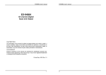
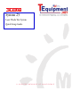
System 25 Laser Diode Test System Quick Setup Guide A GREATER MEASURE OF CONFIDENCE WARRANTY Keithley Instruments, Inc. warrants this product to be free from defects in material and workmanship for a period of 1 year from date of shipment. Keithley Instruments, Inc. warrants the following items for 90 days from the date of shipment: probes, cables, rechargeable batteries, diskettes, and documentation. During the warranty period, we will, at our option, either repair or replace any product that proves to be defective. To exercise this warranty, write or call your local Keithley representative, or contact Keithley headquarters in Cleveland, Ohio. You will be given prompt assistance and return instructions. Send the product, transportation prepaid, to the indicated service facility. Repairs will be made and the product returned, transportation prepaid. Repaired or replaced products are warranted for the balance of the original warranty period, or at least 90 days. LIMITATION OF WARRANTY This warranty does not apply to defects resulting from product modification without Keithley’s express written consent, or misuse of any product or part. This warranty also does not apply to fuses, software, non-rechargeable batteries, damage from battery leakage, or problems arising from normal wear or failure to follow instructions. THIS WARRANTY IS IN LIEU OF ALL OTHER WARRANTIES, EXPRESSED OR IMPLIED, INCLUDING ANY IMPLIED WARRANTY OF MERCHANTABILITY OR FITNESS FOR A PARTICULAR USE. THE REMEDIES PROVIDED HEREIN ARE BUYER’S SOLE AND EXCLUSIVE REMEDIES. NEITHER KEITHLEY INSTRUMENTS, INC. NOR ANY OF ITS EMPLOYEES SHALL BE LIABLE FOR ANY DIRECT, INDIRECT, SPECIAL, INCIDENTAL OR CONSEQUENTIAL DAMAGES ARISING OUT OF THE USE OF ITS INSTRUMENTS AND SOFTWARE EVEN IF KEITHLEY INSTRUMENTS, INC., HAS BEEN ADVISED IN ADVANCE OF THE POSSIBILITY OF SUCH DAMAGES. SUCH EXCLUDED DAMAGES SHALL INCLUDE, BUT ARE NOT LIMITED TO: COSTS OF REMOVAL AND INSTALLATION, LOSSES SUSTAINED AS THE RESULT OF INJURY TO ANY PERSON, OR DAMAGE TO PROPERTY. Keithley Instruments, Inc. 28775 Aurora Road • Cleveland, Ohio 44139 • 440-248-0400 • Fax: 440-248-6168 1-888-KEITHLEY (534-8453) • www.keithley.com Sales Offices: Bergensesteenweg 709 • B-1600 Sint-Pieters-Leeuw • 02-363 00 40 • Fax: 02/363 00 64 Yuan Chen Xin Building, Room 705 • 12 Yumin Road, Dewai, Madian • Beijing 100029 • 8610-8225-1886 • Fax: 8610-8225-1892 Tietäjäntie 2 • 02130 Espoo • Phone: 09-54 75 08 10 • Fax: 09-25 10 51 00 3, allée des Garays • 91127 Palaiseau Cédex • 01-64 53 20 20 • Fax: 01-60 11 77 26 Landsberger Strasse 65 • 82110 Germering • 089/84 93 07-40 • Fax: 089/84 93 07-34 Unit 2 Commerce Park, Brunel Road • Theale • Berkshire RG7 4AB • 0118 929 7500 • Fax: 0118 929 7519 1/5 Eagles Street • Langford Town • Bangalore 560 025 • 080 212 8027 • Fax: 080 212 8005 Viale San Gimignano, 38 • 20146 Milano • 02-48 39 16 01 • Fax: 02-48 30 22 74 New Pier Takeshiba North Tower 13F • 11-1, Kaigan 1-chome • Minato-ku, Tokyo 105-0022 • 81-3-5733-7555 • Fax: 81-3-5733-7556 2FL., URI Building • 2-14 Yangjae-Dong • Seocho-Gu, Seoul 137-888 • 82-2-574-7778 • Fax: 82-2-574-7838 Postbus 559 • 4200 AN Gorinchem • 0183-635333 • Fax: 0183-630821 c/o Regus Business Centre • Frosundaviks Allé 15, 4tr • 169 70 Solna • 08-509 04 600 • Fax: 08-655 26 10 13F-3. No. 6, Lane 99 Pu-Ding Road • Hsinchu, Taiwan, R.O.C. • 886-3-572-9077 • Fax: 886-3-572-9031 BELGIUM: CHINA: FINLAND: FRANCE: GERMANY: GREAT BRITAIN: INDIA: ITALY: JAPAN: KOREA: NETHERLANDS: SWEDEN: TAIWAN: 1/03 System 25 Laser Diode Test System Quick Setup Guide ©2001, Keithley Instruments, Inc. All rights reserved. Cleveland, Ohio, U.S.A. Second Printing, April 2003 Document Number: LIV-903-01 Rev. B Manual Print History The print history shown below lists the printing dates of all Revisions and Addenda created for this manual. The Revision Level letter increases alphabetically as the manual undergoes subsequent updates. Addenda, which are released between Revisions, contain important change information that the user should incorporate immediately into the manual. Addenda are numbered sequentially. When a new Revision is created, all Addenda associated with the previous Revision of the manual are incorporated into the new Revision of the manual. Each new Revision includes a revised copy of this print history page. Revision A (Document Number LIV-903-01) .................................................................. June 2001 Revision B (Document Number LIV-903-01) ................................................................. April 2003 All Keithley product names are trademarks or registered trademarks of Keithley Instruments, Inc. Other brand names are trademarks or registered trademarks of their respective holders. Safety Precautions The following safety precautions should be observed before using this product and any associated instrumentation. Although some instruments and accessories would normally be used with non-hazardous voltages, there are situations where hazardous conditions may be present. This product is intended for use by qualified personnel who recognize shock hazards and are familiar with the safety precautions required to avoid possible injury. Read and follow all installation, operation, and maintenance information carefully before using the product. Refer to the manual for complete product specifications. If the product is used in a manner not specified, the protection provided by the product may be impaired. The types of product users are: Responsible body is the individual or group responsible for the use and maintenance of equipment, for ensuring that the equipment is operated within its specifications and operating limits, and for ensuring that operators are adequately trained. Operators use the product for its intended function. They must be trained in electrical safety procedures and proper use of the instrument. They must be protected from electric shock and contact with hazardous live circuits. Maintenance personnel perform routine procedures on the product to keep it operating properly, for example, setting the line voltage or replacing consumable materials. Maintenance procedures are described in the manual. The procedures explicitly state if the operator may perform them. Otherwise, they should be performed only by service personnel. Service personnel are trained to work on live circuits, and perform safe installations and repairs of products. Only properly trained service personnel may perform installation and service procedures. Keithley products are designed for use with electrical signals that are rated Installation Category I and Installation Category II, as described in the International Electrotechnical Commission (IEC) Standard IEC 60664. Most measurement, control, and data I/O signals are Installation Category I and must not be directly connected to mains voltage or to voltage sources with high transient over-voltages. Installation Category II connections require protection for high transient over-voltages often associated with local AC mains connections. Assume all measurement, control, and data I/O connections are for connection to Category I sources unless otherwise marked or described in the Manual. Exercise extreme caution when a shock hazard is present. Lethal voltage may be present on cable connector jacks or test fixtures. The American National Standards Institute (ANSI) states that a shock hazard exists when voltage levels greater than 30V RMS, 42.4V peak, or 60VDC are present. A good safety practice is to expect that hazardous voltage is present in any unknown circuit before measuring. Operators of this product must be protected from electric shock at all times. The responsible body must ensure that operators are prevented access and/or insulated from every connection point. In some cases, connections must be exposed to potential human contact. Product operators in these circumstances must be trained to protect themselves from the risk of electric shock. If the circuit is capable of operating at or above 1000 volts, no conductive part of the circuit may be exposed. Do not connect switching cards directly to unlimited power circuits. They are intended to be used with impedance limited sources. NEVER connect switching cards directly to AC mains. When connecting sources to switching cards, install protective devices to limit fault current and voltage to the card. Before operating an instrument, make sure the line cord is connected to a properly grounded power receptacle. Inspect the connecting cables, test leads, and jumpers for possible wear, cracks, or breaks before each use. When installing equipment where access to the main power cord is restricted, such as rack mounting, a separate main input power disconnect device must be provided, in close proximity to the equipment and within easy reach of the operator. For maximum safety, do not touch the product, test cables, or any other instruments while power is applied to the circuit under test. ALWAYS remove power from the entire test system and discharge any capacitors before: connecting or disconnecting ca5/02 bles or jumpers, installing or removing switching cards, or making internal changes, such as installing or removing jumpers. Do not touch any object that could provide a current path to the common side of the circuit under test or power line (earth) ground. Always make measurements with dry hands while standing on a dry, insulated surface capable of withstanding the voltage being measured. The instrument and accessories must be used in accordance with its specifications and operating instructions or the safety of the equipment may be impaired. Do not exceed the maximum signal levels of the instruments and accessories, as defined in the specifications and operating information, and as shown on the instrument or test fixture panels, or switching card. When fuses are used in a product, replace with same type and rating for continued protection against fire hazard. Chassis connections must only be used as shield connections for measuring circuits, NOT as safety earth ground connections. If you are using a test fixture, keep the lid closed while power is applied to the device under test. Safe operation requires the use of a lid interlock. If The or ! is present, connect it to safety earth ground using the wire recommended in the user documentation. symbol on an instrument indicates that the user should refer to the operating instructions located in the manual. The symbol on an instrument shows that it can source or measure 1000 volts or more, including the combined effect of normal and common mode voltages. Use standard safety precautions to avoid personal contact with these voltages. The WARNING heading in a manual explains dangers that might result in personal injury or death. Always read the associated information very carefully before performing the indicated procedure. The CAUTION heading in a manual explains hazards that could damage the instrument. Such damage may invalidate the warranty. Instrumentation and accessories shall not be connected to humans. Before performing any maintenance, disconnect the line cord and all test cables. To maintain protection from electric shock and fire, replacement components in mains circuits, including the power transformer, test leads, and input jacks, must be purchased from Keithley Instruments. Standard fuses, with applicable national safety approvals, may be used if the rating and type are the same. Other components that are not safety related may be purchased from other suppliers as long as they are equivalent to the original component. (Note that selected parts should be purchased only through Keithley Instruments to maintain accuracy and functionality of the product.) If you are unsure about the applicability of a replacement component, call a Keithley Instruments office for information. To clean an instrument, use a damp cloth or mild, water based cleaner. Clean the exterior of the instrument only. Do not apply cleaner directly to the instrument or allow liquids to enter or spill on the instrument. Products that consist of a circuit board with no case or chassis (e.g., data acquisition board for installation into a computer) should never require cleaning if handled according to instructions. If the board becomes contaminated and operation is affected, the board should be returned to the factory for proper cleaning/servicing. LIV-903-01BTOC.fm Page i Wednesday, April 16, 2003 9:54 AM Table of Contents Introduction ................................................................................... 1 Standard system configurations .................................................... 1 Model s25-01000: General Purpose Laser Diode Test Measurement .............................................................. 1 Model s25-21230: Transmitter Module ................................. 2 Model s25-21210: 980nm Pump Module .............................. 2 Model s25-41220: High Power Pump Module ...................... 2 System block diagram ................................................................... 3 Installation ..................................................................................... 4 Connections ................................................................................... 6 Signal connections ................................................................. 6 Control connections ............................................................... 8 Power line connections .......................................................... 9 Power-up and checkout ................................................................. 9 Power-up ................................................................................ 9 Laser diode test resistor network ........................................... 9 Checkout procedure ............................................................. 10 Instrument programming ............................................................. 10 Model 2400/2420/2440 SourceMeter programming ........... 10 Model 2500 Dual Photodiode Meter programming ............. 12 Model 2510 TEC SourceMeter programming ..................... 14 List of Illustrations Figure 1 Figure 2 Figure 3 Figure 4 Figure 5 System block diagram ............................................................... Suggested rack mount locations ............................................... System signal connections ........................................................ System control connections ...................................................... Test resistor network ................................................................. 3 5 7 8 9 Congratulations! Congratulations on your purchase of Keithley’s System 25 Laser Diode Test System for testing of Laser Diode Modules (LDMs). In applications such as yours, our Laser Diode Test System has been proven to provide a complete LDM test solution, including control of the thermo-electric cooler (TEC), which is a critical part of LDM assemblies. In this quick setup guide, you will find information that will enable you to: • • • • • configure install make signal connections perform power-up and checkout begin programming The rest of this section provides an overview of our Laser Diode Test System. Your system is either a custom configuration or one of the following standard configurations: • • • • • • • • s25-01000 General Purpose Laser Diode Test System (previously LIV part number LIV-1) s25-21230 Transmitter Module Laser Diode Test System (previously LIV part number LIV-2) s25-21210 980nm Pump Laser Diode Test System (previously LIV part number LIV-3) s25-41220 High Power Pump Module Laser Diode Test System (previously LIV part number LIV-4) s25-02000 General Purpose Laser Diode Test System with Fixture TEC Control (previously LIV part number LIV-1-F) s25-22230 Transmitter Module Laser Diode Test System with Fixture TEC Control (previously LIV part number LIV-2-F) s25-22210 980nm Pump Laser Diode Test System with Fixture TEC Control (previously LIV part number LIV-3-F) s25-42220 High Power Pump Module Laser Diode Test System with Fixture TEC Control (previously LIV part number LIV-4-F) The basic configuration can be easily modified to allow for new connections or expansion with new measurement and control functions, such as other Keithley meters and switching systems. A demonstration software package, created in Visual Basic, provides you with a head start in programming your specific laser diode test system application. These configurations may include some or all of the following instruments: • Model 2400 SourceMeter® that drives the laser diode and acts as a modulator bias source in LDMs employing an integrated modulator. • Model 2440 5A SourceMeter Instrument that provides a 5A source and measure capability that makes it well suited for testing high power pump lasers. • Model 2500 Dual Photodiode Meter that uses a time-saving dual-channel design to facilitate simultaneous measurement of related parameters. • Model 2500INT Integrating Sphere that allows the system to make direct measurements of optical power, with results expressed in watts. • The Model 2510 TEC Sourcemeter that combines high-speed DC sourcing and measurement with the ability to control the operation of a laser diode module’s Thermo-Electric Cooler or TEC (also known as a “Peltier device”). • Model 2510-AT Autotuning TEC SourceMeter that adds autotuning capability using a modified Zeigler-Nichols algorithm. This allows you to determine P, I, and D (proportional, integral, and derivative) values for closed loop temperature control so you no longer need to determine the optimal values for these coefficients experimentally. Optoelectronic Solutions from Keithley Keithley offers a suite of products for electrical production test applications that support your need for accuracy and throughput. Other optoelectronic solutions available from Keithley include: • Model 2520 Pulsed Laser Diode Test System that combines high speed current pulsing with measurement capabilities for precision testing at earlier stages of production without the damaging effects of device heating. • The Model 4200 Semiconductor Characterization System that combines high resolution DC source and measurement with real-time plotting and analysis for material and device characterization and development. • Keithley’s RF/Microwave Signal Routing Systems for switching and conditioning of high data rate signals up to 40GHz. System 25 Laser Diode Test System Quick Setup Guide Introduction This guide provides basic information on setting up and using the System 25 Laser Diode Test System, which combines all the necessary DC measurement capabilities to test laser diode modules. For more detailed information on each of the instruments in the Laser Diode Test System, refer to the corresponding user’s manual supplied with each unit. Standard system configurations The standard system configurations below are supplied with all the cables and adapters required for communication, triggering, and connection to the device to be tested. Also included is all the necessary hardware for rack mounting the instruments. Model s25-01000: General Purpose Laser Diode Test Measurement This system is configured as a general purpose system. The system includes: • • • Model 2400 SourceMeter for laser drive and forward voltage measure. Model 2500 Dual Photodiode Meter for back facet detector measurement and front facet photo current. Model 2510 TEC SourceMeter for temperature control of the internal TEC module. 2 System 25 Laser Diode Test System Quick Setup Guide Model s25-21230: Transmitter Module This system is configured specifically for testing of transmitter laser module in the 1330nm to 1550nm range. The system includes: • • • • Model 2420 SourceMeter for laser drive and forward voltage measure. Model 2500 Dual Photodiode Meter for back facet detector measurement and front facet optical power. Model 2510-AT Autotuning TEC SourceMeter for temperature control of the internal TEC module. Model 2500INT Integrating Sphere with a cooled InGaAs detector and an FC/PC input connector for optical power measurement. Model s25-21210: 980nm Pump Module This system is configured specifically for testing of 980nm pump laser with an input current level of 3A or less. The system includes: • • • • Model 2420 SourceMeter for laser drive up to 3A and forward voltage measure. Model 2500 Dual Photodiode Meter for back facet detector measurement and front facet optical power. Model 2510-AT Autotuning TEC SourceMeter for temperature control of the internal TEC module. Model 2500INT Integrating Sphere with a silicon detector and an FC/PC input connector for optical power measurement. Model s25-41220: High Power Pump Module This system is configured specifically for testing of high power pump laser module with a 14xx wavelength. The system includes: • • • • Model 2440 SourceMeter for laser drive up to 5A and forward voltage measure. Model 2500 Dual Photodiode Meter for back facet detector measurement and front facet optical power. Model 2510-AT Autotuning TEC SourceMeter for temperature control of the internal TEC module. Model 2500INT Integrating Sphere with a germanium detector and an FC/PC input connector optical power measurement. System 25 Laser Diode Test System Quick Setup Guide 3 System block diagram Figure 1 shows an overall block diagram of the Laser Diode Test System. Components include: • • • • • • Model 2400/2420/2440 SourceMeter: sources current to the laser diode module and measures voltage across the device. Model 2500 Dual Photodiode Meter: Biases and measures currents from the two photodiode detectors. Model 2510/2510-AT TEC SourceMeter: Controls the TEC (thermo-electric cooler) power to maintain the laser diode module at the desired temperature. Model 2500INT Integrating Sphere: Provides optimal coupling of light from laser diode module to integral Ge, Si, or InGaAs photodiode detector (not included in Model LIV-1). Trigger Link: synchronizes instrument readings. GPIB: interfaces the instruments to the controlling computer. Figure 1 System block diagram GPIB GPIB Trigger Link 2510/ 2510-AT Thermistor Laser Diode 2400/2420/ 2440 TEC GPIB 2500 LDM* Fiber GPIB Computer 2500INT *LDM (Laser Diode Module) = Device Under Test 4 System 25 Laser Diode Test System Quick Setup Guide Installation The instruments for the Laser Diode Test System are shipped configured for bench-top use. If system rack mounting is desired, the necessary rack mounting kits are provided. Follow the steps below to rack mount the instruments. NOTE 1. 2. 3. See the documentation provided with the supplied Model 4288-1 and 4288-2 rack mount kits for more detailed information on attaching rack mount hardware. First determine the desired location of each instrument. Figure 2 shows suggested mounting locations. Be sure to allow sufficient air space above and below the instruments, as shown, for proper ventilation. Remove the handles and feet from the instruments, then attach the necessary rack mounting hardware. Slide the instruments into the rack, then secure them with four mounting screws. System 25 Laser Diode Test System Quick Setup Guide 5 Figure 2 Suggested rack mount locations Model 2510/ 2510-AT TEC SourceMeter 2510 TEC SourceMeter ® T V R I DISPLAY TOGGLE/ LOCAL CONFIG MENU POWER ON/OFF EDIT EXIT ENTER OUTPUT 1U (1.75”) Air Space 4-WIRE SENSE INPUT/ OUTPUT HI Model 2400, 2420, or 2440 SourceMeter 250V PEAK MEAS EDIT DISPLAY TOGGLE POWER V I 250V PEAK 2500 DUAL PHOTODIODE METER LO SOURCE Ω FCTN 1 2 3 REL FILTER LIMIT 6 7 8 250V PEAK CHANNEL SELECT I V RANGE 0 LOCAL DIGITS SPEED 1U (1.75”) Air Space 5V PEAK SourceMeter 9 STORE RECALL 4 5 EDIT TRIG SWEEP CONFIG MENU EXIT ENTER DISPLAY AUTO RANGE +/- TERMINALS ON/OFF OUTPUT FRONT/ REAR TOGGLE POWER MSR1 MSR2 RATIO DELTA SRC1 SRC2 RANGE 0 LOCAL 6 1 REL 7 DIGITS SPEED 2 3 FILTER LIMIT 8 9 STORE RECALL 4 TRIG +/- 5 EDIT AUTO SWEEP RANGE 0000 CONFIG MENU EXIT ENTER ON/OFF OUTPUT Model 2500 Dual Photodiode Meter 6 System 25 Laser Diode Test System Quick Setup Guide Connections Signal connections Using Figure 3 as a guide, make signal connections as follows: • • • NOTE Model 2400/2420/2440 SourceMeter — Connect the rear panel INPUT/OUTPUT and SENSE HI and LO terminals to the laser diode module using the supplied banana-tocoaxial adapters and BNC-to-alligator cables as shown. The instrument must be used in the 4-wire sense mode. Model 2500 Dual Photodiode Meter — Connect the INPUT jacks to the two photodiodes and/or integrating sphere using the supplied triax cables as shown. Connect the triax center conductor to the detector terminal labeled anode; triax outer shield (chassis ground) to the detector terminal labeled cathode. For the Model 2500INT integrating sphere, make direct connections using a triax cable and Model 6172 adapter. Note: ground connect mode must be enabled to use this configuration. (When using the demo software, channel 1 is the front facet, and channel 2 is the back facet.) Model 2510/2510-AT TEC SourceMeter — Connect the INPUT and OUTPUT terminals to the TEC and temperature sensor using the supplied Model 2510-CAB cable as shown. Additional cable configurations are available from Keithley Instruments, Inc. for other connections to the DUT. Contact your local sales representative for details. System 25 Laser Diode Test System Quick Setup Guide Figure 3 System signal connections INPUT/OUTPUT Connector Model 2510/2510-AT TEC SourceMeter 2510-CAB Connections (Assumes + Current Cools TEC) WARNING:NO INTERNAL OPERATOR SERVICABLE PARTS,SERVICE BY QUALIFIED PERSONNEL ONLY. CAT I OUTPUT ! Terminal Thermistor Thermistor + Thermistor Thermistor + TEC+ TEC+ TECTEC- IEEE-488 MADE IN U.S.A. INPUT (ENTER IEEE ADDRESS WITH FRONT PANEL MENU) F+ S+ S- F- F+ F- S+ S- ENABLE-DIG I/O ISOLATION FROM EARTH: 30V MAX. RS-232 TRIGGER LINK LINE FUSE SLOWBLOW 2.5A, 250V 120 ! LINE RATING 100-240VAC 50, 60 HZ 90VA MAX CAUTION:FOR CONTINUED PROTECTION AGAINST FIRE HAZARD,REPLACE FUSE WITH SAME TYPE AND RATING. 2510-CAB Cable Wire Color White Blue Yellow Red Black Green Brown Orange Center Conductor (Anode) + - - + Outer Shield (Cathode) INPUT BNC Cables Thermistor Note: Enable Ground Connect Mode TEC WARNING:NO INTERNAL OPERATOR SERVICABLE PARTS,SERVICE BY QUALIFIED PERSONNEL ONLY. RATINGS MAX 100V @ 20mA COMMON MODE 200V Triax Cables INPUT CHANNEL 1 IEEE-488 MADE IN U.S.A. (CHANGE IEEE ADDRESS WITH FRONT PANEL MENU) INPUT CHANNEL 2 DIGITAL I/O ! LINE RATING 50, 60Hz 60 VA MAX RATINGS MAX 100V @ 20mA LDM RS-232 TRIGGER LINK CAT I ! VOLTAGE SOURCE OUTPUT CHANNEL 1 VOLTAGE SOURCE OUTPUT CHANNEL 2 FUSE LINE 630 mAT (SB) 100 VAC 120 VAC 315 mAT (SB) 220 VAC 240 VAC 120 Laser Diode CAUTION:FOR CONTINUED PROTECTION AGAINST FIRE HAZARD,REPLACE FUSE WITH SAME TYPE AND RATING. Fiber Center Conductors 6172 Adapter SENSE HI INPUT/ OUTPUT HI INPUT/ OUTPUT LO Model 2500INT Integrating Sphere WARNING:NO INTERNAL OPERATOR SERVICABLE PARTS,SERVICE BY QUALIFIED PERSONNEL ONLY. 125V PEAK HI 5V PK 5V PEAK 125V PEAK MADE IN U.S.A. V, Ω, GUARD 5V PEAK LINE FUSE SLOWBLOW 3.15A, 250V LINE RATING GUARD SENSE 100-240VAC 50, 60HZ 220VA MAX LO 4-WIRE SENSE ! INPUT/ OUTPUT 250V PEAK IEEE-488 (ENTER IEEE ADDRESS WITH FRONT PANEL MENU) RS232 TRIGGER LINK CAUTION:FOR CONTINUED PROTECTION AGAINST FIRE HAZARD,REPLACE FUSE WITH SAME TYPE AND RATING. Model 2400/2420/2440 SourceMeter SENSE LO INTERLOCKDIGITAL I/O Model 2500 Dual Photodiode Meter 7 8 System 25 Laser Diode Test System Quick Setup Guide Control connections Refer to Figure 4 for the following control connections. GPIB connections Connect the rear panel IEEE-488 connectors of each instrument to the IEEE-488 interface of the next instrument, and then to the computer interface using the supplied Model 7007 GPIB cables. Trigger link connections Connect the rear panel TRIGGER LINK connectors of the Model 2400/2420/2440 and Model 2500 together using the supplied Model 8501 trigger link cable. Figure 4 System control connections WARNING:NO INTERNAL OPERATOR SERVICABLE PARTS,SERVICE BY QUALIFIED PERSONNEL ONLY. CAT I OUTPUT ! IEEE-488 MADE IN U.S.A. INPUT (ENTER IEEE ADDRESS WITH FRONT PANEL MENU) F+ S+ S- F- F+ F- S+ S- Model 2510/ 2510-AT TEC SourceMeter ENABLE-DIG I/O ISOLATION FROM EARTH: 30V MAX. RS-232 TRIGGER LINK LINE FUSE SLOWBLOW CAUTION:FOR CONTINUED PROTECTION AGAINST FIRE HAZARD,REPLACE FUSE WITH SAME TYPE AND RATING. WARNING:NO INTERNAL OPERATOR SERVICABLE PARTS,SERVICE BY QUALIFIED PERSONNEL ONLY. WARNING:NO INTERNAL OPERATOR SERVICABLE PARTS,SERVICE BY QUALIFIED PERSONNEL ONLY. RATINGS MAX 100V @ 20mA COMMON MODE 200V INPUT CHANNEL 1 LINE RATING 100-240VAC 50, 60 HZ 90VA MAX IEEE-488 Model 2500 Dual Photodiode Meter 2.5A, 250V 120 ! HI 5V PK 5V PEAK 125V PEAK MADE IN U.S.A. V, Ω, GUARD IEEE-488 MADE IN U.S.A. (CHANGE IEEE ADDRESS WITH FRONT PANEL MENU) INPUT CHANNEL 2 125V PEAK DIGITAL I/O 5V PEAK Model 2400/ 2420/2440 SourceMeter LINE FUSE SLOWBLOW 3.15A, 250V LINE RATING GUARD SENSE ! ! INPUT/ OUTPUT 250V PEAK 50, 60Hz 60 VA MAX ! VOLTAGE SOURCE OUTPUT CHANNEL 2 FUSE LINE 630 mAT (SB) 100 VAC 120 VAC 315 mAT (SB) 220 VAC 240 VAC IEEE-488 120 RATINGS MAX 100V @ 20mA VOLTAGE SOURCE OUTPUT CHANNEL 1 4-WIRE SENSE LINE RATING CAT I 100-240VAC 50, 60HZ 220VA MAX LO RS-232 TRIGGER LINK (ENTER IEEE ADDRESS WITH FRONT PANEL MENU) RS232 CAUTION:FOR CONTINUED PROTECTION AGAINST FIRE HAZARD,REPLACE FUSE WITH SAME TYPE AND RATING. TRIGGER LINK CAUTION:FOR CONTINUED PROTECTION AGAINST FIRE HAZARD,REPLACE FUSE WITH SAME TYPE AND RATING. Model 8501 Trigger Link Cable PC Computer IEEE-488 Interface INTERLOCKDIGITAL I/O TRIGGER LINK TRIGGER LINK Model 7007 GPIB Cables System 25 Laser Diode Test System Quick Setup Guide 9 Power line connections Connect instrument power line inputs to a grounded power outlet using the supplied line cords. Make certain that the power line voltage is within the range specified on the rear panel of each instrument. Power-up and checkout Power-up Turn on the power to all instruments, and verify that they all go through their normal powerup cycles. Note the IEEE-488 address that is shown on the bottom line of the display as part of the power-up cycle, for example: SCPI Addr = 25. Be sure to use that address in your program, or change the addresses to the desired settings. (Use the COMMUNICATION/GPIB selection in the main MENU.) Laser diode test resistor network Figure 5 shows a schematic diagram of a resistive network that can be used to check out your system. These resistors can be mounted in a shielded component box that is equipped with banana jacks for connections to 2400/2420/2440 INPUT/OUTPUT HI and LO, as well as two triax jacks for connections to the two Model 2500 INPUT jacks. Figure 5 Test resistor network Model 2400/2420/2440 SourceMeter Shielded Component Box 5kΩ INPUT/OUTPUT HI 100Ω 1kΩ INPUT/OUTPUT LO Model 2500 Dual Photodiode Meter Channel 2 Triax INPUT Channel 1 Triax INPUT 10 System 25 Laser Diode Test System Quick Setup Guide Checkout procedure Instruments can be checked for proper operation using the resistor network in Figure 5 as follows: • • Model 2400/2420/2440: Select SOURCE I, MEASURE V, then set the source current to +50mA. Turn on the output, then verify that the measured voltage is approximately +5V. Model 2500: Set the Model 2400/2420/2440 for SOURCE V, then set the output voltage to +5V. Turn on the output, then verify that the displayed Model 2500 channel 1 reading is approximately +5mA, and the displayed Model 2500 channel 2 reading is about +1mA. Instrument programming Several demonstration applications are provided on the software disk supplied with your Laser Diode Test System. Included is a Labview application and several Visual Basic (VB) applications specific to the type of interface card. These programs are fully functional and can be easily modified for your specific purposes. The following section provides details regarding the function of one of the VB applications provided. This information will aid your modification effort to taylor the applications to your specific needs. Model 2400/2420/2440 SourceMeter programming The code fragment below is a subroutine that sets up the SourceMeter for a laser diode current sweep while measuring laser diode voltage. Various operating modes are programmed as follows: • • • • • • • • • • • • • • • • • • • • Beeper: off Auto zero: off for maximum speed Remote sensing: on (4-wire connections) Terminals: rear Source function: current Start current: set during program execution (10mA minimum) Stop current: set during program execution (1A maximum) Step current: set during program execution ([start - step]/10 minimum) Current source mode: linear sweep, best fixed source range Source delay and NPLCs: set during program execution Sense function: concurrent functions disabled, voltage function enabled Voltage limit: 5V Voltage measurement range: 20V Data elements: both voltage and current, binary format SRQ: generate SRQ when buffer is full Arm source and count: immediate source, infinite count (bypass arm layer) Trigger source and lines: trigger link, line 1 input, line 2 output Source trigger: wait for input trigger before changing source, bypass first trigger Trigger output: output trigger after delay phase of SDM cycle Trigger delay: 0ms System 25 Laser Diode Test System Quick Setup Guide 11 Private Sub Setup24x0() 'Setup SourceMeter(tm) system commands: Call send(intKth24x0, ":syst:beep:stat off", intStatus) Call send(intKth24x0, ":syst:azer:stat off", intStatus) Call send(intKth24x0, ":syst:rsen 1", intStatus) 'disable beeper 'disable auto zero for speed 'enable four-wire measurements 'Call send(intKth24x0, ":display:enable off", intStatus) 'disable display Call send(intKth24x0, ":rout:term rear", intStatus) 'use rear terminals 'The source is configured for the sweep from textStartCurrent to textStopCurrent 'in steps defined by textStepCurrent. The sweep will use the best fixed range 'to prevent the inherent dicontinuities of range changing from being seen by the 'analysis code as kink. The source delay is also set to accommodate the cable and 'DUT capacitive loading. Call Call Call Call Call Call Call Call send(intKth24x0, send(intKth24x0, send(intKth24x0, send(intKth24x0, send(intKth24x0, send(intKth24x0, send(intKth24x0, send(intKth24x0, ":sour:func curr", intStatus) ":sour:curr:start " & textStartCurrent, intStatus) ":sour:curr:stop " & textStopCurrent, intStatus) ":sour:curr:step " & textStepCurrent, intStatus) ":sour:curr:mode sweep", intStatus) ":sour:swe:rang best", intStatus) ":sour:swe:spac lin", intStatus) ":sour:del " & txtSourceDelay, intStatus) ’source current 'set start (min.) 'set stop (max.) 'set step 'enable sweep mode 'use best fixed range 'select linear sweep 'set source delay 'The 24x0 will source current and measure the forward junction voltage 'across the laser diode. Both current and voltage will be passed to 'the analysis portion of the code. Call Call Call Call Call send(intKth24x0, send(intKth24x0, send(intKth24x0, send(intKth24x0, send(intKth24x0, ":sens:volt:nplc " & comboNPLC, intStatus) ":sens:func:conc off", intStatus) ":sens:func 'volt'", intStatus) ":sens:volt:prot 5", intStatus) ":sens:volt:range 20", intStatus) 'set NPLC per input param. 'turn off concurrent meas. 'sense voltage (V forward of LD) 'limit output voltage to 5V Call send(intKth24x0, ":form:elem volt,curr", intStatus) 'read both voltage and current Call send(intKth24x0, ":format:data sre;bord swap", intStatus) 'binary format Call send(intKth24x0, ":stat:meas:enab 512", intStatus) Call send(intKth24x0, "*sre 1", intStatus) 'mask "buffer full" byte 'mask "measurement summary bit" for SRQ 'Trigger layer is used to keep track of triggers from the front facet 'photodetector meter. The trigger count will be set later. Call send(intKth24x0, ":arm:sour imm", intStatus) 'bypass arm layer Call send(intKth24x0, ":arm:count inf", intStatus) Call Call Call Call Call send(intKth24x0, send(intKth24x0, send(intKth24x0, send(intKth24x0, send(intKth24x0, ":trig:clear", intStatus) ":trig:sour tlink", intStatus) ":trig:ilin 1", intStatus) ":trig:olin 2", intStatus) ":trig:input source", intStatus) Call send(intKth24x0, ":trig:outp del", intStatus) Call send(intKth24x0, ":trig:dir source", intStatus) Call send(intKth24x0, ":trig:delay 0", intStatus) End Sub 'clear triggers 'use trigger link 'input trigger on line 1 'output trigger on line 2 'wait for input trigger before 'changing source 'output trigger after soaking device 'new source current value 'bypass first input trigger 'set trigger delay to 0mS 12 System 25 Laser Diode Test System Quick Setup Guide Model 2500 Dual Photodiode Meter programming The code fragment below is a subroutine that sets up the Model 2500 to measure current from both photodiodes using the 20mA range on both channels. Operating modes are set as follows: • • • • • • • • • • • • • • • • • • • Data format: channel 1 and channel 2 current, binary format Channel 1 NPLCs: set during program execution (0.01 to 10) Channel 1 current range: 20mA (set during program execution) Channel 1 voltage bias source: 10V range, value checked and set during program execution Channel 1 source delay: 0 Channel 1 ground connect mode: enabled Channel 2 NPLCs: set during program execution (0.01 to 10) Channel 2 current range: 20mA (set during program execution) Channel 2 voltage bias source: 10V range, value checked and set during program execution Channel 2 source delay: 0 Channel 2 ground connect mode: enabled Arm source: immediate (bypass arm layer) Arm count: 1 Arm direction: acceptor (wait for trigger event) Trigger source and lines: trigger link, line 1 output, line 2 input Trigger input: wait for trigger before measuring Output trigger: trigger after settling Trigger event bypass: do not bypass on first pass through trigger layer Data store format: channel 1 and channel 2 currents System 25 Laser Diode Test System Quick Setup Guide 13 Private Sub Setup2500() 'General instrument configuration Call send(intKth2500, ":form:elem curr1,curr2", intStatus) Call send(intKth2500, ":form:data sre;bord swap", intStatus) 'Call send(intKth2500, ":syst:key 16", intStatus) ' ******* Configure Channel 1 of 2500 'output only current readings 'binary format 'toggle display to show both channels ********** 'Setup sense circuitry for 20mA range Call send(intKth2500, ":sens1:curr:nplc " & comboNPLC, intStatus) Call send(intKth2500, ":sens1:curr:rang " & textN1CurrRange, intStatus) 'Setup source to bias the front facet photodiode. Call send(intKth2500, ":sour1:volt:range 10", intStatus) If textN1Bias > 10 Then: textN1Bias = 10 If textN1Bias < -10 Then: textN1Bias = -10 Call send(intKth2500, ":sour1:volt " & textN1Bias, intStatus) Call send(intKth2500, ":sour1:delay 0", intStatus) Call send(intKth2500, ":sour1:gcon 1", intStatus) ' ******* Configure Channel 2 of 2500 'set NPLC using input Param. '20mA range 'set range to 10V 'set bias output 'set source delay to zero 'enable ground connect relay ********** 'Setup sense circuitry for 20mA range Call send(intKth2500, ":sens2:curr:nplc " & comboNPLC, intStatus) Call send(intKth2500, ":sens2:curr:rang " & textN2CurrRange, intStatus) 'Setup source to bias the photodiode with 5V. Call send(intKth2500, ":sour2:volt:range 10", intStatus) If textN2Bias > 10 Then: textN2Bias = 10 If textN2Bias < -10 Then: textN2Bias = -10 Call send(intKth2500, ":sour2:volt " & textN2Bias, intStatus) Call send(intKth2500, ":sour2:delay 0", intStatus) Call send(intKth2500, ":sour2:gcon 1", intStatus) 'set NPLC using input Param. '20mA range 'set range to 10V 'set bias output 'set source delay to zero 'enable ground connect relay 'Setup Trigger Model: Bypass both arm layers and use trigger 'layer to synch with trigger from 24x0. Call Call Call Call Call Call Call Call Call Call send(intKth2500, send(intKth2500, send(intKth2500, send(intKth2500, send(intKth2500, send(intKth2500, send(intKth2500, send(intKth2500, send(intKth2500, send(intKth2500, ":arm:sour imm", intStatus) ":arm:coun 1", intStatus) ":arm:dir acc", intStatus) ":trig:clear", intStatus) ":trig:sour tlink", intStatus) ":trig:ilin 2", intStatus) ":trig:olin 1", intStatus) ":trig:input sense", intStatus) ":trig:outp sense", intStatus) ":trig:dir acceptor", intStatus) Call send(intKth2500, ":trac:feed calc3,calc4", intStatus) End Sub 'bypass arm layer 1 'set scan count 'wait for trigger event 'clear triggers 'use trigger link 'input trigger on line 2 'output trigger on line 1 'wait for input trigger before 'output trigger after setting 'do not bypass on first pass 14 System 25 Laser Diode Test System Quick Setup Guide Model 2510 TEC SourceMeter programming The code fragment shown below is a subroutine that conditionally sets up the following Model 2510 operating modes: • • • • • Current protection limit: 1A Sensor type: thermistor Thermistor sensor current range: auto Thermistor sensor measurement range: 10kΩ Temperature setpoint: set during program execution Private Sub comboTempOnOff_Click() If comboTempOnOff.Text = "ON" Then Call send(intKth2510, "*rst", intStatus) Call send(intKth2510, ":sens:curr:prot:lev 1.0", intStatus) ' 1A current limit Call send(intKth2510, ":sens:temp:tran ther", intStatus) ' Thermistor sensor type Call send(intKth2510, ":sens:temp:curr:auto on", intStatus) ' Auto sensor current range Call send(intKth2510, ":sens:temp:ther:range 1e4", intStatus) ' 10k ohm sensor resistance range Call send(intKth2510, ":sour:temp:spo " & comboTempSetPoint.Text, intStatus) ' Program setpoint Call send(intKth2510, ":outp on", intStatus) ' Turn on output Call send(intKth2510, ":meas:res:ac?", intStatus) ' Get TEC AC resistance Call enter(strData, 100, intLength, intKth2510, intStatus) txtTECRes.Text = strData Call send(intKth2510, ":outp on", intStatus) Else Call send(intKth2510, "*rst", intStatus) End If End Sub Specifications are subject to change without notice. All Keithley trademarks and trade names are the property of Keithley Instruments, Inc. All other trademarks and trade names are the property of their respective companies. Keithley Instruments, Inc. 28775 Aurora Road • Cleveland, Ohio 44139 • 440-248-0400 • Fax: 440-248-6168 1-888-KEITHLEY (534-8453) • www.keithley.com Sales Offices: Bergensesteenweg 709 • B-1600 Sint-Pieters-Leeuw • 02-363 00 40 • Fax: 02/363 00 64 Yuan Chen Xin Building, Room 705 • 12 Yumin Road, Dewai, Madian • Beijing 100029 • 8610-8225-1886 • Fax: 8610-8225-1892 Tietäjäntie 2 • 02130 Espoo • Phone: 09-54 75 08 10 • Fax: 09-25 10 51 00 3, allée des Garays • 91127 Palaiseau Cédex • 01-64 53 20 20 • Fax: 01-60 11 77 26 Landsberger Strasse 65 • 82110 Germering • 089/84 93 07-40 • Fax: 089/84 93 07-34 Unit 2 Commerce Park, Brunel Road • Theale • Berkshire RG7 4AB • 0118 929 7500 • Fax: 0118 929 7519 1/5 Eagles Street • Langford Town • Bangalore 560 025 • 080 212 8027 • Fax: 080 212 8005 Viale San Gimignano, 38 • 20146 Milano • 02-48 39 16 01 • Fax: 02-48 30 22 74 New Pier Takeshiba North Tower 13F • 11-1, Kaigan 1-chome • Minato-ku, Tokyo 105-0022 • 81-3-5733-7555 • Fax: 81-3-5733-7556 2FL., URI Building • 2-14 Yangjae-Dong • Seocho-Gu, Seoul 137-888 • 82-2-574-7778 • Fax: 82-2-574-7838 Postbus 559 • 4200 AN Gorinchem • 0183-635333 • Fax: 0183-630821 c/o Regus Business Centre • Frosundaviks Allé 15, 4tr • 169 70 Solna • 08-509 04 600 • Fax: 08-655 26 10 13F-3, No. 6, Lane 99, Pu-Ding Road • Hsinchu, Taiwan, R.O.C. • 886-3-572-9077 • Fax: 886-3-572-9031 BELGIUM: CHINA: FINLAND: FRANCE: GERMANY: GREAT BRITAIN: INDIA: ITALY: JAPAN: KOREA: NETHERLANDS: SWEDEN: TAIWAN: © Copyright 2003 Keithley Instruments, Inc. Printed in the U.S.A. 2/03