1
Installation Manual VMI® PULSE’R Prestige 2 / Prestige 2+
1
Important information:
This manual explains how to install and maintain VENTILAIRSEC's VMI® PULSE’R Prestige 2 / Prestige 2+
units
Certain operations must only be carried out by qualified staff and must not be carried out by the user
under any circumstances.
May 2015 edition
2
Table of contents:
1
GENERAL INFORMATION ......................................................................................................................... 4
1.1
1.2
2
DESCRIPTION OF THE APPLIANCE ............................................................................................................. 6
2.1
2.2
2.3
2.4
3
OVERVIEW ................................................................................................................................................ 6
TECHNICAL CHARACTERISTICS ........................................................................................................................ 7
DIMENSIONS.............................................................................................................................................. 8
PRESENTATION OF THE REMOTE CONTROL ..................................................................................................... 10
INSTALLATION ....................................................................................................................................... 13
3.1
3.2
3.3
3.4
3.5
3.6
3.7
3.8
3.9
3.10
3.11
4
ABOUT THIS MANUAL .................................................................................................................................. 4
SAFETY INSTRUCTIONS ................................................................................................................................. 4
PREPARATION .......................................................................................................................................... 13
LOCATION ............................................................................................................................................... 13
VENTILATION OPENINGS ............................................................................................................................. 14
HOUSINGS............................................................................................................................................... 15
ROOF OUTLET .......................................................................................................................................... 17
DUCT NETWORK ....................................................................................................................................... 17
SUMMARY OF THE INSTALLATION ................................................................................................................. 19
ELECTRICAL CONNECTION ........................................................................................................................... 20
REMOTE CONTROL .................................................................................................................................... 20
AIR EXTRACTION POINTS............................................................................................................................. 20
DOOR UNDERCUTS .................................................................................................................................... 21
COMMISSIONING ................................................................................................................................... 21
4.1
4.2
4.3
4.4
4.5
4.6
4.7
4.8
4.9
PROPER COMPLETION CHECKS ..................................................................................................................... 22
POWERING UP FOR THE FIRST TIME / PAIRING ................................................................................................ 22
ACCESSING THE INSTALLER MODE/CONFIGURATION MODE ................................................................................ 22
SETTING THE RATED SPEED/FILTER DURATION ................................................................................................. 24
CONSUMPTION AND OPERATING TIME SCREEN ................................................................................................ 24
TROUBLESHOOTING................................................................................................................................... 25
VERSION SCREEN ...................................................................................................................................... 26
EXITING THE INSTALLER MODE ..................................................................................................................... 26
INITIAL SETTINGS ...................................................................................................................................... 26
5
GETTING STARTED ................................................................................................................................. 28
6
CARE ...................................................................................................................................................... 28
6.1
6.2
6.3
6.4
6.5
6.6
7
FILTER .................................................................................................................................................... 28
RESETTING THE FILTER COUNTER .................................................................................................................. 29
BATTERIES ............................................................................................................................................... 29
SD CARD ................................................................................................................................................. 29
AIR INLETS AND OUTLETS ............................................................................................................................ 30
CLEANING/CHECKING ................................................................................................................................ 30
GLOSSARY .............................................................................................................................................. 31
3
1
General information
1.1 About this manual
Danger/Important information. This symbol
indicates important
information that must be observed to prevent any risks of physical
injury and/or damage to equipment.
Must only be done by qualified staff.
Can be done by the user.
Read this manual carefully to ensure optimal performance of the
appliance.
VENTILAIRSEC declines all liability if the instructions given in this
manual are not followed.
In this manual, the word "Premises" refers to the space to be
ventilated, whether it be a house, offices or public premises.
1.2 Safety instructions
1.2.1 Installation
The appliance must be handled and installed with means adapted
to its weight.
The appliance must be installed by qualified staff.
Once the appliance has been installed, it must be put into
operation quickly to avoid condensation building up.
1.2.2 Use
This appliance is not intended for use by people (including children)
with reduced physical, sensory or mental capacities, or by people
with no experience or knowledge of the appliance, unless they are
monitored by or have received instructions from someone
responsible for their safety when using the appliance.
Make sure that children do not play with the appliance.
This appliance is designed exclusively for ventilating and circulating
air and no other fluid.
Do not insert anything in the ventilation ducts and do not obstruct
the air inlets and air outlets.
Do not place anything on the appliance.
The VMI® unit must never be turned off.
In case of abnormal functioning, contact the machine's installer.
4
1.2.3 Care and maintenance
Disconnect the power supply before all interventions (except for
maintenance that can be done by the user and defined below) and
make sure that it cannot be accidentally reset.
The user may only change the appliance's filter, the remote
control's batteries and clean the air inlets and outlets, providing
they follow the instructions given in this installation manual (part
6 Care).
All other maintenance operations must be carried out by qualified
staff.
The user must not attempt to repair any breakdowns.
If the power cable is damaged, it must be replaced by the
manufacturer, its after sales service or by similarly qualified people
to avoid any danger.
You are advised to record all care and maintenance operations on
the service history sheet at the end of the manual.
1.2.4 Transformation
The appliance must not be modified. All components must be
replaced by a professional and with genuine parts from the
manufacturer.
1.2.5 End-of-life
Before removing the appliance, power it down.
Do not burn the appliance. Certain components
may release toxic gases when they are burnt.
Remove the batteries from the remote control
and take the components to a recycling
collection point.
Take the product to a recycling collection point.
The product must not be disposed of with
household waste.
5
2
Description of the appliance
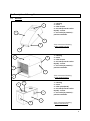
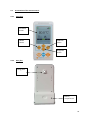
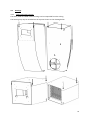
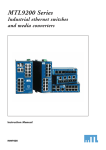
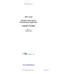
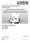
2.1
Overview
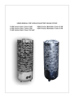
1 – Housing
2 – Cover
3 – Filter drawer
4 – Air inlet (from the roof or
façade) - suction
5 – Air outlet (to premises) positive ventilation
5
2
1
*Non-contractual drawing
*Galbé model housing
4
3
2
5
4
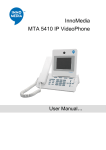
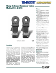
1 – Housing
2 – Cover
3 – Filter drawer
4 – Air inlet (from the roof or
façade) - suction
5 – Air outlet (to premises) positive ventilation
1
*Non-contractual drawing
*Cube model housing
3
3
2
5
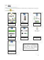
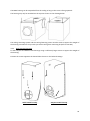
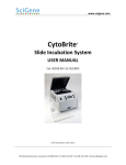
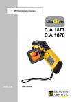
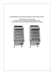
1 – Housing
2 – Cover
3 – Filter plate (BLUE)
4 – Air inlet (from the roof or
façade) - suction
5 – Air outlet (to premises) positive ventilation
1
4
*Non-contractual drawing
*Maxi model housing
6
2.2
Technical characteristics
2.2.1
Operation
Single phase 230 VAC, 50 Hz
Maximum output for Galbé, Cube and Compact model housings: 1140 W
Maximum output for MAXI model housing: 2220 W
Electrical protection factor: IPX2
Ambient operating temperature: -5°C/60°C
Remote Control - VMI® Communication Radio Frequency: 868 MHz
2.2.2
Structure
Weight: 11 kg (Galbé and Compact models) 10 kg (Cube model) 11.9 kg (Maxi model)
Housing electrolytic zinc coated steel 1.5 mm thick - epoxy powder-coated paint RAL9010
Cover: ABS AE UL94V0 3 mm thick 3 mm
Grade F7 and G4 filters
2 connection pieces for 160 mm diameter ducts
2.2.3
Performance
Air preheating: 12°C, 15°C, 18°C
Maximum flow rate for Compact model: 170 m3/h
Maximum flow rate for Galbé/Cube models: 218 m3/h
Maximum flow rate for Maxi model: 400 m3/h
Recommended size of premises to be ventilated:
o from 59 m² to 140 m² (Galbé, Cube models),
o from 32 m² to 136 m² (Compact model)
o from 141 m² to 307 m² (Maxi model)
(Average renewal rate 0.5 vol/h, unchanging ceiling height of 2.5 m)
7
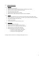
Housing
Galbé
Compact
250
Allow for room to
change the filter
250
250
Cube
160
180
600
2.3.1
Dimensions
475
2.3
250
300
8
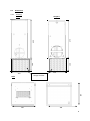
MAXI :
320
320
Allow for room to
change the filter
520
2.3.2
264
Remote control
Hole for wall
mounting
65.80
9
2.4
2.4.1
Presentation of the remote control
Front face
TFT colour
screen
MODE
button
Validation
button
Navigation
arrows
2.4.2
Rear face
Fixing point
Battery
compartment
10
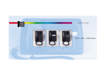
2.4.3
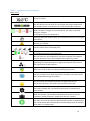
Displays
2.4.3.1 Presentation of the screens
To make it easy to use, the remote control has 7 interface screens. To change screens, you just need
to press the
button.
88 d/200
Main screen
Set temperatures'
setting screen
Filter status screen
Control mode setting
screen
Options activation
screen
System test activation
screen
Please note that the presentation of
these screens is non-contractual.
Certain parameters may be different
depending on the settings and the
indoor and outdoor environment.
Installer settings
screen
11
2.4.3.2 Presentation of the pictograms
Main screen
Ambient temperature measured in the living area where the remote
control is located.
Air quality indicator according to humidity. The more the cursor is to the
left, the drier the air; the more it is to the right, the more humid the air.
The middle position corresponds to the most comfortable conditions.
Filter status display.
When the filter is orange, we recommend that you order a new filter
from your installer.
To change the filter (see chapter 6.1)
Manual mode activated.
Warning: when this mode is active, the automatic functions are no longer
operational.
Malfunctioning detected.
Contact your installer.
Radio reception quality indicator. If the reception is bad, move your
remote control closer to the VMI® unit.
Battery indicator for the 2 AA LR6 batteries
To change the batteries (see chapter 6.3)
Indicator for the minimum set temperature for preheating the blown air.
N.B. The lower the set temperature, the lower the power consumption.
You are advised to cut the set temperature during the hot season.
Fan operating speed indicator. In automatic mode, the speed may vary
depending on various parameters to adjust the ventilation flow rate to
the requirements of the premises.
High outdoor humidity indicator. The intelligent VMI® unit adjusts its air
flow rate to stop air that is too humid entering the premises.
Ventilation cooling mode activated (automatically activated). The air flow
rate is increased to cool down the premises and make your environment
more comfortable during the summer.
Turbo heat mode activated (automatically activated). The air flow rate is
increased when the outside temperature is higher than the set
temperature in winter. This means that you recover free heat.
Boost mode activated (activated by the user via the specific screen). With
this mode, the flow rate is increased for 30 minutes to renew the air
more quickly.
Holiday mode activated (activated by the user via the specific screen).
With this function, the ventilation and preheat functions are set to a
minimum ("freeze protection" mode) when the user is absent.
STANDBY mode activated (automatically activated).
The VMI® unit turns at minimum speed and desactivates air preheating if
the outside temperature exceeds the maximum temperature threshold or
if the VMI® unit malfunctions.
12
3
Installation
The appliance must be installed by qualified staff.
The VMI® unit must be installed in compliance with the regulations in force: DTU 68.3.
Electrical connections must be made in accordance with the regulations in force: NFC 15-100.
For safety aspects, please refer to part 1.2 Safety rules.
When installing the VMI® Prestige 2 unit, you must also have a Prestige 2 radio remote control
3.1 Preparation
Before installing the appliance, remove the three foam wedges surrounding the motor inside the
housing.
Open the machine's cover by removing the 4 flat head screws.
Remove the foam wedges and the remote control.
Close the cover again by screwing down the 4 flat head screws.
Fix the two plastic collars supplied:
3.2
One on the inlet and the other on the outlet. The same is true for the Compact versions. (For
the Cube model housing, fix the collar plate (Ref. No. AE 003) using the 4 specific fixing points).
Use the D3.9 L9.5 screws supplied.
Use the pre-drilled holes on the housing. Do not pierce the housing.
Location
The appliance must be installed away from water and frost.
13
The appliance must be installed so that it can be easily accessed for care and maintenance operations.
If the appliance is placed in the roof space, you must allow for a trap door of at least 50x50 cm. This
trap door must not be placed in a cupboard.
Place the VMI® unit in a central position to limit the length of the ducts as much as possible and so
that the ducts leading to the ventilation openings are of similar length.
3.3
Ventilation openings
3.3.1
3.3.2
Location
Place the ventilation openings in the premises to ventilate.
It is preferable to place the openings in centrally-located rooms (corridor, atrium, landing, etc.)
that do not generate humidity or odours.
Do not place ventilation openings in damp rooms (bathroom, kitchen, WC).
Place the openings 20 cm away from obstacles (wall, beam, etc.).
Installation
Trace the part to cut out: a 160 mm diameter circle.
Cut the material with a suitable tool.
Insert the sleeve and then the ventilation opening.
14
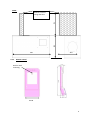
3.4
Housings
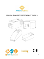
3.4.1 Ceiling-mounted housings
The Cube, Galbé and MAXI model housings can be suspended from the ceiling.
The housing may only be attached via the 4 points shown on the drawing below.
15
The MAXI housing can be suspended from the ceiling as long as the cover is facing upwards.
The housing may only be attached via the 4 points shown on the drawing below.
The ceiling-mounting system and the ceiling fastening points must be sized to support the weight of
the housing. Ventilairsec can provide you with a ceiling chain mounting kit (Ref. No. AE 020).
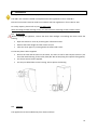
3.4.2 Wall-mounted housings
Fix the Compact and Galbé model housings using 3 sufficiently large screws to support the weight of
the housing.
Position the screws opposite the slotted holes shown on the below drawings.
Galbé model housing
Compact model housing
16
The Cube model housing can also be fixed to a wall using the Cube wall-mounting frame (Ref. No.
AE 019). To do this, first fix the frame to the wall using an appropriate fixing system, then insert the
two tongues into one of the rear parts of the housing as shown in the following drawing by rotating
the housing a quarter turn:
3.4.3 Free-standing housing
The housing can be free-standing as long as it is positioned for easy access to the filter. You are not
advised to place it on its cover.
Make sure that the support is stable and correctly sized for the weight of the appliance.
3.5
3.6
Roof outlet
The roof outlet must be sized for a maximum suction loss of 50 Pa at RS+2 (see 4.9 Initial
settings – Rated speed RS).
The roof outlet must be placed as close as possible to the VMI® housing.
Set the roof outlet up as indicated in its installation and operating manual and according to
the type of roof.
Make sure that it is correctly oriented to prevent rain from entering the duct network.
For air inlets on the building façade:
Bore through the wall following standard practice.
Use a rainproof grille on the outside and optionally an insect grille if it can be accessed to be
cleaned.
Duct network
Use insulated ducts, 160 mm diameter.
Use as few bends as possible.
Place the duct as straight as possible.
Make sure the network is carefully sealed, from the roof outlet to the ventilation openings.
17
3.6.1
Connections
Fix a duct to the roof outlet using a clamping collar. Make sure the connection is correctly
sealed.
Cut the duct from the outlet to the right length and fix it to the VMI® unit's inlet collar. Use a
clamping collar and make sure it is correctly sealed.
Fix new ducts (one per ventilation opening) to the sleeves using clamping collars. Make sure
the connection is correctly sealed.
(4V and 6V types) Cut the ducts from the ventilation openings' sleeves to the right length and
fix them to the two coaxial ends of the connecting tee. Both ducts must be of similar length
and as short as possible. Use clamping collars and make sure the connections are correctly
sealed.
(4V and 6V types) Fix a duct to the third end of the connecting tee. Use a clamping collar and
make sure it is correctly sealed.
(4V and 6V types) Cut the duct from the tee to the right length and fix it to the VMI® unit's
outlet collar. Use a clamping collar and make sure it is correctly sealed.
Cut the duct from the ventilation opening's sleeve to the right length and fix it to the VMI®
unit's outlet collar. Use a clamping collar and make sure it is correctly sealed.
18
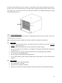
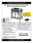
3.7
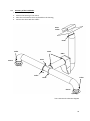
Summary of the installation
1. Put the sleeves in place,
2. Position the housing in the centre,
3. Place the roof outlet as close as possible to the housing,
4. Connect the ducts with the collars.
Roof
outlet
Collar
Collar
Collar
VMI®
Collar
Sleeve
Opening
Tee
Collar
Collar
Collar
Sleeve
Opening
*non-contractual schematic diagram
19
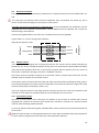
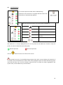
3.8 Electrical connection
The appliance must be connected by a professional in compliance with the French standard NFC 15100.
This step must only be done when the other installation steps are finished. This avoids any risk of
electric shocks when installing the various parts of the system.
The VMI® unit must be connected to a dedicated line. On the switchboard, the installation must be
equipped with a 16 A bipolar circuit breaker, a 30 mA differential circuit breaker and a means for
disconnecting in the fixed line.
Connect the supplied cable to the mains via a sealed junction box (not supplied).
Type of cable: 3 x 1.5 mm² with ground conductor.
Brown
Phase
Yellow/Green
Ground
Blue
Neutral
Home
network part
VMI® part
Single phase 230 VAC, 50 Hz
Sealed box
3.9 Remote control
If the premises are equipped with a heating thermostat, the remote control should preferably be
placed next to it. If not, it should be placed in a living area, as it measures the relative ambient humidity
and controls the ventilation flow rate. It must never be placed above a radiator, close to a source of
cold, under a ventilation opening or closed in a cupboard or drawer.
The remote control can either be placed on a horizontal surface or fixed to the wall via the 2.5 mm
diameter hole on the back of the remote control.
If the remote control is fixed to the wall, check the radio connection before installing the fixing system.
Any obstacles between the remote control and the VMI® unit reduce the maximum range of the radio
communication (walls, metal objects, floors, etc.).
If you are using the system to cure damp, place the remote control in the room to be treated so that
the VMI® unit can adjust its ventilation flow rate to the humidity rate in the room.
3.10 Air extraction points
All rooms in the premises, even if they have no windows or do not have an outside wall, must be
equipped with a natural air extraction point (trickle vent, wall duct). If they do not, extraction points
must be made following standard practice.
To correctly adjust the extraction grilles, distribute 90% of the air blown into the premises between all
of the rooms.
Measures must be taken to avoid gas backdrafts in the room from the exhaust pipes of gas appliances
or other open fire appliances (for the duct fans and the partition wall fans).
20
All other extraction devices installed under other regulations (e.g. gas appliances) must not be altered.
3.11 Door undercuts
Undercuts must be made under all doors in the premises. The space required between the floor and
the bottom of the door is as follows:
4
1 cm for all doors including the kitchen door if it has at least 2 access doors.
2 cm for the kitchen door if it has only one access door and for all doors to rooms equipped
with an appliance connected to the gas.
Commissioning
The appliance must be installed by qualified staff.
21
4.1 Proper completion checks
In accordance with the DTU 68.3, a visual inspection must be carried out after the installation to check
that:
The sizing specifications are respected,
The installation is safe (electrically, mechanically),
The system's components are in good condition,
The remote control and other components can be accessed for maintenance.
Make sure that the foam wedges inside the machine have been removed.
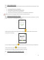
4.2 Powering up for the first time / Pairing
Open the battery compartment on the rear of the remote control and insert the batteries. Close the
battery compartment. The following screen appears:
Update the date and time on the remote control using the
control asks for the pairing.
Turn on the VMI® unit and press the
If the connection fails, press
buttons. Wait until the remote
button within 30 seconds after turning on the VMI® unit.
to start the procedure again.
Tip: move closer to the VMI® unit if you have problems connecting
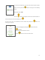
4.3
Accessing the installer mode/configuration mode
22
To correctly set the VMI® unit, you must use the remote control's installer
mode. To do this, press the
screen:
button until you get to the following
The installer code is 1919.
Press the
buttons to change the value of the selected number. To
confirm and move on to the next number, press
.
The value of the code is only checked on the last number after pressing the
following screen appears:
Choose your language by pressing the
button. The
buttons then press
to confirm.
Check that the date and time are correct.
Use the
button to return to the main screen.
23
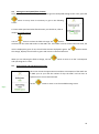
4.4 Setting the rated speed/filter duration
Once you are in the installer mode, you should first get the rated speed setting screen. If not, press the
button as many times as necessary to get to the following
screen:
To know what speed and what filter duration you should set, refer to
chapter 4.9 Initial settings.
200
Use the
buttons to select the field to change. The
button
confirms the new value and sends it to the VMI® unit. If the VMI® unit has received the new value, the
value is displayed in green. If not, the old value remains displayed in green. The
the change, displays the old value in green and returns to the field selection.
When you are selecting the field to change, use the
and operating time" screen.
4.5
button cancels
button to move on to the "consumption
Consumption and operating time screen
This screen shows the approximate cumulative consumption of the VMI® unit
in kWh year on year and the number of days the VMI® unit has been in
operation since it was commissioned.
Use the
button to move on to the troubleshooting screen.
days
24
4.6
Troubleshooting
This screen helps the installer with troubleshooting.
Important: a test must be run to update the fault codes. Only
the probes are automatically updated.
Once the test has finished, the system status is displayed
Motor status
Preheat status
VMI® unit's probe status
This probe is not active in this
version
Remote control's probe status
N.B. Probe No. 2 is always displayed even if it is not present on the VMI® unit. If there is only one
probe, no status is shown for the second probe.
Normal operation
Use the
Abnormal operation.
button to move on to the version screen.
The VMI® unit test is for troubleshooting purposes only and in no way replaces the expertise of
an installer. We recommend that installers have a fully-equipped repair case with them during repair
visits and that they carry out the necessary electrical tests to confirm the failure signalled by the
system. Also, certain failures may conceal others.
25
4.7
Version screen
This screen shows the VMI® unit's and the remote control's software and
hardware versions. This information may be requested for technical monitoring
or assistance.
Use the
4.8
button to move on to exit the installer mode.
Exiting the installer mode
Press the
buttons to select "yes" or "no", and
selection.
If "yes" is selected, the main screen appears.
If "no" is selected, the "language/date" screen appears.
to confirm the
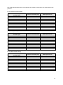
4.9 Initial settings
Parameters:
In the installer mode, you can set the 2 parameters shown in the following table.
Parameter
Description
Factory
setting
In situ setting
Rated speed
(RS)
Speed at which the VMI® unit
operates in automatic mode in
normal conditions.
V9
To be adjusted for the volume to
ventilate to ensure a renewal
rate of 0.5 volume/hour.
See table below
Max filter
Filter usage duration before filter
change warning is displayed
200 days
The setting depends on the
premises'
surrounding
environment.
Choosing the Rated Speed:
26
The rated speed should be set to correspond to the volume to ventilate or the surface area of the
premises.
For the Galbé and Cube models:
Surface area of the space to
ventilate* (m²)
0 to 24
25 to 61
62 to 74
75 to 80
81 to 90
91 to 97
98 to 122
123 to 148
149 to 164
165 to 174
For the Compact model:
Surface area of the space to
ventilate* (m²)
0 to 16
17 to 24
25 to 31
32 to 40
41 to 48
49 to 56
57 to 68
69 to 80
81 to 96
97 to 136
Volume to ventilate (m3)
Rated speed to set*
0 to 60
60 to 154
155 to 184
185 to 200
201 to 224
225 to 242
243 to 306
307 to 370
371 to 410
411 to 436
V1
V2
V3
V4
V5
V6
V7
V8
V9
V10
Volume to ventilate (m3)
Rated speed to set*
0 to 40
41 to 60
61 to 80
81 to 100
101 to 120
121 to 140
140 to 170
171 to 200
201 to 240
241 to 340
V1
V2
V3
V4
V5
V6
V7
V8
V9
V10
For the MAXI model housing:
Surface area of the space to
Volume to ventilate (m3)
ventilate* (m²)
0 to 87
0 to 217
88 to 131
220 to 327
132 to 157
330 to 392
158 to 182
395 to 455
183 to 207
457 to 517
208 to 232
520 to 580
233 to 257
582 to 642
258 to 282
645 to 705
283 to 307
707 to 767
308 to 320
770 to 800
* for premises with an unchanging ceiling height of 2.5 m.
Rated speed to set*
V1
V2
V3
V4
V5
V6
V7
V8
V9
V10
27
5
Getting started
In compliance with DTU 68.3, the installer/contractor must:
6
Clearly explain the reasons for ventilating (Indoor Air Quality),
Explain the technical aspects of the appliance,
Explain the operation of the appliance,
Give specific information on the appliance (always in operation during the intended periods,
do not obstruct the air inlets and outlets, clearance under doors, etc.),
Remind the user of the care and maintenance instructions given in the installation and
operating manuals and that the ventilation must never be stopped
Give the user the operating manual.
Care
6.1 Filter
The VMI® PULSE’R Prestige 2 unit is equipped with a grade G4 filter.
The VMI® PULSE’R Prestige 2 + unit is equipped with a grade F7 filter.
(For 3V or 4V installations, the VMI® PULSE’R Prestige 2 + unit is also equipped with a G4 sleeve filter)
To ensure optimum air quality and correct functioning of the VMI® unit, the filter must be regularly
changed.
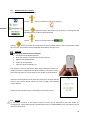
Changing the filter
Order a new filter from VENTILAIRSEC.
Access the VMI® unit.
Manually unscrew the 2 plastic head screws on the filter compartment.
Remove the old filter.
WARNING: do not insert anything in the machine apart from the new filter.
Insert the new filter.
o For a G4 filter: the blue part of the filter must be facing the outside of the machine.
o For an F7 filter: the tab on the filter must be pointing towards the outside of the VMI®
unit.
The new filter must be quickly inserted after the old one is removed.
Screw down the 2 plastic head screws.
Reset the filter counter (number of days used) on the remote control (see 6.2 Resetting the
filter counter, Care section).
WARNING: when changing the filter, only the drawer must be removed. You may get an electric shock,
get burnt or cut yourself if you open the housing.
28
6.2 Resetting the filter counter
This screen appears in the user mode:
Use the
buttons to select the "Reset" pictogram:
00 d/200
Use the
button to confirm, after which the "new filter?" message and the
YES/NO buttons (on NO by default) appear.
Use the
buttons to choose YES or NO:
Use the
button to confirm and if YES is active, then the filter counter reset request will be taken
into account. The number of days displayed automatically changes to 0.
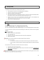
6.3
Batteries
Changing the remote control's batteries
You need 2 new LR6/AA batteries.
With your thumbs, slide the cover down to open it.
Remove the dead batteries.
Insert the new batteries.
Close the cover by sliding it up.
The batteries must not be thrown away with household rubbish. To
dispose of them in compliance with local standards, take them to your
local collection point or return them to your retailer or manufacturer.
Important: If the operation lasts more than 2 minutes, the time must be
reset on the remote control. When you start up again, the following
screen appears:
If the time has not been reset, it will display the last time saved.
6.4 SD card
An SD card is inserted in the remote control. It must not be removed by the user under any
circumstances, unless requested by a professional partner of VENTILAIRSEC. This card collects various
data for maintenance.
29
6.5 Air inlets and outlets
Every 6 months, remove the dust from the ventilation openings and the air extraction grilles with a
clean, dry cloth and a small brush.
6.6 Cleaning/checking
Operation that cannot be done by the user.
6.6.1 Cleaning
The machine must be thoroughly cleaned once a year (preferably in autumn), either as part of a
maintenance contract or when requested by the user.
Cleaning the machine
Cut all power to the VMI® unit before intervening and make sure that it cannot be
accidentally reset.
Open the machine's cover by removing the 4 flat head screws.
Remove the dust from the fan's wheel using a blower or a dry brush.
Remove the dust from the resistors using a blower or a dry brush.
Wipe the inside of the housing with a clean cloth.
Close the cover again by screwing down the 4 flat head screws.
6.6.2 Checks
To make sure the appliance remains effective, it is important to check the following points:
The condition of the duct system. Clean or change it if necessary.
The roof outlet or the suction grille must be clear and not obstructed by anything (nest, leaves,
etc.). If it is obstructed, clean it following the safety rules.
The various air passages (openings, grilles, ventilation under doors). They must be clear and
not reduced in size.
30
7
Glossary
Air quality: assessment of the state of the ambient air according to a scale measuring the rate of
concentration of pollutants.
Condensation: physical phenomenon resulting in the appearance of water droplets when warm air
comes into contact with a cold surface.
Cut-off temperature: see 4.9 Initial settings.
Door undercuts: removing a small part at the bottom of a door so that the air can flow underneath it.
Flow rate (air/ventilation): volume of blown air over a certain period.
Load loss: organ or irregularity impeding the flow of air.
Pairing: creating a pair, i.e. two communicating appliances recognise each other. In this case, the
VMI® unit and the remote control recognise each other.
Positive ventilation: air injected into the premises.
Preheat temperature: temperature at which the VMI® unit preheats the air blown into the premises
if the temperature of air it draws in is lower.
Premises: space to ventilate - house, offices, public premises, etc.
Relative humidity: Rate of humidity in the air as a percentage.
Renewal rate: number of times the air in the premises is renewed every hour.
RS: Rated speed. The VMI® set speed for the volume to be ventilated.
VMI®: Positive Input Ventilation.
31