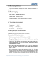
1
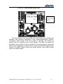
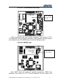
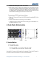
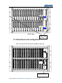
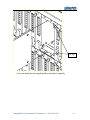
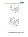
User Manual of
FT-50S (6U) PCM Multiplexer
B2
CH
B1
CH
A9
1
1
1
2
2
2
3
3
3
1
A8
CH
CH
A7
CH
A6
CH
A5
CH
A4
CH
A3
CH
A2
CH
A1
CH
MST-A
MST-B
PWR-A
CH
1
1
1
1
1
1
1
1
2
2
2
2
2
2
2
2
2
3
3
3
3
3
3
3
3
3
4
4
4
4
4
4
4
4
4
4
4
4
5
5
5
5
5
5
5
5
5
5
5
5
6
6
6
6
6
6
6
6
6
6
6
6
7
7
7
7
7
7
7
7
7
7
7
7
8
8
8
8
8
8
8
8
8
8
8
8
+5V
ALM
SAL
NB
T/R
RUN
ALM
SAL
NB
T/R
RUN
-5V
-48V
MASK
MASK
MUTE
MUTE
Test
Test
OFF/ON
B3
R
FT-50S
CH
CH
CH
CH
CH
CH
CH
CH
CH
CH
CH
CH
+5V
1
1
1
1
1
1
1
1
1
1
1
ALM
ALM
2
2
2
2
2
2
2
2
2
2
2
2
3
3
3
3
3
3
3
3
3
3
3
3
NML
NML
4
4
4
4
4
4
4
4
4
4
4
4
USE
USE
5
5
5
5
5
5
5
5
5
5
5
5
6
6
6
6
6
6
6
6
6
6
6
6
7
7
7
7
7
7
7
7
7
7
7
7
8
8
8
8
8
8
8
8
8
8
8
8
-5V
-48V
OFF/ON
1
R
FT-50S
B4
B5
B6
B7
B8
B9
B10
B11
B12
B13
B14
B15
Ring-A
Ring-B
PWR-B
Nanjing Photel Communication Technology Co., Ltd.
Nanjing Photel Communication Technology Co., Ltd. 1999-2011
1
Table of Contents
1
1.1
1.2
1.3
1.4
1.5
1.6
1.7
1.8
Brief Introduction ....................................................................................................... 4
High density .................................................................................................................... 4
Abundant Access Interfaces ............................................................................................ 4
Powerful Net Management System................................................................................. 5
D/I (drop/insert) function ................................................................................................ 5
PABX function ................................................................................................................ 5
Optional OPT optical transmission unit .......................................................................... 5
Supper Reliability............................................................................................................ 5
Unique ID card design .................................................................................................... 6
2
2.1
2.2
Operation Principle and Configuration................................................................. 6
Operation Principle ......................................................................................................... 6
System Configuration...................................................................................................... 7
2.2.1
Power supply card................................................................................................ 8
2.2.2
Ring supply card ................................................................................................... 9
2.2.3
Master card............................................................................................................ 9
2.2.4
Channel card ......................................................................................................... 9
2.3
Application of Equipment ............................................................................................. 10
2.4
Equipment composition and operation.......................................................................... 12
2.4.1
Equipment composition ..................................................................................... 12
2.4.2
Functions of unit cards and operation instructions ........................................ 12
2.4.2.1 -48V Power supply card................................................................................ 12
2.4.2.2 AC/DC Power Supply Card .......................................................................... 13
2.4.2.3 Ring supply card ........................................................................................... 14
2.4.2.4 Master card.................................................................................................... 15
2.4.2.5 PDH Optical card .......................................................................................... 16
2.4.2.6 Access sub-channel card ............................................................................... 17
3
3.1
3.2
Technical Specification .......................................................................................... 29
Electrical Characteristics of 2M Interface..................................................................... 29
FXS and FXO Interface and Signaling ......................................................................... 30
3.2.1
FXO ...................................................................................................................... 30
3.2.2
FXS....................................................................................................................... 30
3.3
Ringing.......................................................................................................................... 31
3.3.1
Remote ringing current ...................................................................................... 31
3.3.2
Ringing testing .................................................................................................... 31
3.4
Audio Interfaces............................................................................................................ 31
3.4.1
2-wire tone ........................................................................................................... 31
3.4.2
4-wire tone ........................................................................................................... 32
3.4.3
Magneto interface............................................................................................... 33
3.4.3.1 Ordinary magneto interface........................................................................... 33
3.4.3.2 Carrier wave magneto audio interface........................................................... 33
3.4.4
Hotline telephone................................................................................................ 34
3.4.5
Synchronous data interface .............................................................................. 34
3.4.5.1 G.703 interface.............................................................................................. 34
3.4.5.2 Data interface ................................................................................................ 34
3.4.5.3 N*64K V.35 interface ................................................................................... 34
3.4.6
Asynchronous data interface ............................................................................ 34
3.4.7
10/100M Ethernet Data interface ..................................................................... 35
3.4.8
PDH Optical card................................................................................................ 35
Nanjing Photel Communication Technology Co., Ltd. 1999-2011
2
3.5
3.6
3.7
3.8
Monitoring Interface ..................................................................................................... 36
Power Supply ................................................................................................................ 36
Operation Environment................................................................................................. 36
The principle of test function ........................................................................................ 36
4
Sub-Rack Dimensions............................................................................................. 37
5
5.1
Installation.................................................................................................................. 37
Install the rack ............................................................................................................... 37
5.1.1
Install the rack to the 19inch shelf.................................................................... 37
5.1.2
Functional card configuration............................................................................ 38
5.1.3
Plug the cards ..................................................................................................... 39
5.1.4
Cable configuration ............................................................................................ 42
5.1.4.1 Take off the back cover................................................................................. 42
5.1.4.2 The power interface....................................................................................... 44
5.1.4.3 The alarm interface ....................................................................................... 45
5.1.4.4 The NMS system interface............................................................................ 46
5.1.4.5 Access channel interface ............................................................................... 46
5.1.4.6 Cable connector............................................................................................. 52
Nanjing Photel Communication Technology Co., Ltd. 1999-2011
3
1 Brief Introduction
FT-50S (6U) PCM Multiplexer adopts 6U high standard 19" rack. It supports
multiple analog and data access, and fiber/electronic integration. The maximum
64Kbps access capacity of FT-50S (6U) PCM Multiplexer is 192, and the
maximum E1 access capacity is 64.
FT-50S (6U) PCM Multiplexer can connect with other transmission
equipment through its optical interface or standard E1 interface. It can realize
point to point communication by E1 or optical interface; and it can execute D/I
(drop/inset) function through its own 64E1 cross connection matrix; and it can
realize PABX function with its relay card; and it can have online test functions
including remote channel circuit test and subscriber line test.
FT-50S (6U) PCM Multiplexer is provided with a powerful NMS system, by
which the operating status of the network can be monitored in real time and the
functions including malfunction locating, time slot reassignment and online test
can be performed easily. The NMS information transmission: the FT serial
equipment can be cascaded through RS232 port if the equipment is located in
the same room, and they can be connected through TS0 time slot of E1 when the
equipment is located in different rooms. The NMS console can be connected with
the devices directly via RS232 port or ETH port, and graphical interface NMS,
command line NMS or SNMP NMS can be realized, which can improve the
efficiency of network management into a high level.
FT-50S (6U) PCM Multiplexer has the following characteristics:
1.1 High density
The system capacity is 192 64K channels. The system can access up to
maximum 64 E1 interface.
1.2 Abundant Access Interfaces
FT-50S (6U) PCM Multiplexer supports different types of user services:
64Kbps codirectional data and N×64Kbps synchronous data interface,
10/100M Ethernet interface, RS232 and RS485 asynchronous data interface,
FXO, FXS, Hotline, Magneto, Carrier wave magneto interface and 2/4-wire
E&M interface, etc.
Nanjing Photel Communication Technology Co., Ltd. 1999-2011
4
1.3 Powerful Net Management System
It is convenient to set cross connection and the level of analog interface,
and read the devices’ settings by NMS
Automatic online test function can realize level test and signaling test for
analog interface, functional test for data interface, functional tests of A/B
ground, short circuit for 2-wire subscribers, it is very convenient to locate
malfunction quickly and correctly through the NMS.
1.4 D/I (drop/insert) function
The D/I function can be configured by software, which make it very
flexible to drop or insert channels.
1.5 PABX function
The PABX function can be realized by the Relay card, the relay card will
support China No.1 signaling, No.7 signaling, PRI signaling and V5
signaling.
1.6 Optional OPT optical transmission unit
The OPT Optical transmission card can be selected by customer to
reduce the equipment cost of the whole transmission system. The E1
interfaces of the equipment can be transmitted via optical interface. 8 E1
and 4 ETH will be transmitted via the OPT card, therein 4E1 will be
transmitted directly, and the other 4E1 will enter 64E1 cross connection of
the system.
1.7 Supper Reliability
All key cards adopt redundant backup and support hot swappable,
including power supply cards, ring supply cards and master cards.
The FT-50S (6U) PCM Multiplexer adopts advanced circuit design and
modular structure design, it uses low power consumption, high reliable
components, and all functional cards support hot swap as well.
Nanjing Photel Communication Technology Co., Ltd. 1999-2011
5
1.8 Unique ID card design
The ID card is fixed in the shelf; it can identify the equipment’s ID, and
store the configuration data file and dynamic operating data. So if changing
other functional cards will not influence NMS to identify the equipment, which
makes it more stable during switching master control card.
2 Operation Principle and Configuration
2.1 Operation Principle
FT-50S (6U) PCM Multiplexer conforms to ITU G.703, G.704, G.706 and
G.715 standards, each Sub-Rack contains up to 24 Access Channel cards,
and each access channel cards hold 8 access channels, so each Sub-Rack
contains 192 access channels.
FT-50S (6U) PCM Multiplexer performs the digitalizing processing for the
analogue audio signals, the transmitting system will multiplex the digital
signals into standard E1 digital frame (these digital signals include the
digitized signal from analogue interfaces and digital signal from the data
interfaces.), multi-channel E1 signal will proceed 64K cross connection in the
cross connection matrix. The output interface of the system is standard E1 or
PDH optical interface. The receiving terminal will synchronize and decode
the 2M signals, and proceed the reverse progress, and send the analogue
audio signal or digital signal to the user.
NMS management can be performed for both remote equipment and
local equipment. The master card (MST card) will provide two RS232
network interface. The NMS connection mode is very flexible, the local
equipment can be cascade connected through RS232 interface, and the
remote equipment can be connected by TS0 channel of E1 interface or
private NMS channel. Every product has an exclusive serial number, and
this number is used as identification code by NMS. The NMS platform can
connect with any node of the network, and FT-50S (6U) equipment can be
connected in the “Chain” or “Tree” topology. The NMS console can
simultaneously monitor the status of any equipment that manufactured by
our company in the same network.
The power supply cards are mutually backup, to provide power of +5V,
-5V for the system. The ring supply cards are also mutually backup which
Nanjing Photel Communication Technology Co., Ltd. 1999-2011
6
generate the ring signal for FXS, HOT, MAG, Carrier wave interface and the
test function.
The Master cards are also hot backup, and it will not influence the phone
communication during switching the master cards.
2.2 System Configuration
FT-50S (6U) PCM Multiplexer can be configured with two power supply
cards, two ring supply cards, two master cards (you may use one of them
only to reduce the cost) and 24 Access Channel cards (the types and
number of channel card are optional). The number and type of the Access
Channel cards is according to the requirements. The system configuration is
as detailed below.
Nanjing Photel Communication Technology Co., Ltd. 1999-2011
7
channel card×24
Master card×2
Ring supply×2
Power supply×2
Front view of FT-50S (6U)
2.2.1Power supply card
One power supply card can be chosen to reduce the cost or two
power cards to get more reliability. The two power cards are hot backup
mutually, so no switch time needed.
Nanjing Photel Communication Technology Co., Ltd. 1999-2011
8
2.2.2Ring supply card
One ring supply card can be selected to reduce the cost or two ring
cards to get more reliability. Because the ring card produces more heat
when it is powered on, so the system will automatically switch off the ring
card when the system doesn’t need ring.
2.2.3Master card
One or two master card mode can be selected by user. The system
will be more reliability when using two master cards, the master cards are
back up mutually, no switch time need.
2.2.4Channel card
There are 24 channel card slots in the FT-50S (6U) PCM Multiplexer.
One channel card can hold two sub-channel cards (any types of
sub-channel card). Each sub-channel card has 4 audio ports or 4 64Kbps
data ports or 4E1 ports or one FV35 port or one Ethernet port.
Two different types of sub-channel cards can be inserted into the
same channel card. The channel card that inserted with E1 sub-channel
card can be only plugged into slot A1 to A8 slots. And the other channel
card can be plugged to any slot of the equipment.
For sub-channel card 2
For sub-channel card 1
CH
1
2
3
4
5
6
7
8
Channel access card
Nanjing Photel Communication Technology Co., Ltd. 1999-2011
9
There are eight LED on the panel of the channel card. The LED 1- 4
are corresponding to sub-channel card 1, and the LED 5 - 8 are
corresponding to sub-channel card 2. Each LED has two colors: red and
green. In application of 64Kbps services such as audio and low speed
data communication, when the remote channel is absent, the LED will be
red. When the remote channel is online, the red color will disappear. The
LED will flash in green color when E or M of audio cards is effective, or
the data card is running with low speed data.
If the sub-channel card is 4 E1 card, the LED will never be green.
When the E1 interface produces LOSS or FA, the LED will be red.
If the sub-channel card is N×64Kbps card, the LED will not be red.
When its data is running, the led will be green.
If the sub-channel card is Ethernet card, the LED will not be red.
When the Ethernet interface is connected successfully, the led will be
green.
2.3 Application of Equipment
FT-50S (6U) PCM Multiplexer has the ability to build up flexible network.
FT-50S (6U) PCM Multiplexer has flexible networking ability. The basic
mode is point-to-point over optical fiber or over transmission network. It also
can be used as Drop/Insert equipment. The transmission media between
local station and remote station can be optical fiber, satellite or microwave
equipment.
FT-50S
FT-50S
FT-50S
FT-50S
R
R
FT50S
FT50S
E1
Transmission
network
E1
R
R
FT50S
FT50S
Bay Networks
Router
1 2 3
4 5 6
Phone
7 8 9
*
AV
8 #
AV
PBX
Nanjing Photel Communication Technology Co., Ltd. 1999-2011
PC
10
Communicating over transmission network
FT-50S
FT-50S
FT-50S
FT-50S
R
OPT
R
FT50S
FT50S
R
R
FT50S
FT50S
Bay Networks
Router
1 2 3
4 5 6
Phone
AV
7 8 9
*
8 #
AV
PBX
PC
Point-to-point communicating over optical fiber
FT-50S
FT-50S
R
FT50S
E1
E1
R
FT50S
AV
1 2 3
Phone
PC
4 5 6
7 8 9
*
8 #
As a Drop/Insert equipment
Nanjing Photel Communication Technology Co., Ltd. 1999-2011
11
2.4 Equipment composition and operation
2.4.1Equipment composition
FT-50S (6U) PCM Multiplexer consists of the following unit cards:
Power supply card, ring supply card, Master card, and Channel card. In
normal situation, the Sub-Rack, power supply card and master card are
basic configuration, and other access cards are optional according to the
requirements. An ID card must be plugged into the backboard card.
There are many types of data stored in the ID card. FT-50S (6U) must be
equipped with ID card.
2.4.2Functions
of
unit
cards
and
operation
instructions
2.4.2.1
-48V Power supply card
+5V
-5V
OFF/ON
-48V
R
FT-50S
PT-50S
The main functions of the power supply card are voltage conversion and
supplying power to the system. The equipment has two power supply card
positions for mutual backup (one single power supply card can provide power for
the system independently). The input is -48V; the output is +5V and -5V.
There are 6 LED lights (3 LED for red color, 3 LED for green color) on the
power supply card for -48V +5V and -5V. When the -48V is normal the LED is
green, when there is no -48V power input, the LED will be red. When +5V is
normal the LED is green, when +5V is abnormal the LED is red. When -5V is
normal the LED is green, when -5V is abnormal the LED is red. The red light
means alarm. The NMS terminal can mask the alarm states.
Nanjing Photel Communication Technology Co., Ltd. 1999-2011
12
2.4.2.2
AC/DC Power Supply Card
PT-50S
+5V
-5V
-48/
220
R
PT-50S
FT-50S
AC/DC power supply card can connect with -48V DC power
input from the rear power connector, and it also can connect with
220AC power input from the front panel. AC and DC power can
provide power independently, and they also can work at the same
time for mutual backup. The functions of this AC/DC power supply
are the same as those of -48V power supply card.
Nanjing Photel Communication Technology Co., Ltd. 1999-2011
13
2.4.2.3
Ring supply card
ALM
NML
USE
The ring supply card generates ring for FXS, HOT, CRR, MAG cards and
testing modules. There are two ring supply card slots for ring supply card; they
work in mutual back up. The ring supply card generates ringing signal of 75V,
25HZ and 30W sine wave.
There are three LED in the panel of the ring supply card. The ALM will be
red when the card has fault. If the card is in normal state, the NML led will be lit
when the system needs the ring supply running. Only one ring supply card works
at one time, and the other is in the backup state. USE led will be green when the
card supplies ringing signal.
If no ringing signal needed, all LED in the panel of the ring supply card will
be off.
Nanjing Photel Communication Technology Co., Ltd. 1999-2011
14
2.4.2.4
Master card
Test control unit
ALM
SAL
NB
T/R
RUN
MASK
MUTE
Test
FT-50S (6U) PCM Equipment can be equipped with two Master cards (one
master card mode can be selected), it will realize the following functions: perform
2048×2048 non-blocking time slot cross connection, perform testing of all
analogue and data channels, and perform net management function. The master
card mainly consists of one CPU unit, time slot cross connection unit and
channel testing unit. The test control unit is used for testing the audio ports and
E/M signaling.
Main functions of a Master card:
•
Indicating various alarm information, and running status.
•
Monitoring communication, reporting the system status to NMS console,
and receiving control information from the NMS console.
•
When it is synchronized with the external clock, the clock is TTL level
and is connected via a coaxial cable, and the external clock must be
2.048 MHz.
•
There are 5 LED on the panel of the master card. The indicators are
defined as follows:
ALM
Red
If any alarm occurred in the FT-50S (6U), the ALM will be
red unless the alarm status is masked by NMS.
SAL
Yellow
The SAL will be lit when the FT-50S (6U) is in the
downloading state. For example, in progress of power on
Nanjing Photel Communication Technology Co., Ltd. 1999-2011
15
and the data setting by NMS.
NB
Yellow
Lit when the master card is switching to the backup card.
T/R
Green
Lit when communication with NMS.
RUN
Green
RUN led in the running master card will be lit, and the led in
the backup card will be off.
•
User shuts the alarm bell and the ground signal by pressing the MASK
button, but the alarm signals will recover when the new alarm occurs.
•
The MUTE key is the key with lock. If the key is pressed down, the alarm
bell and the alarm ground signal will never appear.
•
There is a TEST socket on the panel of the master card, which can be
controlled by the NMS; user can test the analog access channels with
PCM meter. The channel number for testing is selected by NMS. The
PCM meter is connected to TEST jack for testing (the testing module
should be selected to realize this function).
•
The communication between the equipment and the NMS console is via
the RS232 serial port. The RS232 connector is a RJ45 socket mounted
on the backboard. There are two RS232 ports on the backboard. They
can be connected in two directions.
•
The Master card performs time slot cross connection function, which can
accomplish non-blocking cross connection for 64×E1 time slots. The
cross connection matrix is 2048×2048.
2.4.2.5 PDH Optical card
CH
1
2
3
4
5
6
7
TX
OPT
RX
8
The PDH Optical card adopts PDH optical transmission mode, its access
Nanjing Photel Communication Technology Co., Ltd. 1999-2011
16
capacity is 8 E1 and 4 10/100M Ethernet interfaces. Herein 4E1 will enter FT-50S
(6U) equipment’s cross connection matrix, and the other 4E1 will be output
directly through rear connectors, which will be used by other access equipment.
And the NMS can read the optical alarms of this optical card and the E1 alarms,
and the NMS also can mask the warning status.
The PDH optical card has two optical interfaces, which support hot
swappable function, the optical module adopt the popular SFP optical module,
which can be hot swappable, and it is convenient for maintenance.
The PDH optical card’s first sub-channel card is the position (near to the front
panel) that EOO ETH sub-channel card can be inserted, and the second
sub-channel card position can insert any type of sub-channel cards, such as E1
card, analog card and data card.
There are 8 two color LED lights, LED 5-8 is corresponding to the second
sub-channel card, and the LED status definition is the same as the normal
channel card. LED1-4 will indicate the status of optical interface, ETH and E1
interface. Herein 4 green LED is used as LINK indicators for 4 ETH interfaces,
LED 1, 2 will indicate the receiving status of the first and second optical
interfaces, when the optical synchronization, the corresponding LED is off, when
the optical signal loss, the corresponding red LED is on; LED 3 indicates the
alarm status of the first and second transparent E1 interface, when these two E1
interfaces has not alarms, the LED will be off, when the both E1 interfaces have
alarms, the LED is lit, when the first E1 has alarm, and the second E1 doesn’t
have alarms, the LED will flash slowly, and the second E1 has alarms, and the
first E1 doesn’t have alarms, the LED will flash quickly; LED 4 indicates the alarm
status of the third and forth transparent E1 interface, when these two E1
interfaces has not alarms, the LED will be off, when the both E1 interfaces have
alarms, the LED is lit, when the third E1 has alarm, and the forth E1 doesn’t have
alarms, the LED will flash slowly, and the forth E1 has alarms, and the third E1
doesn’t have alarms, the LED will flash quickly.
2.4.2.6
Access sub-channel card
There are many types of Access sub-channel cards. FXS and
FXO are for extension of subscriber line of PBX; 2/4-wire tone is for
analogue trunk of PBX, MODEM or other analog line; the hotline
interface, magneto phone interface and 2100 carrier wave interface
are used for the special line application. 64Kbps data interface for
low rate data communication, such as RS232 and V.35 etc; In
Nanjing Photel Communication Technology Co., Ltd. 1999-2011
17
addition, the V.35 interface card and 10/100M Ethernet access card
can access N×64Kbps data, the N can be 1 to 31.
2.4.2.6.1 FXO card
This position
is for testing
module
The main function of FXO card is used to connect with the subscriber lines of
the switch. It is for extension of subscriber line of PBX. It is used with FXS card
usually and for MODEM or analogue trunk of PBX .Its functions include: tone
encoding and decoding, 2wire/4wire conversion, ringing signal testing, signaling
decoding, etc. Each FXO card contains 4 channels. There is a position for Test
module, it can test the audio level and the signaling of every channel and find
that if the FXO interface is connected to the PBX firmly. The NMS System
controls the testing process. More details please refer to the NMS manual.
Nanjing Photel Communication Technology Co., Ltd. 1999-2011
18
2.4.2.6.2 FXS card
This
position is
for testing
module
The main function of FXS card is to accomplish the encoding and decoding
of audio signal, 2-wire/4-wire conversion, power feed for subscriber, transmitting
ringing signal, over-voltage protection for outdoor user lines, etc. Each FXS card
contains 4 channels. The FXS card is usually connected with FXO, for example,
the local interface is FXO, and then the remote interface must be FXS. There is a
position for Test module. The module is used for testing the audio level, the
signaling of every channel and outdoor twisted cable. User can test the outdoor
twisted cable whether the cable is shorted, opened and grounded. The NMS
System controls the testing process. More details please refer to the NMS
manual.
Nanjing Photel Communication Technology Co., Ltd. 1999-2011
19
2.4.2.6.3 4-wire E&M audio card
This position
is for testing
module
The main functions of the 4-wire E&M audio card include voice encoding and
decoding, and providing independent audio transmitting/receiving channel,
accessing E and M signal. Each card contains 4 channels. This interface is
usually used for connection with a tone Modem. The NMS can adjust the
attenuation of the channel. There is a position for Test module that for testing the
audio level of transmitting, the audio level of receiving and the E/M signal of each
channel. The NMS System controls the testing process. More details please
refers to the NMS manual.
Nanjing Photel Communication Technology Co., Ltd. 1999-2011
20
2.4.2.6.4 Co-directional data card
This position
is for testing
module
Each Co-directional data card contains 4 channels. They conform to ITU-T
G.703 standard. The test modules are used for testing whether the data channels
are working correctly. The NMS System controls the testing process.
2.4.2.6.5 RS232 card
This position is for
testing module
Each RS232 data card contains 4 channel asynchronous RS232 data
interfaces. They conform to ITU-T V.24/V.28 standard. The test module is for
Nanjing Photel Communication Technology Co., Ltd. 1999-2011
21
testing whether the data channels are working correctly. The NMS System
controls the testing process.
2.4.2.6.6 N×64Kbps FV.35 card
This position
is for testing
module
Each N×64Kbps data card contains 1 channel synchronous N×64Kbps V.35
data interface, N is from 1 to 31. There is a position for test module. The test
module is for testing whether the data channel is working correctly. The NMS
System controls the testing process.
Nanjing Photel Communication Technology Co., Ltd. 1999-2011
22
2.4.2.6.7 Magneto interface card
This position
is for testing
module
The Magneto interface card provides magneto interfaces to connect with a
magneto set or magneto attendant console. The signaling transmission of this
card adopts the digital signaling mode; it is the same as that of PCM. The audio
channel parameters and output are the same as ordinary audio ports. The main
functions are tone encoding and decoding for telephone, testing of calling signal,
and ringing for subscriber, etc. Each card contains 4 channels. There is position
for Test module that is used for testing the audio level, the signaling of every
channel and the outdoor twisted cable. User can test the outdoor twisted cable
whether the cable is shorted, opened and grounded. The NMS System controls
the testing process. More details please refer to the NMS manual.
Nanjing Photel Communication Technology Co., Ltd. 1999-2011
23
2.4.2.6.8 Carrier wave magneto interface card
This position is
for
testing
module
The carrier wave magneto interface card provides a magneto interface for
connection with a magneto set or magneto attendant console. Different from the
ordinary magneto interface card, the signaling transmitted on this card is 2100Hz
signal. This card has the conversion function between 25Hz ringing signal and
2100Hz audio signal. There is a position for Test module that is used for testing
the audio level, the signaling of every channel and the testing outdoor twisted
cable. User can test the outdoor pair cable if the cable is shorted, opened and
grounded. The NMS System controls the testing process. More details please
refers to the NMS manual.
Nanjing Photel Communication Technology Co., Ltd. 1999-2011
24
2.4.2.6.9 Hotline telephone card
This position
is for testing
module
The main functions of the hotline telephone card are hotline telephone tone
encoding and decoding, hook-off and hook-on testing, feeding power to
telephone set and ringing. Each card contains 4 hotlines. There is a position for
Test module that is used for testing the audio level, the signaling of every channel
and the outdoor twisted cable. User can test the outdoor twisted cable if the cable
is shorted, opened and grounded. The NMS System controls the testing process.
More details please refer to the NMS manual.
Nanjing Photel Communication Technology Co., Ltd. 1999-2011
25
2.4.2.6.10
10/100M Ethernet data interface card
In FT-50S (6U) PCM Multiplexer, the 10/100BASE-T interface is usually for
interconnection of Ethernet. The real speed of the port will be N×64Kbps, the
value N is from 1 to 31 and will be set by NMS.
2.4.2.6.11
4E1 card
Nanjing Photel Communication Technology Co., Ltd. 1999-2011
26
4E1 card has four E1 framers. The output/input impedance can be 75 ohm or
120ohm, it is self-adjustment. This 4E1 card will execute 4E1 connection with the
master card, and the NMS can read alarms information and impedance setting
information of this 4E1 card, and the NMS can control the E1 running mode (the
NMS can set it as PCM30 or PCM31 mode), and can set self-loop for E1
interface.
2.4.2.6.12
EOO card
EOO(Ethernet Over Optical) card will accomplish the connection between 4
channel Ethernet and optical link. Its total speed is 100M, and these 4 Ethernet
interfaces can set VLAN or not by jumpers.
Nanjing Photel Communication Technology Co., Ltd. 1999-2011
27
2.4.2.6.13
Relay card
One Relay card can access 4E1, and each E1 can adopt different protocols
including: China No.1 signaling, PRI signaling, SS7 signaling or V5 signaling
protocol. Theoretically one FT-50S (6U) can insert up to 16pcs relay card, and
can be connected with 64 switches (these switches can be different protocols)
separately. When the FT-50S (6U) equipment is equipped with the relay card, the
cross connection matrix can assign certain FXS interfaces to the designated
relay card in master card, which will become a PABX switch with relay interface,
then it can realize free dialing among FXS interfaces, FXS interfaces and remote
switches, and it also support three party call, and realize basic functions of PABX
switch.
Nanjing Photel Communication Technology Co., Ltd. 1999-2011
28
2.4.2.6.14 HDSL Card
The HDSL card can be inserted into the slots that E1 can be inserted. HDSL
interface is 2-wire mode, and the multiplexing mode is TC-PAM, the maximum
transmission distance is 3.5km through 0.4mm diameter civil telephone cable.
Each HDSL interface card can transfer one E1 interface. The E1 interface of
HDSL card will enter cross connection matrix of the equipment, this cross
connection matrix will distribute the time slot channel. The clock mode of the
HDSL card will be set by the NMS.
3 Technical Specification
3.1 Electrical Characteristics of 2M Interface
• Bit rate:
2048Kbps±50ppm
• Code type:
HDB3 code, conforming to G.703 standard
• Input impedance: 75Ω (unbalanced interface), 120Ω (balanced interface)
optional
• Frame structure: Conforming to G.704, G.706
Nanjing Photel Communication Technology Co., Ltd. 1999-2011
29
• Compression law: Conforming to G.711
• Level:
±2.37V±10%
• The pulse waveform conforms to a sample as shown below.
269ns
20%
V = 100%
10%
194ns
10%
标 称 脉 冲 波 形
20%
50%
244ns
219ns
10%
0%
10%
10%
10%
20%
488ns
Nominal pulse waveform
Waveform sample of 2M-line code
3.2 FXS and FXO Interface and Signaling
3.2.1FXO
Hook-off impedance: < 500Ω Hook-on impedance: > 10KΩ 3.2.2FXS
Loop impedance:
2000Ω (including telephone set)
Idle user line voltage:
50V
Loop current:
25mA
Nanjing Photel Communication Technology Co., Ltd. 1999-2011
30
Hook-off threshold:
8mA
3.3 Ringing
3.3.1Remote ringing current
Frequency:
25Hz ± 3Hz
Magnitude:
75V ± 5Vrms
Time delay of ringing current: < 50 ms
3.3.2Ringing testing
Magnitude range:
> 38Vrms
3.4 Audio Interfaces
3.4.1 2-wire tone
Impedance:
600 Audio frequency
300-3400 Hz
range:
Encoding law:
2-wire
level:
G.711 A law in CCITT Recommendation
Interface 2-wire sending:
Return loss:
0dBr ± 0.5dBr
2-wire receiving:
-3.5dBr ± 0.5dBr
300-600Hz >12dB
600-3400Hz >15dB
Frequency
response:
300-3400Hz deviation conforming to requirement
in 5.5 of GB/T 6879-1995
Idle noise:
≤ -65dBm0p
Gain:
Conforming to requirement in 5.11 of GB/T
6879-1995
Nanjing Photel Communication Technology Co., Ltd. 1999-2011
31
Total S/N ratio:
Conforms to ITU G.713 sample.
Input level
2-wire interface total S/N ratio sample
3.4.2
4-wire tone
Attenuator of 4-wire tone cards can be changed by NMS System
4-wire Interface level:
4-wire transmitting:-10dBr±0.5dBr (the change range is 16 dB)
4-wire receiving: -10dBr ±0.5dBr (the change range is 16 dB)
Impedance
600
Audio
range
300-3400 Hz
frequency
Encoding law
-wire
level:
G.711
A
law
Recommendation
in
CCITT
Interface 4-wire transmitting: -14dBr
4-wire receiving:
+4dBr
Return loss:
300-3400Hz
>20dB
Frequency
response:
300-3400Hz deviation conforming to
requirement in 5.5 of GB/T 6879-1995
Idle noise:
≤ -65dBm0
Nanjing Photel Communication Technology Co., Ltd. 1999-2011
32
Gain:
Conforming to requirement in 5.11 of
GB/T 6879-1995
Total S/N ratio:
Conforms to ITU G.713 sample.
3.4.3Magneto interface
3.4.3.1
Ordinary magneto interface
Voice parameters are the same as that of ordinary 2-wire tone (see
3.4.1.1)
Ringing signal test: min. 20Vrms, testing time 0.5s.
Signaling mode: digital mode (PCM 16-time slot A code)
3.4.3.2
Carrier wave magneto audio interface
1. Audio
2-wire Interface level:
2-wire sending:
0dBr ±0.5dBr
2-wire receiving: -3.5dBr± 0.5dBr
Other parameters are the same as ordinary 2-wire tone (see 3.4.1.1)
2. Signaling:
a. Ringing signal test: min. 20Vrms.
b. Signaling mode: analogue mode —— 2100Hz audio signal.
c. 2100Hz signal generator
Magnitude:
-6dBm ±1dBm
Frequency:
2100Hz ± 5Hz
d. Signaling testing
Magnitude range: not less than -17dBm
Nanjing Photel Communication Technology Co., Ltd. 1999-2011
33
Frequency range: 2100Hz ± 50Hz
3.4.4Hotline telephone
Loop impedance: 2000Ω (including telephone set)
Idle circuit voltage:
Loop current:
-48V
25mA
Hook-off threshold:
8mA
3.4.5Synchronous data interface
3.4.5.1
G.703 interface
Interface code type:
data interface standard
Interface rate:
3.4.5.2
conforming to CCITT G.703 synchronous
64Kbps synchronous data
Data interface
Interface level:
conforming to CCITT V.35, V.24, V.28 or V.11
Interface rate:
64Kbps
standard
3.4.5.3
N*64K V.35 interface
Interface level:
standard (optional)
conforming to CCITT V.35 standard or V.11
Interface rate: N*64Kbps (N=1 ~ 31)
3.4.6Asynchronous data interface
Interface level:conforming to RS-232/ V.24 standard or RS-422V.11
standard (optional)
Interface rate: less than or equal to 14.4Kbps asynchronous data
Nanjing Photel Communication Technology Co., Ltd. 1999-2011
34
3.4.7 10/100M Ethernet Data interface
•
10/100Base-T interface speed self-adaptive.
•
Able to memorize 10,000 MAC address and LAN address list.
•
Buffering capacity: 256 frames, and 1 frame transfer delay.
3.4.8 PDH Optical card
The PDH optical card can provide 4 channel 100M Ethernet interfaces
and 8E1 interfaces, herein 4 E1 interfaces will be output directly, which will
be used by other access equipment, and the other 4E1 will enter cross
connection matrix of the equipment.
E1 interface characteristics:
Bit-rate: 2048Kbps±50ppm
Code type: HDB3 code, conforming to G.703 standard
Input impedance:
75Ω (unbalanced interface),
Optical interface characteristics:
Light wavelength: 1310nm or1550nm
Light source: Single mode FC/SC socket
Average optical output power:
-10dBm or -14dBm (typical)
0dBm and -6dBm (optional)
Receiving sensitivity: -34dBm
Maximum permissible input optical power:
Ethernet interface characteristics:
10/100Base-T interface self-adaptive
Has VLAN function
-14dBm
Nanjing Photel Communication Technology Co., Ltd. 1999-2011
35
3.5 Monitoring Interface
Two RS232 interfaces, adopting RJ45 socket, 9600 bps, 8 data bits, 1
stop bit.
3.6 Power Supply
Input voltage:
Standard value -48Vdc
Voltage range:
-36Vdc to -72Vdc
Power consumption: <100W (when no hook off or ringing)
3.7 Operation Environment
Temperature:
Humidity:
Air pressure:
0-45℃
≤85% (30℃)
(70~106) Kpa
3.8 The principle of test function
FT-50S (6U) may test most interface cards. For instance,
The procedure of FXS card test is below:
a. Select the channel number of FXS interface in the NMS.
b. Connect the FXO circuit in the test unit with the FXS interface by setting
the MPU of the MST card.
c. Control FXO, and make the FXS into hook-off state. Then the MPU will
read the state that the FXS is in hook off state, which means that the
transmitting signal is correct.
d. MPU controls the output ringing signal of FXS. If the FXO circuit in the
test unit will receive the ringing signal, which means that the receiving
signal is correct.
e. MPU writes a series of data to the receiving port of the FXS. The data
includes amplitude and frequency. And MPU reads another series of data
from sending port of the FXO. MPU sends the received data to the NMS
platform. The NMS platform calculates and gets the result and tells
Nanjing Photel Communication Technology Co., Ltd. 1999-2011
36
whether the receiving port of the FXS is correct.
f. MPU writes a series of data to the receiving port of the FXO in the test
unit. This data includes amplitude and frequency. And read another series
of data from sending part of the FXS. MPU sends the receiving data to
the NMS platform. The NMS platform calculates and gets the result and
tells whether the sending port of the FXS is correct or not.
The procedures of RS232 card test are as follows:
a. Make the TX line and RX line of the RS232 shorted by setting MPU of the
MST card.
b. Writes a series data to the receiving port of the RS232.
c. The MPU will get the same data from the sending port of the RS232. If so,
the RS232 interface is correct.
4 Sub-Rack Dimensions
B2
CH
B1
CH
A9
CH
A8
CH
A7
CH
A6
CH
A5
CH
A4
A3
CH
CH
A2
CH
A1
CH
MST-A
MST-B
PWR-A
CH
1
1
1
1
1
1
1
1
1
1
1
1
2
2
2
2
2
2
2
2
2
2
2
2
3
3
3
3
3
3
3
3
3
3
3
3
4
4
4
4
4
4
4
4
4
4
4
4
5
5
5
5
5
5
5
5
5
5
5
5
6
6
6
6
6
6
6
6
6
6
6
6
7
7
7
7
7
7
7
7
7
7
7
7
8
8
8
8
8
8
8
8
8
8
8
8
+5V
ALM
SAL
NB
T/R
RUN
ALM
SAL
NB
T/R
RUN
-5V
-48V
MASK
MASK
MUTE
MUTE
Test
Test
OFF/ON
B3
R
FT-50S
CH
CH
CH
CH
CH
CH
CH
CH
1
1
1
1
1
1
1
1
1
1
1
2
2
2
2
2
2
2
2
2
2
2
2
3
3
3
3
3
3
3
3
3
3
3
3
4
4
4
4
4
4
4
4
4
4
4
4
5
5
5
5
5
5
5
5
5
5
5
5
6
6
6
6
6
6
6
6
6
6
6
6
7
7
7
7
7
7
7
7
7
7
7
7
8
8
8
8
8
8
8
8
8
8
8
8
+5V
ALM
ALM
NML
NML
USE
USE
-5V
-48V
OFF/ON
CH
CH
CH
CH
1
R
FT-50S
B4
B5
B6
B7
B8
B9
B10
B11
B12
B13
B14
B15
Ring-A
Ring-B
PWR-B
Weight:
15kg
5 Installation
5.1 Install the rack
5.1.1Install the rack to the 19inch shelf
Use eight 6×10 screws to fix the rack into the standard 19 inch shelf. Please do
not cover the top and the bottom of the rack for heat dissipation.
Nanjing Photel Communication Technology Co., Ltd. 1999-2011
37
B2
CH
1
B1
CH
1
A9
CH
1
A8
CH
A7
CH
1
1
A6
CH
A5
CH
1
1
A4
CH
A3
CH
CH
1
1
A2
1
A1
CH
MST-A
MST-B
PWR-A
CH
1
1
2
2
2
2
2
2
2
2
2
2
2
2
3
3
3
3
3
3
3
3
3
3
3
3
4
4
4
4
4
4
4
4
4
4
4
4
5
5
5
5
5
5
5
5
5
5
5
5
6
6
6
6
6
6
6
6
6
6
6
6
7
7
7
7
7
7
7
7
7
7
7
7
8
8
8
8
8
8
8
8
8
8
8
8
+5V
ALM
SAL
NB
T/R
RUN
ALM
SAL
NB
T/R
RUN
-5V
-48V
MASK
MASK
MUTE
MUTE
OFF/ON
B3
R
FT-50S
Test
CH
CH
CH
CH
CH
CH
CH
CH
CH
CH
CH
Test
CH
1
1
1
1
1
1
1
1
1
1
1
1
2
2
2
2
2
2
2
2
2
2
2
2
+5V
ALM
ALM
NML
USE
3
3
3
3
3
3
3
3
3
3
3
3
NML
4
4
4
4
4
4
4
4
4
4
4
4
USE
5
5
5
5
5
5
5
5
5
5
5
5
6
6
6
6
6
6
6
6
6
6
6
6
7
7
7
7
7
7
7
7
7
7
7
7
8
8
8
8
8
8
8
8
8
8
8
8
-5V
OFF/ON
-48V
R
FT-50S
B4
B5
B6
B7
B8
B9
B10
B11
B12
B13
B14
B15
Ring-A
Ring-B
PWR-B
Front view
Eight install
positions
5.1.2Functional card configuration
First of all, the ID card should be installed in the rack.
Position for ID card
Nanjing Photel Communication Technology Co., Ltd. 1999-2011
38
Plug in the cards that you want to use. You should plug the functional cards
into the corresponding positions. The 4E1 card, N×64K card and ETH card can
be only plugged in slot A1 to A8 positions.
5.1.3Plug the cards
Firstly, you should make the handle of the card in horizontal
direction.
Plug the card into the corresponding position. The card should be plugged in
along the gap of the rack. Because the slot gap in the underside is a little wider,
so the card should follow the right side.
Nanjing Photel Communication Technology Co., Ltd. 1999-2011
39
The gaps
You must make the card upright position and slide in carefully.
Nanjing Photel Communication Technology Co., Ltd. 1999-2011
40
When the handle reaches the rack, you can screw the handle till the card is
in the rack totally.
Nanjing Photel Communication Technology Co., Ltd. 1999-2011
41
5.1.4Cable configuration
5.1.4.1
Take off the back cover.
For configuring the cables, the back cover should be taken off
Nanjing Photel Communication Technology Co., Ltd. 1999-2011
42
firstly. When all cables have been connected, the back cover should
be mounted again to avoid damage of the equipment.
Nanjing Photel Communication Technology Co., Ltd. 1999-2011
43
Alarm interface
Power input
5.1.4.2
External clock
NMS cable in
Access channel
The power interface
FT-50S (6U) has two power input interfaces. Each interface has
two pins, one is positive pin and the other is negative pin. The power
voltage is 48V. At least one input interface must be needed. Two
input interfaces will mutually backup. Two positive pins are linked
together inside the FT-50S (6U).
To configure the power interface, you should use the power
cable of one square millimeter, and peel off the skin about 5mm, and
fix the cable to the connector tightly with two screws.
The screw S1 and S2 are used to tighten the power cable and
S3 and S4 are used to tighten the connector to FT-50S (6U).
Nanjing Photel Communication Technology Co., Ltd. 1999-2011
44
S3
Positive
pole
S1
Negative
pole
S2
S4
5.1.4.3
The alarm interface
There is one alarm output interface for central monitoring. When
the FT-50S (6U) alarms, it will produce the ground signal at BELL
and LED, which will be used to ring the bell and light the alarm light.
BELL
GND
LED
GND
Nanjing Photel Communication Technology Co., Ltd. 1999-2011
45
5.1.4.4
The NMS system interface
There are two RS232 ports for NMS. These two ports are
independent, and can be used to connect other equipment or the
NMS terminal.
Pin
1
Define
2
3
T
R
4
5
6
GND
7
8
PWR
PWR
T is RS232 signal from the FT-50S (6U).
R is RS232 signal to FT-50S (6U).
GND is the ground signal.
PWR will provide +5V power supply for FT-50S (6U). This power is
used for NMS Ethernet adaptor.
5.1.4.5
Access channel interface
There are 24 access card positions for channel interfaces. The
name of the card position is A1 to A8 and B0 to B15. The pin
assignment for these is as below:
Nanjing Photel Communication Technology Co., Ltd. 1999-2011
46
Access interface pin assignment (table 1):
V.35
G703
RS23
2
4W
2W
A
C
2W
4W
RS23
2
G703
V.35
RXD1+
INA1
TXD1
4WTT1
2WT1
1
1
2WR1
4WTR1
TXD2
OUTA
1
RXD2+
RXD1-
INB1
4WTT2
2WT2
2
2
2WR2
4WTR2
OUTB
1
RXD2-
TC1+
INA2
4WTT3
2WT3
3
3
2WR3
4WTR3
OUTA
2
TC2+
TC1-
INB2
4WTT4
2WT4
4
4
2WR4
4WTR4
OUTB
2
TC2-
TXD1+
INA3
RXD1
4WRT1
5
5
4WRR1
RXD2
OUTA
3
TXD2+
TXD1-
INB3
GND
4WRT2
6
6
4WRR2
GND
OUTB
3
TXD2-
RC1+
INA4
4WRT3
7
7
4WRR3
OUTA
4
RC2+
RC1-
INB4
4WRT4
8
8
4WRR4
OUTB
4
RC2-
E1
9
9
M1
E2
10
10
M2
E3
11
11
M3
E4
12
12
M4
RXD3+
GND
TXD3
RXD3TC3+
GND
TC3-
GND
TXD4
RXD3+
RXD3-
GND
TC3+
TC3-
TXD3+
RXD3
13
13
RXD4
TXD3+
TXD3-
GND
14
14
GND
TXD3-
RC3+
15
15
RC3+
RC3-
16
16
RC3-
RXD5+
INA5
TXD5
RXD5-
INB5
TC5+
INA6
TC5-
INB6
TXD5+
INA7
RXD5
TXD5-
INB7
GND
RC5+
RC5-
OUTA
5
RXD6+
OUTB
5
RXD6-
OUTA
6
TC6+
OUTB
6
TC6-
RDX6
OUTA
7
TXD6+
GND
OUTB
7
TXD6-
4WRR7
OUTA
8
RC6+
4WRR8
OUTB
8
RC6-
4WTT5
2WT5
17
17
2WR5
4WTR5
4WTT6
2WT6
18
18
2WR6
4WTR6
4WTT7
2WT7
19
19
2WR7
4WTR7
4WTT8
2WT8
20
20
2WR8
4WTR8
4WRT5
21
21
4WRR5
4WRT6
22
22
4WRR6
INA8
4WRT7
23
23
INB8
4WRT8
24
24
GND
Nanjing Photel Communication Technology Co., Ltd. 1999-2011
TXD6
GND
47
RXD7+
TXD7
RXD7TC7+
GND
TC7-
E5
25
25
M5
E6
26
26
M6
E7
27
27
M7
E8
28
28
M8
TXD8
RXD8+
RXD8-
GND
TC8+
TC8-
TXD7+
RXD7
29
29
RXD8
TXD8+
TXD7-
GND
30
30
GND
TXD8-
RC7+
31
31
RC8+
RC7-
32
32
RC8-
Nanjing Photel Communication Technology Co., Ltd. 1999-2011
48
Access interface pin assignment (table 2):
RS422
RS485
4E1
ETH
FV35
A
C
FV35
ETH
4E1
RS485
RS422
TXD1+
TXD1+
INT1
TDN1
RXD1+
1
1
RC1+
TDN2
INR1
TXD2+
TXD2+
TXD1-
TXD1-
OUTT1
TDP1
RXD1-
2
2
RC1-
TDP2
OUTR1
TXD2-
TXD2-
INT2
RDN1
TCA1+
3
3
GND
RDN2
INR2
OUTT2
RDP1
TCA1-
4
4
DSR1
RDP2
OUTR2
RXD1+
RXD1+
INT3
TXD1+
5
5
CTS1
INR3
RXD2+
RXD2+
RXD1-
RXD1-
OUTT3
TXD1-
6
6
RTS1
OUTR3
RXD2-
RXD2-
INT4
TCB1+
7
7
DTR1
INR4
OUTT4
TCB1-
8
8
CDT1
OUTR4
TXD3+
TXD3+
TDN3
9
9
TDN4
TXD4+
TXD4+
TXD3-
TXD3-
TDP3
10
10
TDP4
TXD4-
TXD4-
RDN3
11
11
RDN4
RDP3
12
12
RDP4
RXD3+
RXD3+
13
13
RXD4+
RXD4+
RXD3-
RXD3-
14
14
RXD4-
RXD4-
15
15
16
16
TXD5+
TXD5+
INT5
TDN5
RXD2+
17
17
RC2+
TDN6
INT5
TXD6+
TXD6+
TXD5-
TXD5-
OUTT5
TDP5
RXD2-
18
18
RC2-
TDP6
OUTT5
TXD6-
TXD6-
INT6
RDN5
TCA2+
19
19
GND
RDN6
INT6
OUTT6
RDP5
TCA2-
20
20
DSR2
RDP6
OUTT6
RXD5+
RXD5+
INT7
TXD2+
21
21
CTS2
INT7
RXD6+
RXD6+
RXD5-
RXD5-
OUTT7
TXD2-
22
22
RTS2
OUTT7
RXD6-
RXD6-
INT8
TCB2+
23
23
DTR2
INT8
OUTT8
TCB2-
24
24
CDT2
OUTT8
TXD7+
TXD7+
TDN7
25
25
TDN8
TXD8+
TXD8+
TXD7-
TXD7-
TDP7
26
26
TDP8
TXD8-
TXD8-
RDN7
27
27
RDN8
RDP7
28
28
RDP8
RXD7+
RXD7+
29
29
RXD8+
RXD8+
RXD7-
RXD7-
30
30
RXD8-
RXD8-
31
31
32
32
Nanjing Photel Communication Technology Co., Ltd. 1999-2011
49
Access interface pin assignment (table 3):
HDSL
SYN232
A
C
SYN232
HDSL
TIP1
TXD1
1
1
TXD2
RING1
2
2
3
3
4
4
RXD1
5
5
RXD2
GND
6
6
GND
7
7
8
8
9
9
10
10
11
11
12
12
CLKR1
13
13
CLKR2
GND
14
14
GND
15
15
16
16
17
17
18
18
19
19
20
20
RXD3
21
21
RXD4
GND
22
22
GND
23
23
24
24
25
25
26
26
27
27
28
28
CLKR3
29
29
CLKR4
GND
30
30
GND
31
31
32
32
GND
CLKT1
GND
TIP2
TXD3
GND
CLKT3
GND
GND
CLKT2
GND
TXD4
RING2
GND
CLKT4
GND
Nanjing Photel Communication Technology Co., Ltd. 1999-2011
50
Description about the signal name in the assignment table:
a. Port 2W means two-wire port, such as FXS, FXO, HOT, CRR and MAG.
2WT means 2wire A and 2WR means 2wire B
b. Port 4W means 4-wire with E&M port.
4WTT and 4WTR means 4 wire transmission (input) signal, 4WRT and
4WRR means 4wire receiving (output) signal.
c. Port RS232
TXD is the RS232 output signal from FT-50S (6U) and the RXD is the RS232
input signal to FT-50S (6U).
d. Port V.35
RXD+ is the positive data signal to FT-50S (6U) and the RXD- is the negative
data signal to FT-50S (6U). RXD+ and RXD- is a pair of signal.
TXD+ is the positive data signal from FT-50S (6U) and the TXD- is the
negative data signal from FT-50S (6U). TXD+ and TXD- is a pair of signal.
TC+ is the positive clock signal from FT-50S (6U) and the TC- is the negative
clock signal from FT-50S (6U). TC+ and TC- is a pair of signal.
RC+ is the positive clock signal to FT-50S (6U) and the RC- is the negative
clock signal to FT-50S (6U). RC+ and RC- is a pair of signal.
e. Port FV35 is N×64Kbps V.35 interface
P is the positive data signal to FT-50S (6U) and the S is the negative data
signal to FT-50S (6U). P and S is a pair of signal.
R is the positive data signal from FT-50S (6U) and the T is the negative data
signal from FT-50S (6U). R and T is a pair of signal.
Y is the positive clock signal from FT-50S (6U) and the AA is the negative
clock signal from FT-50S (6U). Y and AA is a pair of signal.
V is the positive clock signal from FT-50S (6U) and the X is the negative
clock signal from FT-50S (6U). V and X is a pair of signal.
U is the positive clock signal to FT-50S (6U) and the W is the negative clock
signal to FT-50S (6U). U and W is a pair of signal.
DSR, CTS and CDT are from FT-50S (6U). RTS and DTR are to FT-50S (6U).
these five signals are for handshaking.
f. Port ETH
Nanjing Photel Communication Technology Co., Ltd. 1999-2011
51
TDN and TDP are the Ethernet output signal from FT-50S (6U).
RDN and RDP are the Ethernet input signal to FT-50S (6U).
g. Port 4E1
INT and INR are the E1 input signal to FT-50S (6U) and the OUTT and
OUTR are the E1 output signal from FT-50S (6U).
h. Port RS422
All digital signal line is the same as V35.
i. Port RS485
R(T)XD+ and R(T)XD- are the bi-directional bus of RS485.
5.1.4.6
Cable connector
FT-50S (6U) uses the standard connector to lead the cable to the interface
socket, then insert this connector into the corresponding position in the back of
FT-50S (6U).
According to the application, the twist pair cable is used for audio ports, and
the UTP cable is used for data ports.
Nanjing Photel Communication Technology Co., Ltd. 1999-2011
52