1
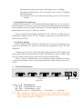
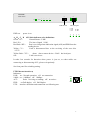
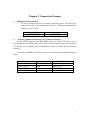
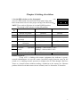
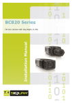
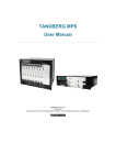
RC901-FE4E1 (version D)
Fast-Ethernet to 4 E1 links
Interface Converter
Manual
Beijing Raisecom Science & Technology Co. Ltd
Contents
Chapter 1 Overview
3
Chapter 2 Connection Features
6
Chapter 3 Guide of Installation
7
Chapter 4 Setting of switches
9
Chapter 5 Troubleshooting
13
2
Chapter 1 Overview
1.Description
RC901- FE4E1, 10/100M auto-sensing Ethernet interface converter of Ethernet
to 4E1, is one product of RC series converters made by Beijing Raisecom Science &
Technology Co. Ltd. It provides a simple solution to enable Ethernet access by using
4 E1 links for signal transmissions.
2. Specifications:
1) E1 Interface
Type: BNC (75 Ω, unbalanced)
RJ-45 (120 Ω, balanced)
Bit rate: 2048Kbps±50ppm
Line code: HDB3
Compliance: ITU-T G.703,
ITU-T G.823
Other features:
Real-time BER detecting and E1links auto protection auto-reset
Resistance for drift of 512UI, the ability of counteraction of jitter and drift
Selectable BER threshold of link auto-reset: 10-6 (default) or 10-5
2) Fast Ethernet Interface
Interface: RJ-45, cat5/cat5e cables available, supports link distance up to 100m
Bit rate: selectable, Auto-sensing 10M/100Mbps or manual configuration
Duplex type: Full/Half duplex auto-negotiation or manual configuration
Compliance: IEEE 802.3、IEEE 802.3u
Other features:
Supports maximum frame size up to 1536 bytes
Supports IEEE 802.3d Spanning Tree, 802.1q VLAN
Supports 1K MAC address table, address filtering, improve efficiency of
E1 link
Supports Auto-MDI/MIDX auto-negotiation
Supports Link Fault Pass-though (LFP)
Provides 64Mbit SDRAM for reducing the network congestion.
3. Features:
1) Forward features:
a: Store and Forward mode-----For normal data transmission, high resistance for
bursty.
b: Real-time Forward mode-------For higher requirement in real-time
transmission ability, for example, image transmission time can be reduced.
However, packet loss may occur.
3
Maximum forward speed in each E1 link supports up to 1920Kbps
Maximum forward speed for 4 E1 link supports up to 1920×4=7680Kbps
when fully loaded
The forward bit rate is auto allocated, depending on the real-time status of
E1 links.
2) Bandwidth auto-adjustment
RC901-FE4E1 supports 1~4 E1 link bandwidth auto-adjustment. If any of the E1
links disconnected, or when it is just back to normal from disconnecting, transmission
can be automatic achieved trough connecting E1 link and bandwidth can be adjusted
automatically, but at least 1 E1 link has to connect.
Every E1 link provides 2Mbps bandwidth. If 4 E1 links are working properly,
bandwidth is 8Mbps in total. E1 link “working” means the two converters have no
alarm occurs in E1 link.
3) Fault Pass Though
RC901-FE4E1 provides Fault Pass Though (FPT) for special requirements, e.g.
which need Spanning Tree, superior switch network management record. The FPT
defined as:
If alarm occur on all 4 E1 links, then all the links disconnect, FPT function will
suspend the UTP port and disconnect the links with Ethernet switches and NIC, until
any of E1 link no alarm occurred, then system is back to default status.
FPT set “close” as default status, it is convenient for those customers who have
no special requirements. Please see the manual about the switch setting of the panel if
need it.
4.
Panel and LED indicator
A
TX
BALANCE
B
RX
TX
BALANCE
C
RX
TX
BALANCE
4 E1 ports
Back panel
D
RX
TX
BALANCE
RX
Power
A、B、C、D 4 E1 link ports:
TX:BNC,75Ω unbalanced,output。
RX:BNC,75Ω unbalanced,input
BALANCE:RJ-45,120 Ω balanced,1、2 pin output,5、6 pin input
Note: BNC unbalanced interface cannot be used concurrently with RJ-45
balanced interface. The switches in bottom panel are used for setting the
type of cables. (Default is 75 Ω BNC).
4
Power switch
RAISECOM
RC901-FE4E1
SW
A
PWR
B
C
ETH
LNK
ACT
100M
FDX
D
LNK/LOS
DIP Switch
Ethernet port
G: LNK
R: LOS
Y: CUT
PWR :on
power is on.
A
B
RF: ERR
YF: RAL
C
D
A、B、C、D 4 E1 links indicator color definitions:
Green(G):
Normal Status(LNK)
Red(R):
The lost of signal(LOS)
Red flash(RF): Port is receiving alarm indication signal (AIS) and ERR from the
sending device.
Yellow(Y):
Link is disconnected due to the receiving of the error bits.
(CUT)
Yellow flash(YF):
alarm due to remote device(RAL)but local port.
Off:
Link is not in use
It takes few seconds for detection when power is just on, or when cables are
connecting or disconnecting of E1, please wait patiently.
See front panel for switching setting.
UTP Ethernet interface:
Indicators:
LNK: on,Normal operation;off,no connection。
100M: on,100Mbps;off,10Mbps。
ACT:
flash,receiving or sending;off,no action。
FDX: on Full duplex;off,Half duplex
UTP: interface definition and connection see following text.
LNK
100M
ACT
UTP
5
FDX
Chapter 2 Connection Features
1.
Equipment interconnection
1.
RC series interface converters are always working in pairs. They have to be
deployed in pairs as the models shown below. Otherwise abnormal data
transmission will occur.
Central Office
RC901/2-FE4E1
Customer
RC901-FE4E1
2.
Network equipment (Ethernet port) Connection features
RC901-FE4E1 supports auto MDI/MDIX crossover, when UTP port is set to
auto-negotiation. Switch and NIC can be connected by both direct line and cross line.
If UTP port is set to defined speed or Full-duplex mode, RC901-FE4E1 will lose this
function.
The feature of that RC901-FE4E1 connects with other network equipment shown
below.
Part Number
RC901-FE4E1
RC901-FE4E1
RC901-FE4E1
RC901-FE4E1
Host-site equipment
Switch
HUB
Router
Ethernet Card
RJ-45 connecting mode
MID CAT5
MID CAT5
MIDX CAT5
MIDX CAT5
6
Chapter 3 Guide of Installation
1.Make sure the E1-link cables are compatible with the RC901-FE4E1
If the E1 links with which you want to connect RC901-FE4E1 are combined
with PDH or SDH equipments, please check the interface type of E1, definition
and impedance of interface in relevant manuals.
2. Choose proper E1 link cables
Unbalanced: SYV 75-2-2 coax, up to 200m
Balanced:
0.6mm(22AWG) twisted pairs, up to 1500m
3.BALANCE-RJ45 UTP E1 pin defined as shown below
Refer to the table and figure below when use the balanced interface (120 Ω)
DIP No.
1
2
3
4
5
Label
TD+
TDGND
GND
RD+
Signification Output+ Output- Ground Ground Input+
6
7
8
RDGND
GND
Input- Ground Ground
120Ω balanced interface connect with other equipment, need specify the pin of
the equipment. The connection of UTP pin is shown below.
RC BALANCE-RJ45
TD+
TD-
RD+
RD-
GND
Note:
E1 balanced interface
Output +
OutputInput+
Input-
Ground
TD+ and TD- are always in one twisted pairs
RD+ and RD- are always in one twisted pairs
4.、Operation Environment:
Temperature:0-45℃
Humidity:
5%~90% non-condensing
5. Power supply requirements:AC/DC
AC:AC 220v/50Hz(range from165V to 265V)
DC:DC-48v(range from -36V to-72V)
Power consumption:≤ 5W
6. Dimensions:
440×43.6×180mm——standard 19’ 1U chassis mountable
7
7.
DC power supply installation guide。
DC power supply module provides 3 connectors: -48V, Ground, 0V, the
connection of ground is necessary to the safety.
-48V
GND
0V
8
Chapter 4 Setting of switches
OFF
1. Set the DIP switches on the front panel
A set of 6 DIP-switch is located on the front panel of the unit.
Refer to the table below for the proper setting of the DIP-switch.
ON
12345678
NOTE: The switch is ON when it is in the DOWN position.
The switch is OFF when it is in the UP position.
Switch
Function
OFF(default)
ON
No.
1
Remote loop-back
Disabled
Enabled
2
Local loop-back
Disabled
Enabled
-6
3
Bit
error
ratio
10
10-5
threshold
4
Version
REV.D
REV.A、REV.B
Selection
5
Preserving
Normal
Preserving
6
Ethernet
operation 100Mbps(when switch 5=ON)
mode
10Mbps(when switch 5=ON)
7
8
Fault Pass Though
Disable
Enable
Remote loop-back:
If any of E1 is linking with remote equipment (the indicator is green),
network administrator can run the remote loop-back testing function (turn on the
switch no.1), enabling network operators to diagnose the E1 links though a Bit Error
Tester at a central location without sending a technician to the remote site. Ethernet
packets of both Local and remote site are isolated, can’t be forward to E1 interface.
9
E link
Local
Ethernet
Converter
Remote
A link
A link
B link
B link
C link
C link
D link
D link
Converter
Ethernet
Error tester
Error tester
Error tester
Remote Loop-back Testing
Local loop-back:
Local loop-back testing makes both local E1 and Ethernet signal loop-back
outward, this function is designed for testing equipment interface. Connecting E1
BERT is for testing E1 interface; Sniffer is for diagnosing Ethernet interface. Note,
Ethernet data also loop-back during local loop-back, it easy to make broadcast storm
which occurred in Ethernet switches connected with local equipment. In case to avoid
broadcast storm, disconnect with switch before loop-back.
E1 link
A port
Sniffer
B port
E1 bit error tester
C port
D port
Local Loop-back Testing
Bit error ratio threshold
When the BER exceed the threshold, the yellow LED indicator is on, and auto
terminate transmission, then Ethernet packets will not be transmitted in this E1 link.
Until this link reconnecting, the green indicator is on, the transmission resumes.
Two thresholds are provided in RC901-FE4E1, 10-6 (as default) and 10-5.
Compatibility Selection:
In order to be compatible with previous version REV.A and REV.B, there is a version
switch in version d. When the version d interconnect with version A and B, the
version switch need to set to on, however, the new functions of c version are disabled,
10
such as remote loop-back etc.
Ethernet operation mode
The Ethernet port is default as auto-sensing and provides auto MDI/MDIX
crossover function. If need change the status of port, please refer to the table shown
below for setting.
Connecting
equipment (NIC,
switch etc.)
Setting of Ethernet port of converter
a. Enable auto-sensing (default) function, 100M full duplex
(common mode) will be obtained.
b. Disable auto-sensing function, force port to 10M half
10/100M
duplex mode. 10M half-duplex will be obtained.
Auto-sensing
c. Disable auto-sensing function, force port to 10M full duplex
port
mode. 10M full duplex will be obtained.
d. Disable auto-sensing, force port to 100M half duplex mode.
100M half-duplex will be obtained .
a. Disable auto-sensing function, force port to 10M half
10M
duplex. 10M half duplex will be obtained.
Half duplex port
Disable auto-sensing function, force port to 10M full duplex.
10M
Full duplex port 10M full duplex will be obtained.
a. Enable auto-sensing (default) function, 100M full duplex
10M
will be obtained.
Auto-sensing
port
a. Disable auto-sensing function, force port to 100M half
100M
duplex mode. 100M half-duplex will be obtained.
Half duplex port
a. ex-factory default function, 100M full duplex will be
100M
Full duplex port obtained.
a. Enable auto-sensing function (default), 100M half-duplex
100M
will be obtained.
Auto-sensing
b. Disable auto-sensing function, force port to 100M half
port
duplex mode. 100M half-duplex will be obtained.
See figures below for setting:
OFF
ON
OFF
ON
67
Ex-factory fault function
6 OFF
7 OFF
Forced 10M Half-duplex
6 ON
7 ON
OFF
ON
OFF
ON
Forced 10M Full-duplex
6 ON
7 OFF
Forced 100M half-duplex
6 OFF
7 ON
11
Fault pass though
RC901-FE4E1 provides Fault Pass Though (FPT) function for special
requirements.
In case of any E1 link was out of work, RC901-FE4E1 could transmit the
Ethernet packets in the other available E1 links automatically, until all E1 links were
not available.
And RC901-FE4E1supports IEEE 802.3d Spanning Tree.
2. Set the bottom panel switches
Four sets of DIP-switch located in the bottom panel are use to configure the
impedance and the type of the E1 connector.
E1 interface side
A
B
C
D
ON
OFF
1234
Bottom panel
ON
OFF
ON
OFF
E1 link connector:75 ohm, unbalanced,BNC
1234
E1 link connector:120 ohm,balanced, RJ-45
1234
Impedance and connector type in each E1 link can be set as the networks’
requirements
Flexile configurations in 4 Ethernet ports enable the interface
converter to meet various requirements in today dynamic networks.
12
Chapter 5 Troubleshooting
If you meet some problem during installing and employing, please deal with
them by the following proposals. If there is no answering for the question, please
contact with distributors for technical support.
1.PWR indicator is down
Answering: PWR line is not connected or there is any error in the PS system.
2.UTP LNK indicator is down
Answering: Please check the twisted pairs are good or damaged and the network
device that is connected to the interface converter is running well or not.
Please check connection type is matching or not: if you close auto-sensing and
auto-identifying function of twisted pairs cable MDI/MDIX, then please use MDI
type when connected to HUB or switch; please use MDIX type when connected to
router or networking card.
Please check the fault-pass function is Enable or Disable. If it is Enable, it can
make Ethernet port to close.
3.E1 line indicator alarm
If there is E1 line alarm, please find the fault reason according to explaining of
front panel indicator.
4.Test way of E1 line bit error
Configure remote loop-back and local loop-back through switch of front panel.
Please use loop-back function carefully. And avoid to bringing Ethernet broadcast
storm.
5.No alarm show, LNK is light, ACT indicator keep winking. But the connection is
not working.
Please check work status of Ethernet port and networking device matching or not,
according to switch of front panel.
6.Networking frame loss rate is very high
possible reasons:
The duplex mode is not matching of converter and Ethernet TX ports;
Cabling connection false;
E1 interface impedance type is not matching;
There is some frame loss, because the rate of Ping is beyond transmission rate of
E1. You can increase parameter of timeout.
13