1
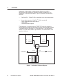
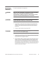
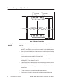
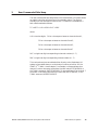
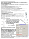
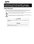
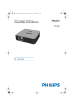
SIMATIC TI560/TI565 Redundant I/O System User Manual Order Number: PPX:560/565–8108–3 Manual Assembly Number: 2597773–0030 Third Edition Copyright 1993 by Siemens Industrial Automation, Inc. All Rights Reserved — Printed in USA Reproduction, transmission or use of this document or contents is not permitted without express consent of Siemens Industrial Automation, Inc. All rights, including rights created by patent grant or registration of a utility model or design, are reserved. Since Siemens Industrial Automation, Inc. does not possess full access to data concerning all of the uses and applications of customer’s products, we do not assume responsibility either for customer product design or for any infringements of patents or rights of others which may result from our assistance. Technical data is subject to change. We check the contents of every manual for accuracy at the time it is approved for printing; however, there may be undetected errors. Any errors found will be corrected in subsequent editions. Any suggestions for improvement are welcomed. MANUAL PUBLICATION HISTORY SIMATIC TI560/TI565 Redundant I/O System User Manual Order Manual Number: PPX:560/565–8108–3 Refer to this history in all correspondence and/or discussion about this manual. Event Date Description Original Issue Second Issue Third Issue 09/88 02/89 1/94 Original Issue (2601358–0001) Second Edition (2601358–0002) Third Edition (2601358–0003) LIST OF EFFECTIVE PAGES Pages Description Cover/Copyright History/Effective Pages 1 — 13 Registration Third Edition Third Edition Third Edition Third Edition Pages Description Redundant I/O System 1 2 3 Overview . . . . . . . . . . . . . . . . . . . . . . . . . . . . . . . . . . . . . . . . . . . . . . . . . . . . . . . . . . . . . . . . . . . . . . . 2 Communication between Units . . . . . . . . . . . . . . . . . . . . . . . . . . . . . . . . . . . . . . . . . . . . . Planning Redundant I/O Installation . . . . . . . . . . . . . . . . . . . . . . . . . . . . . . . . . . . . . . . . . Determining Signal Losses . . . . . . . . . . . . . . . . . . . . . . . . . . . . . . . . . . . . . . . . . . . . . . . . . . . 3 3 3 Hardware Components . . . . . . . . . . . . . . . . . . . . . . . . . . . . . . . . . . . . . . . . . . . . . . . . . . . . . . . . . 5 Software Requirements . . . . . . . . . . . . . . . . . . . . . . . . . . . . . . . . . . . . . . . . . . . . . . . . . . . . . Status Words . . . . . . . . . . . . . . . . . . . . . . . . . . . . . . . . . . . . . . . . . . . . . . . . . . . . . . . . . . . . . . . Remote Base Controller . . . . . . . . . . . . . . . . . . . . . . . . . . . . . . . . . . . . . . . . . . . . . . . . . . . . . LED Display . . . . . . . . . . . . . . . . . . . . . . . . . . . . . . . . . . . . . . . . . . . . . . . . . . . . . . . . . . . . . . . . . Setting the RBC Number . . . . . . . . . . . . . . . . . . . . . . . . . . . . . . . . . . . . . . . . . . . . . . . . . . . . Power Supply . . . . . . . . . . . . . . . . . . . . . . . . . . . . . . . . . . . . . . . . . . . . . . . . . . . . . . . . . . . . . . I/O Base and Adapter Chassis . . . . . . . . . . . . . . . . . . . . . . . . . . . . . . . . . . . . . . . . . . . . . . . RBC and Power Supply Installation and Removal . . . . . . . . . . . . . . . . . . . . . . . . . . . . . User-Supplied Materials . . . . . . . . . . . . . . . . . . . . . . . . . . . . . . . . . . . . . . . . . . . . . . . . . . . . . 5 5 6 8 8 9 9 11 12 User-Commanded Role Swap . . . . . . . . . . . . . . . . . . . . . . . . . . . . . . . . . . . . . . . . . . . . . . . . . . . 13 List of Figures 1 2 3 4 5 Redundant I/O System Diagram . . . . . . . . . . . . . . . . . . . . . . . . . . . . . . . . . . . . . . . . . . . . . Dual Tap-Splitter Arrangement for each I/O Channel . . . . . . . . . . . . . . . . . . . . . . . . . Remote Base Controller . . . . . . . . . . . . . . . . . . . . . . . . . . . . . . . . . . . . . . . . . . . . . . . . . . . . . Dimensions for PPX:500–9940 Adapter Chassis . . . . . . . . . . . . . . . . . . . . . . . . . . . . . . . . Power Connections . . . . . . . . . . . . . . . . . . . . . . . . . . . . . . . . . . . . . . . . . . . . . . . . . . . . . . . . . 2 4 7 10 12 List of Tables 1 2 3 Dual Tap Losses (dB) . . . . . . . . . . . . . . . . . . . . . . . . . . . . . . . . . . . . . . . . . . . . . . . . . . . . . . . . Status Words . . . . . . . . . . . . . . . . . . . . . . . . . . . . . . . . . . . . . . . . . . . . . . . . . . . . . . . . . . . . . . . LED Messages . . . . . . . . . . . . . . . . . . . . . . . . . . . . . . . . . . . . . . . . . . . . . . . . . . . . . . . . . . . . . . SIMATIC TI560/TI565 Redundant I/O System User Manual Redundant I/O System 4 6 8 1 1 Overview Redundant I/O provide for an enhanced Hot Backup Unit (HBU) configuration that extends the redundant hardware capabilities. The Redundant I/O system (illustrated in Figure 1) consists of the following elements. • Two SIMATIC TI560/TI565 controllers in an HBU configuration • One to eight channels of SIMATIC TI500 remote I/O • Dual remote base controllers (RBCs) • Dual cables • Dual base power supplies The Redundant I/O system uses the TI560/TI565 controller hardware unchanged and provides the same major functions as the standard system. It supports memory configuration, I/O configuration, TI500 operational modes, I/O cycles, Relay Ladder Logic execution, SF communication, and operator interfaces. HBU TI560/TI565 R C C TI560/TI565 R C C Channel 1 Channel 2 Channel 1 Channel 2 Dual Tap and Splitter Trunk A To other taps Trunk B Tap Base P P S* S* R B C Tap To other taps R B C * Power Supply Figure 1 Redundant I/O System Diagram 2 Redundant I/O System SIMATIC TI560/TI565 Redundant I/O System User Manual Communication between Units Standard CATV taps and splitters combine I/O channels from the remote channel controllers (RCCs) to form two separate trunks (redundant I/O). Each trunk leads to one of two RBCs located in an adapter chassis that also houses two power supplies. When the active RCC transmits, the dual tap and splitter arrangement splits the signal three ways: to the standby RCC, to Trunk A, and to Trunk B. When the active RBC transmits, the dual tap and splitter arrangement splits the transmitted signal from either Trunk A or Trunk B two ways: to the standby RCC and to the active RCC. Each redundant RCC, RBC, or power supply can detect internal operating faults. During normal operation, the RCC detects trunk faults and recognizes the appearance or disappearance of redundant RBCs and power supplies. When a fault is detected in the unit designated as active, the corresponding backup unit automatically assumes control with minimal process interruption and without operator intervention. All input, output, and SF message transactions occur between the active RCC and the active RBC. The active RCC directs configuration messages to both the active and standby RBCs, and the addressed RBC is responsible for acknowledging the message. A “status request” command goes to the active RBC to determine dual power supply status and to the standby RBC to determine the condition of the standby transmitters. If the standby does not respond to this request, the RCC directs the active RBC to command the standby to assume a failed state. When communication problems develop between the RCC and the active RBC, the RCC directs a “role swap” command to the standby RBC. Planning Redundant I/O Installation The SIMATIC TI560T/TI565T System Manual (PPX:560/565–8109–x) contains detailed instructions for installing remote I/O and for developing a power budget. The SIMATIC TI560/565 Hot Backup Installation Manual (PPX:560/565–8103–x) provides details about the additional signal losses with the Hot Backup Unit. Consult these manuals for installing the overall I/O system. Determining Signal Losses The installation of the Redundant I/O system requires dual cables and a dual tap/splitter arrangement as shown in Figure 2. In developing the power budget, you must include the dual tap and splitter losses. Table 1 lists typical losses obtained when using taps and splitters with the values shown. SIMATIC TI560/TI565 Redundant I/O System User Manual Redundant I/O System 3 Overview (continued) ! $& $' ! !$$" !$$" #"$ ## ! ## !$$" ## "% "% $!&%##"$ ## Figure 2 Dual Tap-Splitter Arrangement for each I/O Channel Table 1 Dual Tap Losses (dB) Active to standby 14.0 dB Active to trunk A 6.2 dB Active to trunk B 10.5 dB Standby to trunk A 10.5 dB Standby to trunk B 6.2 dB These losses are based on the following assumed values: Tap loss 7.0 dB Tap insertion loss 2.7 dB Splitter loss 3.5 dB The tap losses shown in Table 1 were obtained in the following manner. See Figure 2 for location of the different losses. For example, loss for Active to Standby is the sum of the two tap losses: 7.0 + 7.0 = 14.0. Active to Trunk A loss is the sum of the insertion loss and the splitter loss: 2.7 + 3.5 = 6.2. Active to Trunk B loss is the sum of the tap loss and the splitter loss: 7.0 + 3.5 = 10.5. 4 Redundant I/O System SIMATIC TI560/TI565 Redundant I/O System User Manual 2 Hardware Components The remote I/O for the Redundant I/O system consists of a Hot Backup installation, plus the following components for each redundant I/O base. ! WARNING Do not use either the PPX:500–2151 power supply or non-dual RBCs with a PPX:500–9940 adapter chassis in a redundant I/O configuration. To do so may cause improper operation of your system. • Two PPX:500–9912 Remote Base Controllers (RBCs) • Two PPX:500–2151A 110/220 VAC Power Supplies • PPX:500–5864, 8-Slot Base or PPX:500–5828, 16-Slot Base • PPX:500–9940 Redundant Controller Adapter Chassis • User-supplied cables, grounding materials, and taps Software Requirements The RCC, CPU, SFCPU, and HBU software must be Rel 2.1, or greater. With earlier software releases, a redundant I/O base with dual RBCs causes the RCC to fail that base. Either the dual RBC or dual Power Supply may be used in single mode operation with any RCC software releases. Non dual RBCs may be used with any RCC. Status Words Rel 2.1 includes additional status words to indicate the presence of Redundant I/O components. Status Words 168–175 indicate whether or not dual RBCs are present; status words 176–183 indicate the presence of dual power supplies. Table 2 lists the status words and shows the channel and base indicated by each word. If a “1” appears in a bit showing the status of a base containing dual RBCs, check the corresponding bit for that base in status words 2–9 to determine if the other RBC is still functioning. SIMATIC TI560/TI565 Redundant I/O System User Manual Redundant I/O System 5 Hardware Components (continued) Table 2 Status Words Status Words Indicating Dual RBCs Status Words Indicating Dual Power Supplies Word Bit* Base Channel Word Bit** Base Channel 168 16 | 1 0 | 15 1 176 16 | 1 0 | 15 1 169 16 | 1 0 | 15 2 177 16 | 1 0 | 15 2 170 16 | 1 0 | 15 3 178 16 | 1 0 | 15 3 171 16 | 1 0 | 15 4 179 16 | 1 0 | 15 4 172 16 | 1 0 | 15 5 180 16 | 1 0 | 15 5 173 16 | 1 0 | 15 6 181 16 | 1 0 | 15 6 174 16 | 1 0 | 15 7 182 16 | 1 0 | 15 7 175 16 | 1 0 | 15 8 183 16 | 1 0 | 15 8 *Bit = 0: Dual RBCs present and good Bit = 1: Error condition or single RBC ** Bit = 0: Dual power supply present and good Bit = 1: Error condition or single power supply Remote Base Controller 6 Each RBC (Figure 3) in the Redundant I/O system is an intelligent interface between an RCC and a remote base containing either 8 or 16 I/O slots. The dual RBCs are installed in an adapter chassis connected to the I/O base, which can be located up to 15,000 feet from the PLC. If both RBCs are installed and operational at power-up, the RBC on the right assumes the active role. Redundant I/O System SIMATIC TI560/TI565 Redundant I/O System User Manual # " # %" % #$ $ %$ " "$) """ #$) " #$ '$ $%$ #$) '" #%" #$$ $ # +*"%# "" $ #"$'$"' $# & &"$##$ &$ #"" % "$"" # #$ # ##%"" !% $ # !% $" #$ #$ #$ "%( '" #$ " ( "" $ #"$'$"' $# & Figure 3 Remote Base Controller SIMATIC TI560/TI565 Redundant I/O System User Manual Redundant I/O System 7 Hardware Components (continued) LED Display The LED at the top of each RBC displays a number to indicate RBC status or errors. The messages conveyed by the numbers are shown in Table 3. Table 3 LED Messages Number Meaning 0 RBC good –– configuration match 1 Self-diagnostics failure 2 Module mismatch 3 Communications time-out 4 RAM parity error 5 Standby unit, not configured 6 Standby good, wrong address 7 Communications good, but no I/O configured 8 Watchdog time-out C Standby unit, configured NOTE: If an RBC is configured in the PLC (LED display 0) and you delete it from PLC memory, the LED display does not change (LED display 7) until a restart or power cycle is performed. To reset an RBC with a 1 displayed, move the base address thumbwheel switch to another address for 0.5 seconds, then return the switch to the correct address. The RBC will attempt to come on-line. Setting the RBC Number 8 The top thumbwheel switch on the face of each RBC allows you to select the RBC number (0–15) on the RCC channel. RBC numbers must not be duplicated on another base; however, the active and standby RBCs on the redundant base must have the same number. Redundant I/O System SIMATIC TI560/TI565 Redundant I/O System User Manual Power Supply The Redundant I/O system uses two PPX: 500–2151A, 110/220 VAC power supplies that are installed in the adapter chassis, along with the RBCs. During normal operation, both power supplies are active. These units convert user-supplied power (either 110 or 220 VAC) to DC power. Each power supply module is protected from internal short circuits by a 3 A, 250 VAC slow-blow fuse. The internal circuitry maintains two DC voltages at –5 V and +5 V. On each module, the indicator labeled “DC GOOD” is on when the module is producing the correct DC power. The indicator is off when overvoltage, undervoltage, or overcurrent faults are detected. NOTE: To allow replacement of a unit without taking down the entire base, AC power to each power supply must come from separate sources with the commons at the same potential, and you must provide a means of disconnecting AC power from each power supply. I/O Base and Adapter Chassis To install the dual RBCs and power supplies, use either the PPX:500–5864, 8-Slot Base or the PPX:500–5828, 16-Slot Base with the PPX:500–9940 Redundant Controller Adapter Chassis. The adapter chassis attaches to the right side of the I/O base and provides slots for the two power supplies and the two RBCs. In planning the installation of the I/O bases for the Redundant I/O system, follow the guidelines in the manual that comes with the bases. To mount the PPX:500–9940 Adapter Chassis, see Figure 4 for template dimensions, and follow these steps. 1. When preparing the mounting panel, be certain the base and adapter are positioned for proper contact of the connectors. 2. Partially insert the two top screws in the panel. 3. Fit the screws into the holes in the adapter base (see Figure 4). Slide the assembly down and to the left until the screws support the adapter chassis and the base connectors are fully seated. 4. Attach the lower portion of the assembly to the panel with two #10 screws. 5. Tighten all screws. SIMATIC TI560/TI565 Redundant I/O System User Manual Redundant I/O System 9 Hardware Components (continued) Figure 4 Dimensions for the PPX:500–9940 Adapter Chassis 10 Redundant I/O System SIMATIC TI560/TI565 Redundant I/O System User Manual RBC and Power Supply Installation and Removal To install the Redundant I/O components: ! WARNING When you install Redundant I/O components or when you need to replace a unit, ensure that the installation location is non-hazardous; i.e. before you insert or remove an RBC or power supply, be certain that flammable gases are not present. ! WARNING In order to prevent disruption of the I/O channel, disconnect the coaxial cable before removing or installing an RBC. ! WARNING 1. Plug an RBC into each of the two connectors at the right side of the adapter chassis and tighten the top and bottom screws on each unit. The RBC in the right slot assumes the active role when the base is powered up. 2. Connect a coaxial cable to the top of each RBC. Before removing or installing a power supply, disconnect the AC power to the slot for that power supply. 3. Plug the power supplies into the two slots on the left side of the adapter chassis. Be certain the module is fully seated and that the tabs at the top and bottom have snapped into place. 4. After the power supply is inserted, attach the AC and ground wires as shown in Figure 5. To reduce the probability of failure, power to each module should come from different sources with the commons at the same potential. Use the voltage selector on the PPX:500–2151A to set the input power for either 110 or 220 VAC. (See the PPX:500–2151 and PPX:500–2151A 110/220 VAC Power Supply Installation Manual for details on setting input voltage.) SIMATIC TI560/TI565 Redundant I/O System User Manual Redundant I/O System 11 Hardware Components (continued) AC Hot AC Hot Chassis GND Chassis GND AC Common AC Common I/O Base Power Supply Power Supply R R B B C C Figure 5 Power Connections User-Supplied Materials 12 To install the Redundant I/O system, you need the following additional materials: • CATV grounding blocks or bulkhead coaxial connectors to install at each RCC and RBC to shunt noise on the coaxial cable shield to ground • Semi-rigid coaxial cable (two sizes) to use for trunk line(s) and for drop lines • CATV taps to insert in the trunk distribution cable to provide drops from the active and standby PLCs to the RBCs • Taps and splitters to distribute the signal from the active RCC to the standby RCC, Trunk A, and Trunk B • Taps and splitters to distribute the signal from the active RBC (either Trunk A or B) to the standby RCC and the active RCC • Semi-rigid coaxial cable fittings to connect trunk distribution cable to tap housing • F-type connectors to connect drop cable to tap housing • Terminators to install on all unused terminals on a multi-drop tap Redundant I/O System SIMATIC TI560/TI565 Redundant I/O System User Manual 3 User-Commanded Role Swap The user-commanded role swap feature of the Redundant I/O system allows an orderly transition of the active unit to standby status. The original standby unit then assumes the active role. This feature is accessed via a task code formatted as follows: TC = 43FE + LAR + 0310 + RCC + RBC where LAR = two hex digits, F0 for role swaps on bases on channels 0 and 1, F2 for role swaps on bases on channels 2 and 3, F4 for role swaps on bases on channels 4 and 5, F6 for role swaps on bases on channels 6 and 7 RCC = single hex digit corresponding to channel number (0 – 7) RBC = single hex digit corresponding to base number (0 – F) This task code may be transmitted either directly to the Redundant I/O system as formatted above, or as the body of a native primitive “01” to a SIMATIC TIWAY Host Adapter. For example, to command base 0 on channel 1 to do a role swap, send either the task code, 43FEF0031010, or the TIWAY command, 0143FEF0031010. To command base 15 on channel 7 to conduct a role swap, send either the task code, 43FEF603107F, or the TIWAY command, 0143FEF603107F. SIMATIC TI560/TI565 Redundant I/O System User Manual Redundant I/O System 13 Customer Registration We would like to know what you think about our user manuals so that we can serve you better. How would you rate the quality of our manuals? Excellent Good Fair Poor Accuracy Organization Clarity Completeness Overall design Size Index Would you be interested in giving us more detailed comments about our manuals? Yes! Please send me a questionnaire. No. Thanks anyway. Your Name: Title: Telephone Number: ( ) Company Name: Company Address: Manual Name: SIMATIC TI560/TI565 Redundant I/O System User Manual Manual Assembly Number: 2597773–0030 Order Number: PPX:560/565–8108–3 Edition: Date: Third 1/94 FOLD NO POSTAGE NECESSARY IF MAILED IN THE UNITED STATES BUSINESS REPLY MAIL FIRST CLASS PERMIT NO.3 JOHNSON CITY, TN POSTAGE WILL BE PAID BY ADDRESSEE ATTN: Technical Communications M/S 3519 SIEMENS INDUSTRIAL AUTOMATION INC. 3000 BILL GARLAND RD P O BOX 1255 JOHNSON CITY TN 37605–1255 FOLD