1
Library Reference
4
4.2.2
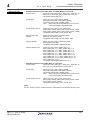
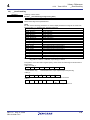
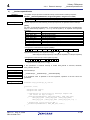
Return value
Timer MTU2
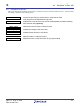
If the specification of timer is invalid, RAPI_FALSE is returned; otherwise, RAPI_TRUE is
returned.
Category
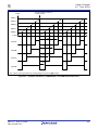
Timer MTU2 (pulse period measurement mode)
Reference
__CreateInputCapture
Remark
__CreatePulsePeriodMeasurementMode
If an undefined value is specified in the first argument, operation of the API cannot be
guaranteed.
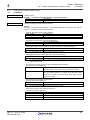
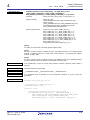
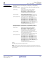
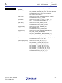
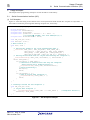
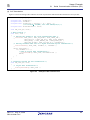
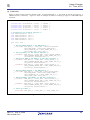
Program example
#include "rapi_timer_sh_7125.h"
/* Declaration of callback function */
void TimerIntFunc( void );
void func( void )
{
/* Setting MTU2 channel 4 for pulse period measurement mode */
__CreatePulsePeriodMeasurementMode( RAPI_MTU2_4 | RAPI_MP_4 |
RAIP_RISING_EDGE | RAPI_TCNT_CLEAR_DIS | RAPI_OVERFLOW_ENA |
RAPI_TIMER_INT_LV_1, TimerIntFunc );
}
Rev.1.01 Aug. 27, 2008
REJ10J1906-0101
4-56