1
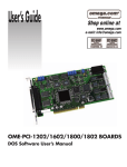
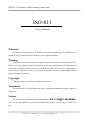
ISO813 32-channels isolated analog input card
ISO-813
User’s Manual
Warranty
All products manufactured by ICP DAS are warranted against defective materials for a
period of one year from the date of delivery to the original purchaser.
Warning
ICP DAS assume no liability for damages consequent to the use of this product. ICP
DAS reserves the right to change this manual at any time without notice. The information
furnished by ICP DAS is believed to be accurate and reliable. However, no responsibility is
assumed by ICP DAS for its use, nor for any infringements of patents or other rights of third
parties resulting from its use.
Copyright
Copyright 1998 by ICP DAS. All rights are reserved.
Trademark
The names used for identification only may be registered trademarks of their respective
companies.
License
The user can use, modify and backup this software
on a single machine.
The user may not reproduce, transfer or distribute this software, or any copy, in whole or in
part.
ISO-813 User’s Manual (Ver.1.2, Oct/2003, IPH-011-12)
----1
ISO813 32-channels isolated analog input card
Tables of Contents
1. INTRODUCTION ..........................................................................................4
1.1. GENERAL DESCRIPTION ................................................................................................4
1.2. FEATURES .......................................................................................................................4
1.3. SPECIFICATIONS ..............................................................................................................5
1.3.1. Power Consumption :......................................................................................................................... 5
1.3.2. Analog Inputs ..................................................................................................................................... 5
1.3.3. A/D Converter .................................................................................................................................... 5
1.3.4. Applications ....................................................................................................................................... 6
1.4. PRODUCT CHECK LIST .....................................................................................................6
2. HARDWARE CONFIGURATION..............................................................7
2.1. BOARD LAYOUT ..............................................................................................................7
2.2. I/O BASE ADDRESS SETTING ...........................................................................................8
2.3. JUMPER SETTING .............................................................................................................9
2.3.1. JP1 : Analog Input Range Selection .................................................................................................. 9
2.3.2. JP2 : Bipolar / Unipolar Selection..................................................................................................... 9
2.4. I/O REGISTER ADDRESS ................................................................................................10
2.4.1. A/D Input Buffer Register................................................................................................................. 11
2.4.2. A/D Gain Control Register............................................................................................................... 12
2.4.3. A/D Multiplex Control Register ....................................................................................................... 13
2.4.4. A/D Software Trigger Control Register ........................................................................................... 14
2.4.5. A/D Conversion................................................................................................................................ 15
3. CN1 PIN ASSIGNMENT ............................................................................16
3.1. DAUGHTER BOARD ( OPTION ) ......................................................................................17
3.1.1. DB-8325 Screw Terminal Board...................................................................................................... 17
3.1.2. DB-37/ DN-37 general purpose screwing terminal board............................................................... 17
4. SOFTWARE .................................................................................................18
4.1.COMPILER & LINK ..........................................................................................................19
4.1.1. using MSC ....................................................................................................................................... 19
4.1.2. using TC ........................................................................................................................................... 19
4.1.2. using BC........................................................................................................................................... 19
4.2. C LANGUAGE LIBRARY .................................................................................................20
4.3. LIBRARY FUNCTIONS .....................................................................................................21
4.3.1. ISO813_Initialize ............................................................................................................................. 21
4.3.2 ISO813_ActiveBoard ........................................................................................................................ 22
ISO-813 User’s Manual (Ver.1.2, Oct/2003, IPH-011-12)
----2
ISO813 32-channels isolated analog input card
4.4. ISO813_CHECK_ADDRESS ...........................................................................................23
4.5. ISO813_AD_SETCHGAIN ............................................................................................24
4.6. ISO813_AD_POLLINGVAR...........................................................................................25
4.7. ISO813_AD_POLLINGARRAY ......................................................................................26
5. CALIBRATION ...........................................................................................27
5.1. CALIBRATION VR DESCRIPTION ....................................................................................27
5.1.1. Calibration Step ............................................................................................................................... 28
ISO-813 User’s Manual (Ver.1.2, Oct/2003, IPH-011-12)
----3
ISO813 32-channels isolated analog input card
1.
1.1.
Introduction
General
Description
The ISO-813 is a bus type isolated 12-bit 32-channel analog input board for the PC/AT
compatible computer. It’s isolatation range is increased to 3000V and extend the application
field to real industry application . It is backward compatible to ACL-813 add X16
programmable gain control range.
1.2.
Features
12-bit A/D resolution
3,000Vdc photo-isolation protection
The maximum sample rate of A/D converter is about 10K sample/sec
PC/AT compatible ISA bus
A/D trigger mode : software trigger
A/D data transfer mode : polling
32 single-ended analog inputs
Software selectable input ranges
Programmable gain : x1,x2,x4,x8,x16
Input range(Bipolar mode) : ±10V, ±5V,±2.5V,±1.25V,±0.625V, ±0.3125V
Input range(Unipolar mode):0~10V,0~5V,0~2.5V,0~1.25V,0~ 0.625V
Bipolar / Unipolar input mode by jumper selection
ISO-813 User’s Manual (Ver.1.2, Oct/2003, IPH-011-12)
----4
ISO813 32-channels isolated analog input card
1.3.
1.3.1.
Specifications
Power Consumption :
single power +5V @300 mA maximum
Operating temperature : 0°C ~50°C
1.3.2.
Analog Inputs
Channels : 32 single-ended , 12-bit resolution
isolation 3000Vdc
Input range : (software programmable)
Bipolar
:±10V ±5V, ±2.5V, ±1.25V, ±0.625V, ±0.3125V
Unipolar
: 0~10V,0~5V,0~2.5V,0~1.25V,0~0.625V
Input current : 250 nA max (125 nA typical ) at 25 °C.
On chip sample and hold
Over voltage : continuous single channel to 70Vp-p
Input impedance : > 10MΩ
1.3.3.
A/D Converter
Type : successive approximation , Burr Brown ADS-774 or equirement
Conversion time : 8 micro second.
Accuracy : +/- 1 bit
Resolution : 12 bits
ISO-813 User’s Manual (Ver.1.2, Oct/2003, IPH-011-12)
----5
ISO813 32-channels isolated analog input card
1.3.4. Applications
Signal analysis
FFT & frequency analysis
Transient analysis
Production test
Process control
Vibration analysis
Energy management
Industrial and lab. measurement and control
1.4.
Product Check List
In addition to this manual, the package includes the following items:
ISO-813 multifunction card
ISO-813 utility diskette
Attention !
If any of these items is missing or damaged, contact the dealer who
provides you this product. Save the shipping materials and carton in
case you want to ship or store the product in the future.
ISO-813 User’s Manual (Ver.1.2, Oct/2003, IPH-011-12)
----6
ISO813 32-channels isolated analog input card
2.
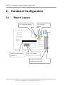
2.1.
Hardware Configuration
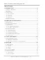
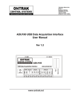
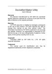
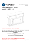
Board Layout
JP1: Input range setting
3000Vdc photo-isolation
protection
JP2: Unipolar /
Bipolar
SW1 : I/O Address
37-pin D-sub connector
32 channels analog input
ISO-813 User’s Manual (Ver.1.2, Oct/2003, IPH-011-12)
----7
ISO813 32-channels isolated analog input card
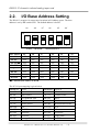
2.2.
I/O Base Address Setting
The ISO-813 occupies 16 consecutive locations in I/O address space. The base
address is set by DIP switch SW1. The default address is 0x220.
A9
A8
A7
A6
A5
A4`
1
2
3
4
5
6
ON
SW1 : BASE ADDRESS
Base Adders
A9
A8
A7
A6
A5
A4
200-20F
OFF
ON
ON
ON
ON
ON
210-21F
OFF
ON
ON
ON
ON
OFF
220-22F( )
OFF
ON
ON
ON
OFF
ON
230-23F
OFF
ON
ON
ON
OFF
OFF
:
:
:
:
:
:
:
300-30F
OFF
OFF
ON
ON
ON
ON
:
:
:
:
:
:
:
3F0-3FF
OFF
OFF
OFF
OFF
OFF
( ) : default base address is 0x220
The PC I/O port mapping is given below.
ADDRESS
Device
ADDRESS DEVICE
000-1FF
PC reserved
320-32F
XT Hard Disk
200-20F
Game/control
378-37F
Parallel Printer
210-21F
XT Expansion Unit
380-38F
SDLC
238-23F
Bus Mouse/Alt. Bus Mouse 3A0-3AF
SDLC
278-27F
Parallel Printer
3B0-3BF
MDA/Parallel Printer
2B0-2DF
EGA
3C0-3CF
EGA
2E0-2E7
AT GPIB
3D0-3DF
CGA
2E8-2EF
Serial Port
3E8-3EF
Serial Port
2F8-2FF
Serial Port
3F0-3F7
Floppy Disk
300-31F
Prototype Card
3F8-3FF
Serial Port
ISO-813 User’s Manual (Ver.1.2, Oct/2003, IPH-011-12)
----8
ISO813 32-channels isolated analog input card
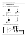
2.3.
Jumper Setting
2.3.1. JP1 : Analog Input Range Selection
10V
10V
20V
Input Range :+/-5V
Gain=1
Default setting
2.3.2.
20V
Input Range :+/-10V
Gain=1
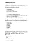
JP2 : Bipolar / Unipolar Selection
UNI
UNI
BI
Bipolar mode
Default setting
BI
Unipolar mode
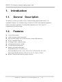
The input range will be change if the JP1 and JP2 in different position.
JP2
Unipolar
Reference
MUX.
32CH. A/I
Bipolar
Reference
PGA
Amp
JP1
10V
A/D Converter
20V
ISO-813 User’s Manual (Ver.1.2, Oct/2003, IPH-011-12)
----9
ISO813 32-channels isolated analog input card
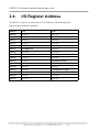
2.4.
I/O Register Address
The ISO-813 occupies 16 consecutive PC I/O addresses. The following table
lists the registers and their locations.
Address
Read
Write
Base+0
Reserved
Reserved
Base+1
Reserved
Reserved
Base+2
Reserved
Reserved
Base+3
Reserved
Reserved
Base+4
A/D Low Byte
Reserved
Base+5
A/D High Byte
Reserved
Base+6
Reserved
Reserved
Base+7
Reserved
Reserved
Base+8
Reserved
Reserved
Base+9
Reserved
A/D Gain Control
Base+A
Reserved
A/D Multiplexer Control
Base+B
Reserved
Reserved
Base+C
Reserved
A/D Software Trigger
Base+D
Reserved
Reserved
Base+E
Reserved
Reserved
Base+F
Reserved
Reserved
ISO-813 User’s Manual (Ver.1.2, Oct/2003, IPH-011-12)
----10
ISO813 32-channels isolated analog input card
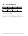
2.4.1.
A/D Input Buffer Register
(READ) Base+4 : A/D Low Byte Data Format
Bit 7
Bit 6
Bit 5
Bit 4
Bit 3
Bit 2
Bit 1
Bit 0
D7
D6
D5
D4
D3
D2
D1
D0
(READ) Base+5 : A/D High Byte Data Format
Bit 7
Bit 6
Bit 5
Bit 4
Bit 3
Bit 2
Bit 1
Bit 0
X
X
X
READY
D11
D10
D9
D8
X: Don’t Care
A/D 12 bits data : D11…..D0, D11=MSB, D0=LSB
READY =1 : A/D 12 bits data not ready
=0 : A/D 12 bits data is ready
The low 8 bits A/D data are stored in address BASE+4 and the high 4 bits data are stored in
address BASE+5. The READY bit is used as a indicator for A/D conversion. When a A/D
conversion is completed, the READY bit will be clear to zero.
ISO-813 User’s Manual (Ver.1.2, Oct/2003, IPH-011-12)
----11
ISO813 32-channels isolated analog input card
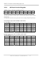
2.4.2.
A/D Gain Control Register
(WRITE) Base+9 : A/D Gain Control Register Format
Bit 7
Bit 6
Bit 5
Bit 4
Bit 3
Bit 2
Bit 1
Bit 0
X
X
X
X
X
GAIN2
GAIN1
GAIN0
X : Don’t Care
The gain control register control the gain of A/D input signal. Bipolar/Unipolar will effect
the gain factor.
It is important to select the correct gain-control-code according to Bipolar/Unipolar input
ISO-813 Bipolar mode GAIN CONTROL CODE TABLE
JP2 : Bipolar
GAIN
JP1 : 10V
JP1 : 20V
Input Range
Input Range
GAIN2
GAIN1
GAIN0
Hex
1
± 5V
± 10V
0
0
0
0x0
2
± 2.5V
± 5V
0
0
1
0x1
4
± 1.25V
± 2.5V
0
1
0
0x2
8
± 0.625V
± 1.25V
0
1
1
0x3
16
±0.3125
± 0.625
1
0
0
0x4
ISO-813 Unipolar mode GAIN CONTROL CODE TABLE
JP2 : Unipolar
GAIN
JP1 : 10V
JP1 : 20V
Input Range
Input Range
GAIN2
GAIN1
GAIN0
Hex
1
0~10V
Not use
0
0
0
0x0
2
0~5V
0~10V
0
0
1
0x1
4
0~2.5V
0~5V
0
1
0
0x2
8
0~1.25V
0~2.5V
0
1
1
0x3
16
0~0.625V
0~1.25V
1
0
0
0x4
ISO-813 User’s Manual (Ver.1.2, Oct/2003, IPH-011-12)
----12
ISO813 32-channels isolated analog input card
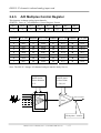
2.4.3.
A/D Multiplex Control Register
This function is change analog input channels.
(WRITE) Base+A : A/D Multilexer Control Register Format
Bit 7
Bit 6
Bit 5
Bit 4
Bit 3
Bit 2
Bit 1
Bit 0
X
X
X
D4
D3
D2
D1
D0
A/D input channel selection data = 5 bits : D4..D0, D4=MSB, D0=LSB, X=don‘t care
Channels MUX. data Channels MUX. Data Channels MUX. data Channels MUX. Data
0
0x00
8
0x08
16
0x10
24
0x18
1
0x01
9
0x09
17
0x11
25
0x19
2
0x02
10
0x0A
18
0x12
26
0x1A
3
0x03
11
0x0B
19
0x13
27
0x1B
4
0x04
12
0x0C
20
0x14
28
0x1C
5
0x05
13
0x0D
21
0x15
29
0x1D
6
0x06
14
0x0E
22
0x16
30
0x1E
7
0x07
15
0x0F
23
0x17
31
0x1F
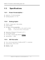
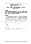
Note: The ISO-813 change A/I channnel and gain must be delay 10u sec.
BASE+0x0A
Select channels
0~31
BASE+0x09
Select Gains
1,2,4,8,16
Mux.
To A/D converter
Amp.
Delay time : 10uSec
ISO-813 User’s Manual (Ver.1.2, Oct/2003, IPH-011-12)
----13
ISO813 32-channels isolated analog input card
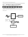
2.4.4.
A/D Software Trigger Control Register
(WRITE) Base+C : A/D Software Trigger Control Register Format
Bit 7
Bit 6
Bit 5
Bit 4
Bit 3
Bit 2
Bit 1
Bit 0
X
X
X
X
X
X
X
X
X=dont care, XXXXXXXX=any 8 bits data is validate
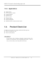
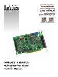
The ISO-813 A/D convertion is polling mode, The A/D converter must be trigger when you
reading each data.
Analog Signal
ADS-774
A/D converter
I/O BASE+0x0C
Software Trigger
Settling time
70u sec
PC 357
Photo-couple
12 Bits Digital Data
ISO-813 User’s Manual (Ver.1.2, Oct/2003, IPH-011-12)
----14
ISO813 32-channels isolated analog input card
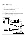
2.4.5.
A/D Conversion
This section explains how to get data from the A/D conversions and using
I/O register. Before use the A/D conversion function, user should notice the
following issue:
1.
2.
3.
4.
5.
6.
Makesure input range : Unipolar / Bipolar by JP2 , 10V / 20V by JP1 and gain value by
software setting from I/O BASE ADDRESS + 0x9
Select input channels : I/O BASE ADDRESS + 0xA (Channel 0~Channel 31)
Delay 10u sec
Trigger A/D Converter : I/O BASE ADDRESS + 0xC
Delay 70u sec
Get A/D MSB Data : I/O BASE ADDRESS + 0x5 and maksure A/D conversion ready
bit is logic low (Bits 4). ( Reading again if bit 4 is logic high )
Get A/D LSB Data : I/O BASE ADDRESS + 0x4
Conversion A/D data value : Ad_data=LSB x 256 + LSB
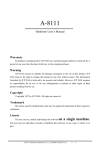
The block diagram is given below:
Analog
Input
32 channel
A/I input
BASE+0x9 : Gain
AMP.
JP2
UNI/
BI
JP1
10V/
20V
ADS-774
A/D Converter
12 Bits Data
BASE+0xC: A/D Trigger
3000Vdc Protection
Phtocouple
Bus-isolation
BASE+0xA: MUX
FPGA
SW1:I/O Address
Bas+0x5: MSB
Buffers
BASE+0x4: LSB
I/O Register
ISA DATA BUS
ISO-813 User’s Manual (Ver.1.2, Oct/2003, IPH-011-12)
----15
ISO813 32-channels isolated analog input card
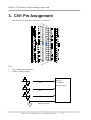
3. CN1 Pin Assignment
The ISO-813 provides three connectors. Connector 1,
Note:
1. AI_n: Analog input channel n
2. AGND : Analog Ground
AI_0
ISO-813
32 channel
Analog input
AI_1
AI_n
Analog Ground
ISO-813 User’s Manual (Ver.1.2, Oct/2003, IPH-011-12)
----16
ISO813 32-channels isolated analog input card
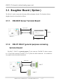
3.1. Daughter Board ( Option )
The ISO-813 can be connected with many different daughter boards. The function of these
daughter boards are described as follows.
3.1.1.
DB-8325 Screw Terminal Board
37pin cable
100/200mm
114mm
ISO-813
220mm
3.1.2.
DB-37/ DN-37 general purpose screwing
terminal board
The DB-37 / DN-37is a general purpose 37-pin connector. The DB-37is direct connect
to a 37-pin D-sub connector, the DN-37 via 37-pin d-sub cable connection . It is suitable for
easy signal connection and measurement.
37pin cable
100/200mm
DN-37
ISO-813
DB-37
ISO-813 User’s Manual (Ver.1.2, Oct/2003, IPH-011-12)
----17
ISO813 32-channels isolated analog input card
4. Software
The ISO813.lib is a collection of data acquisition subroutines for ISO-813. These
subroutines are written with C language and perform a variety of data acquisition operations.
These subroutines can be classified as follow:
It is recommended to install the ISO-813 application software to your hard disk to get
the best performance. Before beginning, to make a backup copy of the ISO-813 application
software. Store the original diskette in a safe place. The ISO-813 application disk includes
the following files:
DIAG\SETUP.EXE
: Diagnostic program for
ISO813\lib\ISO813S.lib
ISO813\lib\ISO813M.lib
ISO813\lib\ISO813C.lib
ISO813\lib\ISO813L.lib
ISO813\lib\ISO813H.lib
MS-WINDOWS 95
MS-WINDOWS 98
MS-WINDOWS NT 4.0
MS-WINDOWS 2000
: The small mode library for MSC/TC.
: The medium mode library for MSC/TC.
: The compact mode library for MSC/TC.
: The large mode library for MSC/TC.
: The huge mode library for MSC/TC.
ISO813\demo\*.*
: The demo program
ISO-813 User’s Manual (Ver.1.2, Oct/2003, IPH-011-12)
----18
ISO813 32-channels isolated analog input card
4.1. Compiler & link
4.1.1. using MSC
The including file is ISO813.H
There are 5 different mode library files : ISO813S/C/M/L/H.LIB
Support MSC 6.x compiler
SMALL mode compiler & link command :
CL /AS program.c ISO813S.LIB
COMPACT mode compiler & link command : CL /AC program.c ISO813C.LIB
MEDIUM mode compiler & link command :
CL /AM program.c ISO813M.LIB
LARGE mode compiler & link command :
CL /AL program.c ISO813L.LIB
HUGE mode compiler & link command :
CL /AH program.c ISO813H.LIB
A:\ISO813\demo\msc\*.bat give some examples for compiler&link batch file
4.1.2.
using TC
The including file is ISO813.H
There are 5 different model library files : ISO813S/C/M/L/H.LIB
Support TC 2.x compiler
Use text editor to create a project file include : program.c ISO813?.lib
Use TC integrated environment to select the correct compiler model
A:\ISO813\demo\*.prj give some examples for compiler&link project file
4.1.3.
using BC
The including file is ISO813.H
There are 5 different model library files : ISO813S/C/M/L/H.LIB
Support BC 3.x compiler
Use BC integrated environment to create a project file include : program.c ISO813?.lib
Use BC integrated environment to select the correct compiler model
A:\ISO813\demo\*.prj give some examples for compiler&link project file
ISO-813 User’s Manual (Ver.1.2, Oct/2003, IPH-011-12)
----19
ISO813 32-channels isolated analog input card
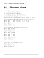
4.2.
C Language Library
ISO813.H
//********* Declare ISO813 Board Interface **************
int ISO813_ActiveBoard(int BoardNo);
int ISO813_Check_Address(int BaseAddr);
int ISO813_Initialize(int CardNo, int BaseAddr);
void ISO813_AD_SetChGain(int Channel , int Gain);
unsigned int ISO813_AD_PollingVar(void);
void ISO813_AD_PollingArray(unsigned int *Buffer, unsigned int Length);
/************ define ISO813 relative address **********************/
#define AD_LO
0x04
//Analog to Digital, Low Byte
#define AD_HI
0x05
//Analog to Digital, Hiht Byte
#define SET_GAIN 0x09
#define SET_CH
0x0A
#define SOFT_TRIG
0x0C
/************ define the gain mode *****************/
#define ISO813_BI_1 0x00
#define ISO813_BI_2 0x01
#define ISO813_BI_4 0x02
#define ISO813_BI_8 0x03
#define ISO813_BI_16 0x04
#define
#define
#define
#define
#define
ISO813_UNI_1 0x00
ISO813_UNI_2 0x01
ISO813_UNI_4 0x02
ISO813_UNI_8 0x03
ISO813_UNI_16
0x04
/******
#define
#define
#define
#define
define the error number *********/
NoError 0
CheckBoardError 1
TimeOutError 0xffff
CardNumError 4
ISO-813 User’s Manual (Ver.1.2, Oct/2003, IPH-011-12)
----20
ISO813 32-channels isolated analog input card
4.3. Library Functions
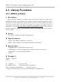
4.3.1. ISO813_Initialize
Description :
ISO813_Initialize initialize the ISO813 board. This function should be called before
using the other ISO813.lib subroutines. This function will detect automatically ISO813 board
according to I/O base address. Auto detection failure will occur if I/O base address not match
with hardware DIP switch. The others can perform A/D operation via polling. After this
subroutine is executed, the board which CardNo specified will be active. If more than one
board in a system, the ISO813_ActiveBoard(int CardNo, int BaseAddr) must use to switch to
the active board.
Syntax :
int
ISO813_Initialize(int CradNo, int BaseAddr );
Input Parameter :
CardNo : The validate card number is from 0 to 7.
IOBase : I/O base address. (must match with hardware DIP switch)
Return Value :
CheckBoardError : IO base address detection error
CardNumError : error in card number input (validate numbers are from 0 to 7)
CheckIrqError : error in IRQ channel number
NoError
Example 1 :
#include "ISO813.h"
main()
{
int CradNo=0;
/* only one card */
int IOBase=0x220;
/* The IO base address for ISO813 */
ISO813_Initialize(CardNo,IOBase);
/* board_0 is active */
/* only one card in this system, so no need to call ISO813_ActiveBoard(0) */
ISO-813 User’s Manual (Ver.1.2, Oct/2003, IPH-011-12)
----21
ISO813 32-channels isolated analog input card
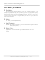
4.3.2. ISO813_ActiveBoard
Description :
This driver support 8 different cards in one system max. The ISO813_Initialize(…) will
initialize the separate boards. But only one board can be active at one time. So the software
should active the selected card before perform specific function. The ISO813_ActiveCrad(?)
is used to active the desired card in the system. If only one card in the system, there is no
need to use this subroutine.
Syntax :
int ISO813_ActiveBoard(int BoardNo);
Input Parameter :
BoardNo : The validate board number is from 0 to 7. This number is equal to CardNo in
ISO813_Initial(CardNo,…..);
Return Value :
CardNumError : error in card number input (validate numbersare from 0 to 7)
NoError
ISO-813 User’s Manual (Ver.1.2, Oct/2003, IPH-011-12)
----22
ISO813 32-channels isolated analog input card
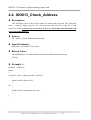
4.4. ISO813_Check_Address
Description :
This subroutine check if the I/O base address is match with the board. This subroutine
send a software trigger signal to the A/D converter and check the ready bit of A/D
conversion. If the ready bit can not be clear to zero in a fixed time, this subroutine will
return CheckBoardError.
Syntax :
int ISO813_Check_Address(int BaseAddr);
Input Parameter :
BaseAddr : base address of the board
Return Value :
CheckBoardError : The BaseAddr does not match with the hardware setting
NoError
Example 1 :
#include "ISO813.h"
main()
{
if (ISO813_Check_Address(0x220)==NoError)
{
printf(“\n0x220 find a card’);
}
else
{
printf(“\n0x220 cannot find any card”);
}
}
ISO-813 User’s Manual (Ver.1.2, Oct/2003, IPH-011-12)
----23
ISO813 32-channels isolated analog input card
4.5. ISO813_AD_SetChGain
Description :
This function is used to set the A/D channel number, gain and operation mode.
Syntax :
void ISO813_AD_SetChGain(int Channel, int Gain)
Input Parameter :
Channel : A/D channel number, 0 ~ 31
Gain
: A/D gain control code, 0 ~ 4
Return Value :
None
Example 1 :
#include "ISO813.h"
main()
{
int Gain,Mode;
ISO813_Initialize(0,0x220);
/* user must define Gain, Mode here */
for (channel=0; channel<32; channel++)
{
ISO813_AD_SetChGainMode(channel,Gain);
/* delay settling time if needed */.
}
.
}
ISO-813 User’s Manual (Ver.1.2, Oct/2003, IPH-011-12)
----24
ISO813 32-channels isolated analog input card
4.6. ISO813_AD_PollingVar
Description :
This function performs the A/D conversion by polling .
Syntax :
unsigned ISO813_AD_PollingVar(void)
Input Parameter :
None.
Return Value :
The result of A/D conversion.
If there is a timeout occurred, the data will be set to 0xffff.
Example 1 :
#include "ISO813.h"
#include "stdio.h"
main()
{
int channel,gain,mode;
unsigned PollData;
float
volt;
ISO813_Initialize(0,0x220);
channel=0;
/* channel 0 */
gain=0;
/* bipolar, gain=1, range=-5V ~ +5V , JP1: 10V , JP2: BI */
ISO813_AD_SetChGainMode(channel,gain);
.
PollData=ISO813_AD_PollingVar();
volt=((float)PollData-2048.0)/2048.0*5.0;
printf("\ndata = %xH = %5.3fV\n",PollData,volt);
.
}
ISO-813 User’s Manual (Ver.1.2, Oct/2003, IPH-011-12)
----25
ISO813 32-channels isolated analog input card
4.7.
ISO813_AD_PollingArray
Description :
This function performs the A/D conversion by polling method.
Syntax :
void ISO813_AD_PollingArray(unsigned *Buffer, unsigned Count)
Input Parameter :
Buffer
Count
: address of buffer.
: number of A/D conversions .
Return Value :
None.
If there is a timeout occurred, the data will be set to 0xffff.
Example 1 :
#include "ISO813.h"
#include "stdio.h"
main()
{
int channel,gain,mode;
unsigned int i,Buffer[1000],DesireCount=1000;
ISO813_Initialize(0,0x220);
channel=0;
/* channel 0 */
gain=0;
/* bipolar, gain=1, range=-5V ~ +5V , JP1: 10V , JP2: BI*/
ISO813_AD_SetChGain(channel,gain);
.
ISO813_AD_PollingArray(Buffer, DesireCount);
for (i=0; i<10; i++) printf(“\nBuffer[%d]=%x”,i,Buffer[i]);
.
}
ISO-813 User’s Manual (Ver.1.2, Oct/2003, IPH-011-12)
----26
ISO813 32-channels isolated analog input card
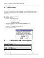
5. Calibration
The ISO-813 is calibrated to its best state of operation. For environment with large vibration,
recalibration is recommended. Before calibrating the ISO-813, user should take care the
following issue:
One stable voltage source (4.9988V)
Diagnostic program :
DIAG813 for MS-WINDOWS 95
MS-WINDOWS 98
MS-WINDOWS NT 4.0
MS-WINDOWS 2000
this program included in the delivered package will guide the user to
proceed the calibration.
Insert disk to 3.5” 1.44MB floppy disk driver then
RUN A:\DIAG\SETUP.EXE
5.1.
Calibration VR Description
There are four VRs on the ISO-813.
VR Num. Description
VR1
A/D Full Scale
VR2
A/D Offset
VR3
A/D Unipolar Offset
VR4
PGA Offset
ISO-813 User’s Manual (Ver.1.2, Oct/2003, IPH-011-12)
----27
ISO813 32-channels isolated analog input card
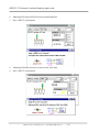
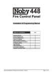
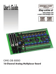
5.1.1. Calibration Step
1. RUN “DIAG813”
2. Apply 0V to AI channel 0 and 4.9988V to AI channel 1
3. Press “CALIBRATION” push bottom
4.
5.
Adjusting VR1 until AI DATA between 2047 and 2048
Press “NEXT” push bottom
2048
0.0
ISO-813 User’s Manual (Ver.1.2, Oct/2003, IPH-011-12)
----28
ISO813 32-channels isolated analog input card
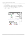
6. Adjusting VR2 until AI DATA between 4094 and 4095
7. Press “NEXT” push bottom
4094
4.9976
8.
9.
Adjusting VR4 until AI DATA between 2047 and 2048
Press “NEXT” push bottom
X16
2048
0.0
ISO-813 User’s Manual (Ver.1.2, Oct/2003, IPH-011-12)
----29
ISO813 32-channels isolated analog input card
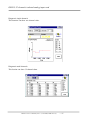
10. The VR3 adjusting is unipolar offset, you can by pass this step if using bipolar input
range of your application.
If you are using unipolar mode , shut down windows and turn off PC then take out
the ISO-813 interface card and change JP2 to unipolar mode. Then insert ISO-813 to isa
bus slot then turn on your PC , RUN “DIAG813” diagnostic program .
Apply 0V to AI channel 0, By pass VR1 , VR2 , VR4 calibration step if there are ready.
Adjust VR3 until AI DATA between 0 and 1.
1
0.002
ISO-813 User’s Manual (Ver.1.2, Oct/2003, IPH-011-12)
----30
ISO813 32-channels isolated analog input card
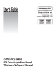
Diagnostic single channels
This function can show one channel value.
Diagnostic multi channels
This fuction can show 32 channels data.
ISO-813 User’s Manual (Ver.1.2, Oct/2003, IPH-011-12)
----31