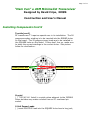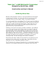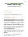
1
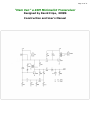
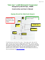
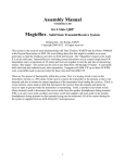
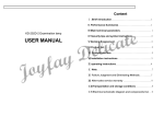
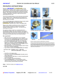
Four State QRP Group
“Ham Can”
A 40M Minimalist Transceiver
Designed by David Cripe, NMØS
Construction and User’s Manual
Congratulations on your purchase of the HAM CAN transceiver, the latest
offering in minimalist amateur radio from the Four State QRP Group! The
HAM CAN is a crystal-controlled CW transceiver, delivering 1/2 to 1W
transmit power, with enough sensitivity and selectivity to receive plenty
of signals. It does all this with only TWO transistors!
Table of Contents
Specifications and Description ............................................. Page 2
Parts List ......................................................................... Page 3
Component Installation ..................................................... Page 4
Soldering Tutorial .............................................................
Page 8
Using The Ham Can ............................................................ Page 9
Schematic ........................................................................ Page 10
Keying Circuit for Electronic Keyer ....................................... Page 11
Page 2 of 11
“Ham Can” a 40M Minimalist Transceiver
Designed by David Cripe, NMØS
Construction and User’s Manual
Specifications and Description
General Description
The ―Ham Can‖ is a minimalist transceiver designed to be very simple
and inexpensive, yet provide good performance. The low cost kit
sacrifices nothing in the way of quality. It features a high quality printed
circuit board, low parts count and fast and easy building. It makes an
excellent first kit for first time builder, and for this reason it was chosen
as the Build Session kit for OzarkCon 2011.
This NMØS design features an innovative power switch. Your straight key
plug also serves as the on and off switch, i.e. Just plugging int the hey
powers up the rig automatically
Designed to be as small as possible and still use through hole parts, it
will fit on top of a 3 oz ham snack can, while a 9 volt battery resides
inside the can, thus making self contained portable rig. Brand names
with cans this size are Armour, Bryan, Fancy Feast and probably many
others. The builder can enjoy a snack while obtaining the enclosure :o)
Receiver
Crystal-oscillator-filter design - Smooth and easy regeneration control
due to 25 turn pot - Direct conversion - Crystal controlled on 7122 kc Adequate sensitivity for 40M - Audio stage drives earpones
Transmitter
Keyed oscillator operating in class C - .5 to 1 watt output into 50 ohms VCC keying - pleasing bell like signal -
Page 3 of 11
“Ham Can” a 40M Minimalist Transceiver
Designed by David Cripe, NMØS
Construction and User’s Manual
Part List
Let's begin construction by taking an inventory of components:
C1
C2
C3
C4
C5
C6
C7
C8
C9
C10
(
(
(
(
(
(
(
(
(
)
)
)
)
)
)
)
)
)
D1
D2
D3
D4
(
(
(
(
)
)
)
)
L1
L2
L3
()
()
Q1
Q2
()
()
2N3866
2N3904
R1
R2
()
()
1.0k
27k
brown-black-red
red-violet-orange
R3
R4
()
()
10k
220k
10-turn pot
red-red-yellow
T1
T2
()
()
T50-2
1k:8 ohm audio
X1
()
7.122 MHz
J1
J2
J3
J4
HS
()
()
()
()
()
1/8 Stereo Jack (Key)
1/8 Stereo Jack (Phone)
RCA Jack (Ant)
9v Battery Clip
Heat Sink
26 AWG
22 AWG
PC Board
680p
681J
220p
221J
10p
100J
1000p
102J
Not Used - Jumper Out
0.047 u
473j
0.47u
0.47uF Electrolytic
1000p
102J
470u
470uF Electrolytic
Not Used - Leave Open
1N4148
1N4148
1N4148
1N4148
T50-2
T50-2
Not Used - Leave Open
()
()
()
3'
2'
Page 4 of 11
“Ham Can” a 40M Minimalist Transceiver
Designed by David Cripe, NMØS
Construction and User‘s Manual
Component Installation
WINDING THE COILS
Let's begin construction! Start off by winding the toroids. Yeah, those
are the least fun part of the whole project, and take the most attention to
detail, but once they are wound, it is all downhill from there.
There are three toroids to
wind. Starting with L1, this is wound
with 22 turns of 26 gauge
magnet wire. This is the thinner of the
two pieces of magnet wire
included in the kit. Cut off about two
feet from the piece, and wind it in the direction shown in the diagram
above. Make sure the wire is pulled snug against the toroid coil form,
without any kinks, and that the turns are evenly distributed around the
core. Turns are counted as the number of times the wire passes through
the center of the core.
Next, cut the 22 gauge wire in half, and wind L2 with 11 turns, in the
same manner as L1.
Finally, we need to wind T1, the RF transformer. The core is wound with
two windings of 11 turns each, one of 22 gauge for the primary, and one
of 26 gauge wire for the secondary. Start with the 22 gauge primary,
and wind it per the diagram. When finished with this, wind the
secondary so that it lies in between turns of the primary, flush to the
core without crossing any of the primary windings. Double check when
finished to be sure that both primary and secondary have 11 turns each.
Cut the legs of each coil so that there is about ½ inch remaining, and set
them aside until later. Now that the hard part is over, let‘s start
soldering!
Page 5 of 11
“Ham Can” a 40M Minimalist Transceiver
Designed by David Cripe, NMØS
Construction and User‘s Manual
Component Installation Cont’d
The component identification and mounting locations are silk screened on
the component side of the PCB. Check off each part as you install them.
Install and solder one part at a time, clipping the leads flush with the
back of the board.
Capacitors
We‘ll start by installing capacitors. Their value is designated by the code
printed on them. Locate the capacitors, and insert them into the board,
spreading their legs slightly at the bottom to keep them from falling back
out when the board is inverted. Solder them in, and trim their leads
flush with the board. Mark them off the list as they are installed.
C1
C2
C3
C4
C5
(
(
(
(
(
)
)
)
)
)
680p
220p
10p
1000p
C6
C7
C8
C9
(
(
(
(
)
)
)
)
0.047u
0.47u
1000p
470u
681J
221J
100J
102J
Not Used - Jumper out using component lead
473j
0.47
102J
470
Diodes
Next, the diodes are to be installed. They are all the same type, so there
is no chance for confusion, but they need to be inserted into the board so
that their body stripes line up with the stripe on the silk screen board
marking.
D1
D2
D3
D4
(
(
(
(
)
)
)
)
1N4148
1N4148
1N4148
1N4148
Page 6 of 11
“Ham Can” a 40M Minimalist Transceiver
Designed by David Cripe, NMØS
Construction and User‘s Manual
Component Installation cont’d
Resistors
Next come the resistors. These are installed in a space-saving ‗hairpin bend‘ manner. The
value of the resistors is designated by three color coded bands. A fourth gold band at the
right side of the resistor indicates 2% tolerance of the resistor value. Install and solder one
at a time, clipping the leads flush with the back of the board when finished.
R1
()
1.0k
brown-black-red
R2
()
27k
red-violet-orange
R3
()
10k
10-turn pot
R4
()
220k
red-red-yellow
Transistors
Be certain that the body of Q1 is spaced above the board by about 1/16‖ so that it DOES
NOT contact the board surface.
( ) Q1 - 2N3866 Install with tab on transistor oriented to outline on pcb.
( ) Q2 - 2N3904 Install with flat on transistor oriented to outline on pcb.
Audio Transformer
Install the audio transformer, T2. Be certain that the primary-side windings are installed
into the correct holes. Solder the mounting tabs into the PCB holes as well.
( ) 1K:8 ohms Install with the side marked P oriented toward Q2.
Connectors
Install the three connectors next. Be certain they are snug against the board before
soldering. Do not overheat the Key and Phone jacks so that the plastic bodies of the
connectors do not soften.
( ) J1
( ) J2
( ) J3
NOTE:
the on
Key Install 1/8 STEREO jack in KEY position indicated on PCB
Antenna Install RCA jack in ANT position indicated on PCB
Install 1/8 STEREO jack in PHONES position indicated on PCB
A 1/8 MONO plug (as used with a straight key) inserted in the KEY jack serves as
and off switch.
Toroids
We need to install the toroidal coils next. The pigtail wire leads of each coil need to be
tinned. The enamel insulation on the magnet wire is solder-strippable, melting clean at the
touch of a well-tinned soldering iron. Tin the leads flush to the body of the toroids. If the
wires do not strip cleanly, the remaining enamel may be cleaned off by scraping with an XActo knife.
Insert the wire pigtails though the holes in the board, and pull them snug before soldering.
Page 7 of 11
“Ham Can” a 40M Minimalist Transceiver
Designed by David Cripe, NMØS
Construction and User’s Manual
Installing Components Cont’d
Toroids (con’t)
RF transformer T1 requires special care in its installation. The 26
gauge secondary winding is to be inserted into the ROUND holes
on the board. The 22 gauge primary leads are to be installed in
the SQUARE holes on the board. If they don‘t line up, make sure
to place the correct windings in the correct holes. See picture
below for clarification..
Primary Green #22
Secondary Red #26
Crystal
( ) 7122 HC-46 Install in crystal outine adjacent to the 2N3866
Some builders may make a socket from an IC machined pin
socket.
9 Volt Power Leads
( ) install POSITIVE lead into the SQUARE hole close to key jack,
Page 8 of 11
“Ham Can” a 40M Minimalist Transceiver
Designed by David Cripe, NMØS
Construction and User’s Manual
Soldering Know How
Because of the simplicity of this kit, it will have appeal as a first project
for beginning kit-builders. For those with little or no experience with
soldering, there are a few things to keep in mind before starting.
It is recommended that a low wattage, 25 to 30 watt, pencil-tip soldering
iron be used. Only rosin-core solder may be used, as acid core plumbers
solder will corrode the board and components. Either lead-free or tinlead solder may be used, though the builder should be aware of the
potential toxicity of lead-based solders.
Soldering is not hard if the proper procedure is followed. The soldering
iron is to be used to heat up the bottom side of the board PC pad and
component lead, and the solder applied to the pad, where it melts and
flows into the hole. Do not melt the solder onto the tip of the iron and
then attempt to dab it onto the joint – a defective connection will result!
After soldering, check the top (component side) of the board, to be sure
the solder has filed the hole completely, and wicked up around the
component lead. Re-heat and apply more solder if necessary.
Burned flux and solder residue will accumulate on the soldering iron tip
and lead to dirty solder joints if not kept clean. Periodically wipe the
soldering iron tip on a dampened sponge to clean it.
The PC board has the reference designators for the component mounting
locations in silk-screened lettering on the component side of the PCB.
Page 9 of 11
“Ham Can” a 40M Minimalist Transceiver
Designed by David Cripe, NMØS
Construction and User’s Manual
Using the Ham Can
To begin, turn the regeneration control R3 fully clockwise. Note: there is
no stop, listen for a light click.
The 1/8‖ MONO key plug connects 9v battery power to the circuit—
unplug when not in use.
Plug in the antenna (matched to 1:1 SWR), earphones, and a straight
key, do not use your electronic keyer. This rig requires a special keying
circuit (described later), or a straight key.
Snap in a 9 volt battery if you used a clip, or hook up leads from a 9 volt
power supply (do not use higher voltage ) OBSERVE POLARITY, there is
no protection diode on the board. Add one in the 9 volt line if you wish,
any 1 amp diode will work fine (1N400x).
The Ham Can does not have a sidetone, so all you will hear is keyclicks
on TX. The regen is very smooth, and you will not hear any clicks when
the RF oscillation commences. If you are connected to an antenna when
the band is active, you will hear stations start to come in, and you will
also hear the rig's oscillation on a nearby CW receiver.
Adjust the 10K trimpot (R3) regeneration control if needed. Start with
pot fully Clockwise, then rotate counter clockwise until receiver
regeneration begins. This will be heard as a weak signal on your big rig,
or you will hear signals and band noise.
Once oscillation begins, turn the pot one or two more turns
counterclockwise to bring receiver volume to max. You should not need
to readjust this pot setting unless the battery voltage droops. When it
does, then another 1-2 CCW turns will be necessary to again peak the receiver volume.
Press straight key - the xmitter should be making 1/2 to 1 watt of
power. You will be able to hear receiver signals while you are
transmitting! How‘s that for full QSK?
Page 10 of 11
“Ham Can” a 40M Minimalist Transceiver
Designed by David Cripe, NMØS
Construction and User’s Manual
39k
2N3866
Page 11 of 11
“Ham Can” a 40M Minimalist Transceiver
Designed by David Cripe, NMØS
Construction and User’s Manual
Keying Circuit For Electronic Keyers
Isolate 9v and
ground from the
Ham Can‘s power
supply
9v
Or use 4.5—5 volts with no
dropping resistor.
Rs
To Key Jack
On Ham Can
5v Reed
Relay
1/8 Mono
Keyer
2N3906
A reed relay keys the Ham Can nicely. Almost any reed relay can be
used. The first one tried was a Radio Shack #275-232, another suitable
one is the Coto 9007, Mouser # 816-9007-05-01. These are 5 volt relays
and need the dropping resistor Rs. Rs=4 volts divided by the coil current
in amps. Some relays have an internal spike snubbing diode, add an
external one if your‘s doesn‘t. Double click the link below to hear an on
the air recording of the Ham Can‘s signal.