1
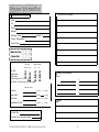
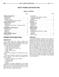
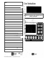
+ User Instructions
NOTES
ATTENTION: This information is highly confidential. Keep this
booklet in a Secure place.
0 1990 by C E I
PN 8402
Technical Manuals Online! - http://www.tech-man.com
CONTENTS .
INTRODUCTION
Master Keypad Reference Diagram (centerfold) . . . . . . . . . . . . . . . . . . . . . . . . . . . . . . . 8 - 9
Your new security system has many sophisticated features. It has been customized
by your installer for your home or business. The master keypad, which is wired
irectly to the control center, is your link to the system. The control center is
mounted out of sight in a metal box. The master keypad and any wireless keypads or
handheld transmitters are the only things you need to control the system.
Page
System Information (inside back cover) . . . . . . . . . . . . . . . . . . . . . . . . . . . . . . . . . . . . . . . .16-17
Introduction . . . . . . . . . . . . . . . . . . . . . . . . . . . . . . . . . . . . . . . . . . . . . . . . . . . . . . . . . . . . . . . . . . . . . . . ..*..................... 1
System Maintenance . . . . . . . . . . . . . . . . . . . . . . . . . . . . . . . . . . . . . . . . . . . . . . . . . . . . . . . . . . . . . . . . . . . . . . . . . 1
System Overview . . . . . . . . . . . . . . . . . . . . . . . . . . . . . . . . . . . . . . . . . . . . . . . . . . . . . . . . . . . . . . . . . . . . . . . . . . . . . . . . . . . . . . 1
Monitoring Service . . . . . . . . . . . . . . . . . . . . . . . . . . . . . . . . . . . . . . . . . . . . . . . . . . . . . . . . . . . . . . . . . . . . . . . . . . . . . . . . . . . . .2
Light Operation . . . . . . . . . . . . . . . . . . . . . . . . . . . . . . . . . . . . . . . . . . . . . . . . . . . . . . . . . . . . . . . . . . . . . . . . . . . . . . . . . . . . . . . . . . .2
Manual Alarms . . . . . . . . . . . . . . . . . . . . . . . . . . . . . . . . . . . . . . . . . . . . . . . . . . . . . . . . . . . . . . . . . . . . . . . . . . . . . . . . . . . . . . . . .. . 2
User Codes. . . . . . . . . . . . . . . . . . . . . . . . . . . . . . . . . . . . . . . . . . . . . . . . . . . . . . . . . . . . . . . . . . . . . . . . . . . . . . . . . . . . . . . . . . . . . . . .2
Arming & Disarming . . . . . . . . . . . . . . . . . . . . . . . . . . . . . . . . . . . . . . . . . . . . . . . . . . . . . . . . . . . . . . . . . . . . . . . . . . . . . . . . . 3
Entry/Exit Delays . . . . . . . . . . . . . . . . . . . . . . . . . . . . . . . . . . . . . . . . . . . . . . . . . . . . . . . . . . . . . . . . . . . . . . . . . . . . . . . . . . . . . . 4
System Advisory Tones (SAT’s) . . . . . . . . . . . . . . . . . . . . . . . . . . . . . . . . . . . . . . . . . . . . . . . . . . . . . . . . . . . . . . 4
Burglary Violation Beeps . . . . . . . . . . . . . . . . . . . . . . . . . . . . . . . . . . . . . . . . . . . . . . . . . . . . . . . . . . . . . . . . . . . . . . . . . . 5
Display Windows . . . . . . . . . . . . . . . . . . . . . . . . . . . . . . . . . . . . . . . . . . . . . . . . . . . . . . . . . . . . . . . . . . . . . . . . . . . . . . . . . . . . . . 5
Clearing Alarm Memory.. .........................................................................
5
Trouble Messages.. .................................................................................
6
Fire Trouble.. ...........................................................................................
6
Testing.. ...................................................................................................
6
2nd User Codes.. ....................................................................................
6
Chime Mode.. ..........................................................................................
7
Bypassing.. .............................................................................................
7
e Smoke Detectors.. .................................................... 7
Resetting Hardwire
An alarm system is not a substitute for vigilance and preparedness. You should have
plans of action in the event of fire, intrusion, or any other emergency.
Daily, routine operation of the system will require you only to simply arm and
disarm it by pressing the appropriate keys. However, because this alarm system is
designed to tell you when it is experiencing anything abnormal (an alarm, a low
battery, or an electronics problem), you need to know how to respond in these situations. This manual will explain the system’s operation and tell you what to do if the
system gives you a visual or audible message.
Optional features in your system are indicated by boxes 0 which your installer
will mark to show that you do or do not have a particular feature. Boxes that are not
checked may be ignored.
Before reading further in this manual, turn to the Master Keypad Reference Diagram
on pages 8-9 and take a few minutes to familiarize yourself with the positions of the
keys and displays. This diagram will also be helpful for future reference as you use
your system. Your installer has filled in the System Information section (inside the
back cover of this manual) with other facts about your system.
SYSTEM MAINTENANCE
Be sure to have your installer go over the system with you until you are familiar with
, its operation and the complete procedures for testing all system components. No
ectronic product can perform better than the care and maintenance it receives. This
manual contains instructions on how you can test your alarm system. Individual test
and maintenance instructions are also provided with many of the accessory components that make up your system. Keep those instructions with this booklet.
The manufacturer of this equipment strongly urges that you and your installing
company enter into a periodic service and maintenance agreement so that capable
service technicians can help assure that your system is operating properly.
In Case of an Alarm . . . . . . . . . . . . . . . . . . . . . . . . . . . . . . . . . . . . . . . . . . . . . . . . . . . . . . . . . . . . . . . . . . . . . . . . . . . . . . . .
10
SYSTEM OVERVIEW
AC Power & Backup Battery . . . . . . . . . . . . . . . . . . . . . . . . . . . . . . . . . . . . . . . . . . . . . . . . . . . . . . . . . . . . . . . . . . .
10
Duress Codes . . . . . . . . . . . . . . . . . . . . . . . . . . . . . . . . . . . . . . . . . . . . . . . . . . . . . . . . . . . . . . . . . . . . . . . . . . . . . . . . . . . . . . . . .
60
Fire Detection & Emergency Evacuation . . . . . . . . . . . . . . . . . . . . . . . . . . . . . . . . . . . . . . . . . . . . . . . . .
11
This security system can be set up in a variety of ways, using radio frequency (RF)
transmitters, hardwire zones, or a combination of the two. RF transmitters send a
radio signal to the control center. Hardwire zones are physically connected to the
control by wires. This system contains:
Things You Should Know About RF Devices . . . . . . . . . . . . . . . . . . . . . . . . . . . . . . . . . . . . . . . . . . 12
Limitations of the System . . . . . . . . . . . . . . . . . . . . . . . . . . . . . . . . . . . . . . . . . . . . . . . . . . . . . . . . . . . . . . . . . . . . . . . .
Technical Manuals Online! - http://www.tech-man.com
13
0 All RF transmitters
0 All hardwire zones
0 A combination of both
1
Cl MONITORING SERVICE (CANCELLING ACCIDENTAL ALARMS)
ARMING & DISARMING THE SYSTEM
You may have elected to subscribe to a monitoring service. If so, reports will be sent
Some sensors in your system are always armed and will trigger an alarm whenever
they are tripped. They are pre-set by your installer and you cannot, in most cases,
irn them off. These would include protection for fire, police, emergency, etc.
via telephone lines in the event of alarms or system trouble. The service then alerts
the appropriate authorities. Refer to the System Information pages for a list of the (
reports you have selected for transmitting to the service. Be aware that you need to
call and cancel any accidental alarm. It is very expensive to have emergency
vehicles respond to unintentional alarms. You may be charged a fee for this type of
response.
0 LIGHT OPERATION
Your system may be set up to turn on selected lights when an alarm occurs or when
you intentionally activate them using a portable transmitter. Your installer will
explain how lights are tied into your system. The facts concerning selected lights
and their operation are recorded in the System Information pages.
MANUAL ALARMS
In an emergency, you can trigger an alarm from the master keypad by pressing both
“Fire” symbol keys simultaneously for a fire alarm or both “Police” symbol keys
simultaneously to activate a police alarm. If your system is connected to a monitoring service, the service will dispatch the appropriate emergency vehicles.
The burglary intrusion sensors in the system are routinely armed and disarmed
(turned on and off) during the day. Burglary protection consists of perimeter and
interior sensors. Perimeter sensors are usually located on windows and doors, and
you normally leave these sensors armed when you are home. Interior sensors, such
as motion detectors, protect the interior of your residence and are normally armed
only when you are away.
Burglary sensors will be set for either instant or delay triggering when your system is
armed. If an instant sensor is tripped, an immediate alarm will sound. Delay sensors
provide time for you to enter or exit the building without causing an alarm.
The burglary protection in your system can be armed to three different modes. The
STAY and AWAY lights on the master keypad indicate the mode.
AWAY: No one is in the protected area. All interior and perimeter
sensors are on. You will normally put the system in Away when
you leave the premises.
STAY: You are inside the premises and want to be alerted if
USER CODES
someone tries to enter. Perimeter sensors are on. Interior sensors
are off, allowing you to move about freely.
User codes are four-digit sequences of keys activated by either hardwire or wireless
keypads. These codes allow you to arm, disarm and change some features on your
system. You have approximately ten seconds from the time you begin to finish
pressing the keys. If you make a mistake, simply press a digit that is not part of your
code. This will clear the error and let you start over. You may also wait for the ten
seconds to expire before beginning again. There are three types of user codes:
Master Code: This is the permanent code programmed during
the installation of your system. It is recorded on the System Information pages. Memorize it and do not give it to anyone except
those you wish to have complete access to your alarm system.
Cl NIGHT: You have retired for the evening and want additional
protection in selected areas. All perimeter protection is fully
armed as in the other modes. Certain interior sensors (selected by
you and your installer) are also on. For example, you may choose
to have downstairs interior sensors on while upstairs sensors
remain off.
Your installer will indicate the arming method you have chosen below:
0 Single-Digit Arming (must disarm first to change modes)
Arm to AWAY: Press ‘AWAY’ key *
Arm to STAY: Press ‘STAY’ key
0 Arm to NIGHT: System is already armed to STAY:
Press ‘STAY’ key
2nd User Code: This is a temporary code you can assign to
allow others to use your system without them knowing the master
code. See “Assigning a 2nd User Code” for more information.
0 Duress Code: Few installations will require this type of
code. If you have decided on this option during installation, you
must be extremely careful and use it only when you are in direct
personal danger. See “Duress Codes” for a complete explanation.
2
Technical Manuals Online! - http://www.tech-man.com
I
Cl Coded Arming
Arm to AWAY: Press ‘AWAY’ key, then enter user code
Arm to STAY: Press ‘STAY’ key, then enter user code
0 Arm to NIGHT: System is already armed to STAY:
Press ‘STAY ‘ key, then enter user code
3
1
Protest SAT’s: 4 quick beeps repeating every 45 seconds. These tones indicate that
a trouble message or alarm has just been displayed in the master keypads windows.
The keypad’s “Ready” light will also blink to indicate these conditions. See the
Master Keypad Reference Diagram for further information.
Press the * key to silence the protest SAT’s. The message will remain in the
windows. If the windows are not cleared (see later sections), a set of protest SAT’s
will follow the normal arm/disarm SAT’s whenever the system’s armed mode is
changed. The protest SAT’s serve as a reminder that there is still a window message
that has not been cleared or acted upon.
0 ARM/DISARM EXTERIOR CHIRPS
Your system may be set up to allow you to arm/disarm from outside using a handheld transmitter. If so, the exterior alarm sirens will “chirp” (quick “pops”) in the
same pattern as the interior SAT’s. These chirps allow you to verify the current
system status without going inside. If trouble occurred while you were away (or if a
previous message was not cleared), four protest chirps will be added to the end of the
arm/disarm chirps.
DISARMING
To disarm your system or to turn off an alarm, just enter your user code. Once again,
if your system is connected to a monitoring service, be sure to cancel any accidental
alarms to prevent emergency personnel from responding.
ENTRY/EXIT DELAYS
When you arm to the AWAY mode, there is a delay period to allow you time to exit
the premises. Likewise, there is an entry delay time so you can enter the building
and disarm the system before the alarm sounds. You should leave and return only
through designated doors protected with delay sensors. The times for exit and entry
delays have been recorded by your installer on the System Information pages.
During the entry delay, a “pre-alarm” tone will sound to remind you that the system
is armed and must be either disarmed or re-armed. An alarm will occur at the end of
the entry delay time if no action is taken.
0 When your system is set up for the “Interior Follower” feature, instant interior
sensors become delay sensors if you first enter through your delay door. You can
now walk in front of motion detectors on the way to the keypad after you enter.
SYSTEM ADVISORY TONES (SAT’s)
SAT’s are beeps that sound inside the home and are normally heard at arming and
disarming. They indicate the arming status of the system, and will also advise you if
a trouble message or an alarm memory has been displayed in the keypad’s windows.
SAT’s will also sound when remote transmitters are used to arm or disarm the
system.
1 beep = AWAY mode
2 sets of 2 beeps q NIGHT mode
2 beeps = STAY mode
3 beeps q Disarmed
4
Technical Manuals Online! - http://www.tech-man.com
BURGLARY VIOLATION BEEPS
For your protection, this system lets you know if a burglary alarm has occurred in
your absence. If an alarm has occurred, warning beeps will sound over all speakers
for three seconds. These violation beeps will immediately start when you enter the
premises and trigger the entry pre-alarm. If you are using a handheld transmitter
from outside the building and send a status request or disarm command, the warning
will also sound.
Once the sirens stop, burglary alarms are also “remembered” in two other ways.
The “Ready” light flashes rapidly and, if part of your system, selected house lights
ill come on and remain on.
CAUTION: Anytime a prior burglary alarm is indicated, you
should leave the area immediately and contact the appropriate
authorities. Do not go into the building.
From this point, all information applies to the master keypad. For
quick reference, refer to the Master Keypad Reference Diagram.
DISPLAY WINDOWS
The display windows under the hardwire keypad door indicate a variety of system
conditions. See the System Information pages for transmitter and/or hardwire zone
locations.
CLEARING ALARM MEMORY
The cause of an alarm will be indentified in the display windows as soon as it occurs.
To clear the memory, press and hold the * key until the second beep sounds. Protest
beeps will be tagged onto the end of arm/disarm SAT’s until the alarm message is
cleared.
5
RESPONDING TO SYSTEM TROUBLE MESSAGES
Refer to the table in the Master Keypad Reference Diagram for messages displayed
if there is a system problem (“E” messages). In some cases, you will be able to take
care of the trouble yourself. Major problems such as blown fuses will only clear
when the trouble has been corrected. Since your system’s integrity is compromised
by major problems, you should call your installer as soon as possible.
Protest beeps will be tagged onto the end of all arm/disarm SAT’s until the trouble
message has been cleared.
Transmitter low battery messages can be cleared by pressing and holding the * key
until the second beep. Refer to the individual transmitter instructions for battery
replacement or notify your installer.
An “E AC” message (AC power loss) indicates that the control center is operating
only on the standby battery and not on AC power. First, check that your neighborhood is not experiencing a power outage. Next, verify that the control center is still
plugged into the wall outlet and then check the circuit breakers in your house. Call
your installer if you are unable to find the reason for the trouble message.
FIRE TROUBLE
ASSIGNING A 2nd USER CODE
Sometimes you may want to temporarily allow others to arm and disarm your system
_ (such as employees, repairmen, babysitters, etc.). You can do this by adding a 2nd
user code which allows them to use the system without knowing your master code.
The 2nd user code can be erased easily later. To add or change a 2nd user code:
1) Hold the 5 key until second beep, then enter MASTER code.
2) Slow beeps will sound.
3) Key in the new 2nd user code within 10 seconds.
To erase a 2nd user code, repeat the above process, but key in the MASTER user
code as the 2nd user code.
CHIME MODE
“Chime” refers to the tone which sounds when any of your system’s perimeter
burglary sensors are triggered while the system is disarmed. Since these sensors are
usually on your entry/exit doors, the tone will alert you when the doors are opened.
You can easily turn the chime mode on or off:
1) Press and hold the 2 key until second beep. Current chime
mode will be displayed in the windows.
2) Enter user code within eight seconds after releasing the 2 key to
change chime mode.
When window messages start with an “F”, it means there is trouble with part of your
fire protection. This could mean either a low battery in an RF smoke detector or a
problem on a hardwire fire zone. If the problem is a low battery, see the instructions
for the individual transmitter. If it’s a hardwire fire zone, see “Resetting a Hardwire
Smoke Detector.”
0 BYPASSING A CHANNEL OR ZONE
TESTING THE SYSTEM
At times you may want to have a particular section of your system’s burglary
protection disarmed while the rest of it remains armed. To do this:
Be sure your installer fully explains how to test each device in your system. The
system should be tested once each week to ensure all parts are functioning as they
should. Follow this procedure:
1) Disarm the system.
2) Press and hold the 1 key until second beep.
3) Enter user code. Displays flash “8 88”. The system is now in
the test mode.
4) Press the * key to test sirens.
5) Check each sensor by opening protected doors and windows,
entering areas covered by motion detectors, and operating handheld transmitters. Perform any other procedures described and
listed by your installer on the System Information pages. Be
sure that the keypad or interior speakers beep each time
you operate a sensor to confirm that it is working.
6) Press the 1 key to exit test mode. If no tests are done for 10
minutes, the system will automatically revert to normal operation.
0 See the back cover for instructions from your installer on testing the system and
phone link to your monitoring service.
Technical Manuals Online! - http://www.tech-man.com
1) Disarm the system.
2) Press and hold the 3 key until second beep.
3) Enter user code within eight seconds, then press the number of
the channel or zone you want to bypass.
To restore a channel or zone, repeat the above sequence of entries. All bypasses are
cleared at disarm (or simply when a user code is entered by itself ).
0 RESETTING A HARDWIRE SMOKE DETECTOR
Some types of hardwire smoke detectors require resetting after they send an alarm
and will not send another alarm until they are reset. If a detector needs to be reset or
there is some problem with it, a trouble message will appear in the display windows.
To reset these detectors:
1) Press and hold the 4 key until second beep.
2) The display windows will clear when the detector resets.
If the detector does not reset properly, the protest beeps will sound and the display
windows will not clear. If this happens, make sure you have cleared any smoke from
the area, then try again. If the detector still won’t reset, call your installer.
7
READY LIGHT
On when all system functions
are O.K.
Fast blink for burglary violation.
. Slow blink when trouble or
alarm memory information is
displayed in windows.
* Off when a perimeter hardwire
burglary loop is unsecured.
l
AC POWER LIGHT
Indicates system has
AC power.
l
\
FIRE ALARM KEYS
11
AUX KEY & LIGHT
0 Disabled
II
0 AUX key set for
AWAY LIGHT
On when the system
is armed to AWAY
mode.
Note: Both STAY and
AWAY lights are on in
NIGHT mode.
* KEY
. Press to silence recurring
45-second protest tones.
. Press and hold until 2nd beep to
clear alarm memory and
transmitter low battery indication.
User Code Required
QYes
~NO
STAY LIGHT
On when the system is
armed to STAY mode.
Note: Both STAY and
AWAY lights are on in
NIGHT mode.
AWAY KEY
0 Press to arm system to AWAY
_----------
l2imi-l
0 Press then enter user code to arm
system to AWAY mode.
-I-
@ml
What the Messages in the Display Windows Mean
ALARM IDENTIFICATION (press and hold * key to erase)
(See “System Information” for locations)
A 01 thru A 52
Transmitter #
A H1 thru A H8
Hardwire Zone #
A HF
Master Keypad Fire Alarm
A HP
Master Keypad Police Alarm
A HE
Master Keypad “AUX” key
when set to medical
FIRE TROUBLE
F 33 thru F 40
RF Smoke Detector Low Battery
F H1 thru F H8
Hardwire Smoke Detector Trouble
BYPASSING
b H1 thru b H8
Bypassed Hardwire Burglary Zone
u H1 thru u H8
Unsecure Hardwire Burglary Zone
b 01 thru b 04
Bypassed RF Channel
SYSTEM TROUBLE
E 01 thru E32
Channel # of Low Transmitter Battery
Replace battery or call installer.
E AC
AC Power Loss -Try to ascertain
cause (breakers, general outage,
etc.). As last resort call installer.
0
E Fu
Blown Fuse in Control Center
c
E bb
Control Center Backup Battery
Trouble
0
Memory Error
E EE
II-
0 Press again to arm system to
NIGHT mode.
__----- ---_
0 Press once followed by user code to
arm system to STAY mode.
0 Press once followed by user code to
arm system to NIGHT mode.
CHIME MODE
Press and hold until 2nd
beep to view.
- Enter user code within 8
/ seconds to change.
l
TEST MODE
- Press and hold until 2nd
. Enter user code (‘8 88’ will
flash in windows).
Press 1 to exit test mode.
l
o System integrity is compromised. Call installer immediately.
Technical Manuals Online! - http://www.tech-man.com
8
.
STAY KEY
0 Press once to arm system to STAY
I
BYPASS BURGLARY
PROTECTION
0 Disabled
- 0 Transmitters
0 Hardwire Zones
Press and hold until
2nd beep.
* Enter user code.
Press xmtr/zone #.
l
RESET HARDWIRE
SMOKE DETECTORS
* Press and hold until 2nd
beep.
0 Not used.
l
9
ADD/CHANGE 2nd USER
CODE
- Press and hold until 2nd
beep, then enter MASTER
user code.
- Key in 2nd user code
within 10 seconds.
IN CASE OF AN ALARM
.
If you are using a monitoring service, remember to immediately notify them of
accidental alarms.
If you return home to find your system has had an alarm, do not enter the building,
because an intruder might still be inside. Call the police from a neighbor’s house or
a public telephone.
It is suggested that you, your family, and your employees contact your local fire and
police departments, your doctor, and your alarm dealer for advice on what to do in
emergency situations. Make sure everyone in the protected area knows what to do in
the event of an emergency.
AC POWER & BACKUP BATTERY
The green AC Power light on the master keypad will be on while normal 110 volt
AC power is running the control center. In the event of an AC power loss, the light
will go out and the letters “E AC” will appear in the master keypads displays. An
emergency backup battery will automatically take over and should power the control
center for many hours. To conserve battery power, the keypad windows will go
blank after about five minutes. Pressing any key on the keypad will restore window
information for two minutes. When AC power returns, the battery will recharge
itself to full capacity. Prolonged power failure may require up to 24 hours for a
complete recharge.
If the power light goes off and there is no apparent neighborhood power outage,
check your circuit breakers or fuse panel and the system’s plug-in transformer.
0 Protest SAT’s have been programmed to start
AC power. Press the *key to silence them.
after the loss of
0 The system has been programmed to notify the central monitoring service
after the loss of AC power.
Backup Battery
The control center monitors its backup battery in two ways. First, the system checks
the battery voltage during AC power outages. Second, during normal operation, the
system carries out a battery test every 24 hours. In either case, when the battery’s
capacity drops below a fixed level, the protest SAT’s will start and the letters “E bb”
will appear in the keypad’s display windows,
If the battery message appears while the AC power is on, it means the battery has
failed the 24 hour automatic test and may be unable to power the control center in an
emergency. The keypad trouble message will not clear until a valid battery test is
performed.
0 The system has been programmed to notify the central monitoring service for a
low battery during AC outages or failed battery during 24 hour test.
Technical Manuals Online! - http://www.tech-man.com
10
The battery is also automatically tested each time the control center is placed in the
test mode for system testing. If the battery test fails then, “E bb” will be displayed in
the keypad windows when the test mode is exited. Once again, call your installing
company.
0 DURESS CODES
Have your installer carefully and completely explain the use of a duress code. A
duress code may be used at any time in place of either a master code or 2nd user
code such as when arming or disarming the system. Using the duress code will send
a silent alarm to the monitoring service. Police will have been instructed to respond
to a possible hostage situation. Immediately notify the monitoring service if this
code is entered in error because this could endanger anyone in the area.
The duress code is entered by adding 2 to the last digit of either your master code or
2nd user code. For example, if the master were 4-3-2- 1, the duress code would be
4-3-2-3. To block duress codes from temporarily assigned 2nd user codes, choose a
code that ends in 4 or 5 so that it’s impossible to add 2 to the last digit.
FIRE DETECTION & EMERGENCY EVACUATION
Every family or business should take steps to establish a plan of escape in the event
of a fire. This plan should be practiced regularly and discussed with all residents.
Your new security system may or may not include fire detection depending on the
options you selected and the local regulations and codes for your area. Even if your
residence is without fire detection devices, the information listed below should be
heeded. Even when previously installed detection devices are not part of your new
system, they also require regular testing and upkeep. The buildup of common household dust can cause smoke detectors to fail when needed or to false alarm when no
fire is present. Carefully read the instructions included with your fire detection
devices for complete safety information. Your installing dealer should be asked
about a regular maintenance program which includes all fire detection devices.
As a minimum, the following steps should be used in establishing your
evacuation plan:
1) Be sure your installer explains, and that you fully understand,
the fire protection part (if any) of your alarm system.
2) Have your installer demonstrate the audible fire alarm tones.
Then learn how to demonstrate them yourself.
3) BE PREPARED. Perform regular fire drills. Use them to
assure that everyone recognizes the alarm signals, knows the
escape routes and can respond properly to an actual alarm.
4) Children tend to hide in times of crisis. It is important that they
be instructed carefully.
5) Draw a floor plan and select at least two escape routes from
each room. Pay particular attention to the bedrooms since many
fires occur at night when everyone is asleep. It may be necessary to provide rope ladders for rooms above the first floor.
11
6) Establish a meeting place outside where everyone can meet and
insist that all family members meet there. This will avoid the
tragedy of someone re-entering the house to look for someone
who is actually safe. Emphasize that no one is to return to a
burning building.
7) Use a neighbor’s phone to summon the fire department. Leave
the job of extinguishing the fire to trained experts.
Be sure everyone is reminded:
1) ESCAPE FAST. NEVER stop to pack or search for valuables.
2) In heavy smoke hold your breath and stay low, crawling if
necessary.
3) Opening a closed door can be extremely hazardous. If you must
go through a closed door, check to see if the door is hot to the
touch. If it is, do not open it! Find another means of escape.
THINGS YOU SHOULD KNOW ABOUT RADIO FREQUENCY
DEVICES
Although radio transmission links have proven themselves by providing dependable
communication, you need to have full knowledge of their limitations and restrictions
prior to using your system. Some of the areas you should be aware of:
1) Transmitters have limited power and therefore limited range
because they must comply with FCC Rules and Regulations as
Part 15 devices.
2) Transmitter batteries should be routinely changed once a year
even though their useful life under normal operating conditions
should easily exceed this period.
3) Receivers may be blocked by other signals occurring near their
operating frequency.
4) Radio reception characteristics of the system may be changed
when large appliances, mirrors, foil wallpaper, etc. are added or
moved within the home.
5) Because of changing conditions such as those listed above, portable handheld devices should be tested from all anticipated
locations during both the installation tests and during the weekly
customer tests.
Attention!
This Alarm System Has Some Limitations
Capricorn Electronics, Inc. manufactures some of the most advanced security
systems in the industry. However, even the most advanced security system cannot
be guaranteed to warn the end user in every case of fire, unauthorized entry, or other
emergencies.
An alarm system is not a substitute for vigilance and preparedness. Users should
have plans of action in the event of fire, intrusion, or any other emergency.
An alarm system can only operate properly if recommended maintenance procedures
are observed. The most frequent cause of alarm malfunctions is inattention to
maintenance. The system should be tested once each week to be certain components are working. In the case of RF components, special attention should be paid to
the batteries. Replace weak batteries or those over one year old with fresh batteries
according to the instructions provided with each component.
Here are some of the many reasons why a security system can fail to function as
anticipated:
1) Some professional thieves know techniques for disabling alarm systems, or they
may have had an opportunity to “case” the property to find unprotected openings
through which they may enter undetected.
2) It may not be possible for a user to reach and operate a panic button fast enough
to activate the system in an emergency.
3) Power and maintenance requirements may not have been observed. Alarm
sensors, such as passive infrared detectors, RF (radio frequency) transmitters, smoke
detectors and other devices must have proper power to operate correctly. Battery
operated units must be equipped with fresh batteries of the proper voltage (see
instructions for checking and changing batteries). AC-powered units will not operate
if their power supplies are cut off. Backup batteries in AC-operated units should also
be checked regularly.
4) Radio frequency (RF) transmitting devices may be compromised. RF devices
depend solely on proper installation for predictable operation. If the end user
changes the RF characteristics of the structure (e.g., moving large appliances, use of
amateur radio broadcasting equipment by anyone in the vicinity, installing machines
with large electric motors, installing foil-backed wallpaper, or many other possibilities),
certain RF devices may cease operating properly. The installing dealer should be
consulted if any changes are made within a building where RF devices are used.
5) Smoke detectors may not operate for many reasons. The Federal Emergency
Management Agency has published statistics that indicate smoke detectors fail to
warn building occupants in as many as 35% of all fires. Smoke detectors can fail to
operate for a variety of reasons, including the following:
Improper positioning.
Smoke is in an enclosed area where it cannot reach the detector
(such as in chimneys, in walls, on roofs, or on the other side of
closed doors).
Fire is in another area of a building, e.g., a first-floor detector may
not sense a basement fire.
A smoke detector cannot make up for failure to observe common
sense rules of fire safety. A detector may not warn about hazards
l
6) Periodic testing will reveal any new source of interference or a
failure of the system.
7) The receiver can only respond to one transmitter signal at a
time.
l
l
l
12
Technical Manuals Online! - http://www.tech-man.com
13
such as children playing with matches, arson, smoking in bed,
improper storage of hazardous materials, violent explosions,
escaping gas, or overloaded electrical circuits.
Even if a smoke detector operates as expected, due to the nature
of a particular fire and the location of detectors, the detector may
not provide sufficient warning to allow all occupants to safely
escape the building.
6) People located on the other side of closed or partially open doors, deep sleepers,
or hearing-impaired persons may not be alerted by alarm warning devices such as
sirens, horns, bells, etc., no matter how loud. Even individuals who have normal
hearing and are awake may not hear the warning devices if the sound is unintelligible
because of the noise of home entertainment equipment (e.g., TV, stereo, or radio),
appliances (e.g., air conditioners), or the noise of passing traffic.
7) Passive Infrared Detectors (PIR’s) can only detect intrusion in the area covered by
their detection beams, as determined by choice of lenses, mounting height, and
adjustment of sensors. PIR’s cannot sense intrusion that takes place behind closed
doors, walls, ceilings, glass doors or partitions, or windows. PIR’s do not detect
motion, but instead sense increases of temperature within the range of their beams.
Tampering with any part of the optical system of PIR’s (e.g., painting, spraying any
material, masking) can reduce detection ability. Performance of PIR’s can decrease if
the ambient temperature in the area covered by their beams increases to 90” to
105°F.
8) Even if the alarm system works as expected, building occupants may not have
enough time to protect themselves from the emergency situation. Further, authorities
may not respond appropriately to a monitored alarm system.
9) The telephone lines needed to send alarm signals to a monitoring station may be
out of service, or may have been tampered with by an intruder.
10) Components of the system, like all electrical devices, are subject to failure.
l
FCC Compliance
This equipment generates and uses radio frequency energy and if not installed and
used properly, that is, in strict accordance with the manufacturer’s instructions, may
cause interference to radio and television reception. It has been type tested and
found to comply with the limits for a Class B computing device in accordance with the
specifications if Subpart J of Part 15 of FCC rules, which are designed to provide
reasonable protection against such intereference in a residential installation. However, there is no guarantee that interference will not occur in a particular installation.
If this equipment does cause radio or television interference, which can be determined by turning the equipment off and on (be sure to include the backup battery),
the user is encouraged to try to correct the interference by one or more of the
following measures:
1) Re-orient the TV or radio antenna.
2) Move or relocate the main security control away from TV or
radio.
3) Plug the transformer for the main security control into a different
outlet so that the receiver and control are on different branch
circuits.
4) If necessary, the user should consult the installing alarm dealer
or an experienced radio/television technician for additional suggestions.
The user may find the following booklet prepared by the Federal Communications
Commission helpful:“How to Identify and Resolve Radio-TV Interference Problems.”
This booklet is available from the U.S. Government Printing Office, Washington, DC
20402. Stock No. 004-00-00345-4.
Although Capricorn Electronics maintains high standards of quality, users should be
aware that components can fail at any time.
While many insurance companies offer premium discounts for home and business
owners who install alarm systems, do not consider this system a substitute for
prudent insurance coverage for buildings and possessions.
Users of alarm systems should be aware of new alarm products and system improvements for the sake of their own safety and the safety of their loved ones.
14
Technical Manuals Online! - http://www.tech-man.com
Warranty information
EIl~tics, Inc. (C!H) &es not warrtknty these products to ~.
extends only to wholesale custqmers who buy direct from CEI or
normal distribution channels. Consumer warranties and service
, are provided only by the dealer who installed your s~~.~
maintain and service it. Comers should ask thejr pe+e~
deaIer’s warranties and/or maintenance agreements. There
@ising
or liabilities on the part of CEI for consequential
outofarincormectionwiththeuseorperformanceofthisproductorother~
da&&es with respect to loss of property, profit, revenue, cost of removal, instalIation, or re-hs#llation. CEI makes no guaranty or warranty, including any implied
warrauty of merchantability or fitness regarding these products. A copy of CEI’s
complete dealer warranty is included with the main control panel’s instal&ion
instrnctions.
15
‘ r a n s m i t t e r # Locations
Emergency Telephone Numbers
Police
Fire
Doctor
Neighbor
Account #
Monitoring Service
Security Representative
Service Phone
Local Alarm
Audible Silent
Reports to Monitor
Yes
No
Fire Alarm
II
cl
Burglar Alarm
:
Police Alarm
:
;
Medical/Special Alarm 0 0
:
(see “Notes” on back cover for other reports)
:
0 Hardwire Zone Locations
Zone #
:
1
Alarm Siren Tones
Fire Alarm
cuts off in - minutes.
Burglar Alarm
cuts off in
Police Alarm
cuts off in - minutes.
Medical/Special Alarm
cuts off in - minutes.
5
_ _
2
6
3
7
4
6
minutes.
0 Lights
Exit Delay Time
Entry Delay Time (pre-alarm sounds)
Technical Manuals Online! - http://www.tech-man.com
16
17