1
UC-8430 WinCE User’s Manual
First Edition, August 2010
www.moxa.com/product
© 2010 Moxa Inc. All rights reserved.
Reproduction without permission is prohibited.
UC-8430 WinCE User’s Manual
The software described in this manual is furnished under a license agreement and may be used only in accordance with
the terms of that agreement.
Copyright Notice
Copyright ©2010 Moxa Inc.
All rights reserved.
Reproduction without permission is prohibited.
Trademarks
The MOXA logo is a registered trademark of Moxa Inc.
All other trademarks or registered marks in this manual belong to their respective manufacturers.
Disclaimer
Information in this document is subject to change without notice and does not represent a commitment on the part of
Moxa.
Moxa provides this document as is, without warranty of any kind, either expressed or implied, including, but not limited
to, its particular purpose. Moxa reserves the right to make improvements and/or changes to this manual, or to the
products and/or the programs described in this manual, at any time.
Information provided in this manual is intended to be accurate and reliable. However, Moxa assumes no responsibility for
its use, or for any infringements on the rights of third parties that may result from its use.
This product might include unintentional technical or typographical errors. Changes are periodically made to the
information herein to correct such errors, and these changes are incorporated into new editions of the publication.
Technical Support Contact Information
www.moxa.com/support
Moxa Americas
Moxa China (Shanghai office)
Toll-free: 1-888-669-2872
Toll-free: 800-820-5036
Tel:
+1-714-528-6777
Tel:
+86-21-5258-9955
Fax:
+1-714-528-6778
Fax:
+86-10-6872-3958
Moxa Europe
Moxa Asia-Pacific
Tel:
+49-89-3 70 03 99-0
Tel:
+886-2-8919-1230
Fax:
+49-89-3 70 03 99-99
Fax:
+886-2-8919-1231
Table of Contents
1.
Introduction ...................................................................................................................................... 1-1
Overview ........................................................................................................................................... 1-2
Model Descriptions and Package Checklist .............................................................................................. 1-2
Software Specifications ....................................................................................................................... 1-2
Application Development Environment ........................................................................................... 1-3
Networking and Communications Capabilities.................................................................................. 1-3
Supported Servers and Daemons .................................................................................................. 1-3
Graphics and Multimedia Tools ...................................................................................................... 1-4
Firmware Build Versions ...................................................................................................................... 1-4
Memory and File Systems .................................................................................................................... 1-4
Dual Display....................................................................................................................................... 1-5
Audio ................................................................................................................................................ 1-5
Hive-based Registry (not RAM-based) ................................................................................................... 1-5
Inserting a CompactFlash Card ............................................................................................................. 1-5
Inserting a USB Mass Storage Device .................................................................................................... 1-5
RS-232/422/485 Serial Ports ............................................................................................................... 1-6
2.
Getting Started ................................................................................................................................. 2-1
Powering on the UC-8430 .................................................................................................................... 2-2
Resetting the UC-8430-CE Computer .................................................................................................... 2-2
Rebooting the UC-8430-CE Computer ................................................................................................... 2-2
Boot Loader ....................................................................................................................................... 2-3
Operating the UC-8430-CE Computer via Serial Console .......................................................................... 2-3
Changing the Network Settings ............................................................................................................ 2-3
Virtual Private Network (VPN) .............................................................................................................. 2-5
Operating the UC-8430-CE Computer via Telnet ..................................................................................... 2-5
User/Group Management ..................................................................................................................... 2-6
Adjusting the Time Zone...................................................................................................................... 2-6
Adjusting the System Time .................................................................................................................. 2-6
Starting and Stopping Services ............................................................................................................. 2-7
Troubleshooting Network Connectivity ................................................................................................... 2-7
Simple Network Management Protocol (SNMP) ....................................................................................... 2-8
SNMP Agent ............................................................................................................................... 2-8
SNMP Manager ............................................................................................................................ 2-8
Accessing Files through File Sharing ...................................................................................................... 2-9
3.
Management Tools ............................................................................................................................ 3-1
System Information ............................................................................................................................ 3-2
Serial Port Configuration ...................................................................................................................... 3-2
Process (Thread) Monitoring/Control ..................................................................................................... 3-2
Services Monitoring/Control ................................................................................................................. 3-3
Display .............................................................................................................................................. 3-3
User/Group Management ..................................................................................................................... 3-4
Auto Launch Configuration ................................................................................................................... 3-5
Web Server Configuration .................................................................................................................... 3-5
4.
Web-based Management System ...................................................................................................... 4-1
System Information ............................................................................................................................ 4-2
Networking/Server Configuration .......................................................................................................... 4-2
Serial Port Configuration ...................................................................................................................... 4-3
Process (Thread) Monitoring/Control ..................................................................................................... 4-3
Launching Processes Automatically ....................................................................................................... 4-3
Services Monitoring/Control ................................................................................................................. 4-4
Binary/Text File Management ............................................................................................................... 4-4
A.
Firmware Upgrade Procedure............................................................................................................ A-1
B.
Application Development .................................................................................................................. B-1
UC-8430-CE SDK and Library ...............................................................................................................B-2
Install SDK .................................................................................................................................B-2
Developing an application with VS2005 ..........................................................................................B-2
Visual C++ Library ......................................................................................................................B-2
Visual C++ Examples...................................................................................................................B-5
Net Compact Framework Library ...................................................................................................B-5
Visual C# Examples .....................................................................................................................B-8
1
1.
Introduction
Microsoft® Windows® CE 6.0 is an open, scalable, 32-bit operating system (OS) that allows you to build a wide
range of innovative, small footprint devices. A typical Windows® CE-based device is designed for a specific use,
and often runs disconnected from other computers, or distributed as a front-end to a centralized host.
Examples include enterprise tools, such as industrial controllers, communications hubs, point-of-sale terminals,
and display devices, such as HMI, advertisement appliances, and interactive panels.
Moxa’s UC-8430 ready-to-run embedded computer provides Windows® developers with an excellent
Windows® CE solution. Moxa’s extensive experience in kernel development on embedded small footprint
communication devices provides the intense technological skills required while porting the Windows® CE 6.0
kernel.
The following topics are covered in this chapter:
Overview
Model Descriptions and Package Checklist
Software Specifications
Application Development Environment
Networking and Communications Capabilities
Supported Servers and Daemons
Graphics and Multimedia Tools
Firmware Build Versions
Memory and File Systems
Dual Display
Audio
Hive-based Registry (not RAM-based)
Inserting a CompactFlash Card
Inserting a USB Mass Storage Device
RS-232/422/485 Serial Ports
UC-8430 WinCE User's Manual
Introduction
Overview
The UC-8430 embedded computer comes with 8 RS-232/422/485 serial ports, 3 Ethernet ports, dual displays,
4 digital input channels, 4 digital output channels, a CompactFlash socket, and 6 USB 2.0 hosts.
The computer uses the Intel XScale IXP435 533 MHz RISC CPU. This powerful computing engine supports
several useful communication functions, but will not generate too much heat. The built-in 32 MB NOR Flash
ROM and 256 MB SDRAM give you enough memory to run your application software directly on the UC-8430,
and the 128 MB NAND Flash can be used to provide additional data storage.
Moreover, the 256 KB SRAM offers a better data retention mechanism for avoiding data loss. The UC-8430
computer comes with 8 RS-232/422/485 serial ports, digital I/O, and has 3 LAN ports, making it ideal as a
communication platform for industrial applications that require network redundancy. As an added convenience,
the UC-8430 comes with dual VGA outputs; this is particularly helpful when establishing an industrial
application at the remote field site.
The UC-8430 comes with the Linux 2.6 or Windows CE 6.0 platform pre-installed to provide an open software
operating system for software program development. Software written for a desktop PC can be easily ported to
the UC-8430 platform by using a common compiler, without needing to modify the code. This makes the
UC-8430 an optimal solution for use with industrial applications, but with minimal cost and effort.
A wide temperature model of the UC-8430, designed to operate reliably in temperatures ranging from -40 to
75°C, is also available.
Model Descriptions and Package Checklist
UC-8430-CE
RISC-based industrial embedded computer with 8 serial ports, 4 DIs, 4 DOs, 3 LANs, CompactFlash, Dual VGA,
Audio, 6 USB, Windows CE 6.0 OS, -10 to 60°C operating temperature
UC-8430-T-CE
RISC-based industrial embedded computer with 8 serial ports, 4 DIs, 4 DOs, 3 LANs, CompactFlash, Dual VGA,
Audio, 6 USB, Windows CE 6.0 OS, -40 to 75°C operating temperature
Both models are shipped with the following items:
•
1 UC-8430 Embedded Computer
•
Wall-Mounting Kit
•
DIN-Rail Mounting Kit (attached to the product’s casing)
•
Quick Installation Guide
•
Document & Software CD
•
Ethernet Cable: RJ45 to RJ45 cross-over cable, 100 cm
•
CBL-4PINDB9F-100: 4-pin header to DB9 female console port cable, 100 cm
•
Universal Power Adaptor
•
Product Warranty Statement
NOTE: Notify your sales representative if any of the above items are missing or damaged.
Software Specifications
UC-8430 WinCE ready-to-run embedded computers are network centric computers that are designed to be
programmable for embedded communication applications. The software features of the UC-8430-CE are listed
below:
1-2
UC-8430 WinCE User's Manual
Introduction
Application Development Environment
To make the UC-8430-CE easy to program, its Windows® CE environment provides the following common,
popular application development features that make programming as convenient and easy as in a PC
environment.
•
C Libraries and Run-times—Compared to the C libraries and run-times used on a desktop PC running
Windows®, the C libraries and run-times on an UC-8430-CE are a subset of the WIN32 APIs. They support
full ANSI C run time, standard input/output library, standard input/output ASCII library, and standard
ASCII string functions. In addition, they support C++ compiler exception handling and Run-Time Type
Information (RTTI) equivalent to desktop C++ compilers.
•
Component Services (COM and DCOM)—The Common Object Model (COM) is an operating
system-independent, object-oriented system for creating binary software components that can interact
with other COM-based components in the same process space, in other processes, or on remote machines.
•
Microsoft® Foundation Classes (MFC)—MFC is a comprehensive class library and complete
object-oriented application framework designed to help build applications, COM components, and controls.
•
SOAP Toolkit—SOAP is an XML-based protocol for object exchange and remote procedure calls.
Microsoft® Windows® CE 6.0 provides functionality similar to the SOAP Toolkit version 2 on a desktop
computer. The SOAP Toolkit provides a layer that allows COM objects to use SOAP as the transport protocol
for remote procedure calls and to interact with Web services.
•
Microsoft® .NET Compact Framework 3.5—Offers a choice of languages, Microsoft® Visual Basic® and
•
XML—Provides the Document Object Model (DOM) for XML-based functionality, supports XML Query
Microsoft® Visual C#, and eliminates the common problems faced with language interoperability.
Language (XQL) and XPATH, Extensible Style Sheet Language Transformations (XSLT) that enable you to
transform one class of XML document into another, SAX2 support for event-based parsing of XML
documents, including MSXML Writer, and parsing based on Simple API for XML (SAX) for
resource-constrained target devices.
•
Winsock 2.2—Provides enhanced capabilities over Winsock 1.1, including installable service providers for
additional third-party protocols, as well as Media sense.
Networking and Communications Capabilities
For network-centric embedded application usage, the UC-8430-CE not only provides powerful communication
hardware interfaces, including dual Ethernet and 3-in-1 serial ports, but also supports the networking and
communications capabilities that are built into Windows® CE 6.0. The following features are supported:
•
Simple Network Management Protocol (SNMP)—Monitors remote connections to the network.
•
Simple Network Time Protocol (SNTP) Client—Provides support for synchronizing the device’s system
time with an SNTP server, and supports Daylight Savings Time.
•
Serial Communications—In addition to the 16550 UART driver bound to a debug port and the console
port, a special driver for 8 additional Moxa serial ports is also included.
•
•
Network Utilities (IpConfig, Ping, Route)—Utilities for troubleshooting various network problems.
TCP/IP—Includes IP, Address Resolution Protocol (ARP), Internet Control Message Protocol (ICMP),
Internet Group Membership Protocol (IGMP), Transmission Control Protocol (TCP), User Datagram Protocol
(UDP), name resolution and registration, and DHCP.
Supported Servers and Daemons
In addition to development and communication capabilities, the UC-8430-CE is also embedded with the
following services and daemons. These common and easy-to-use application servers help users migrate the
UC-8430 embedded computer to industrial communication applications easily and conveniently.
•
•
Telnet Server—A sample server that allows remote administration through a standard Telnet client.
FTP Server—A sample server used for transferring files to and from remote computer systems over a
network using TCP/IP.
1-3
UC-8430 WinCE User's Manual
•
Introduction
File Server—The file server functionality in Microsoft® Windows® CE enables clients to access files and
other resources over the network.
•
Web Server (HTTPD)—Includes ASP, ISAPI Secure Socket Layer support, SSL 2, SSL 3, and Transport
Layer Security (TLS/SSL 3.1) public key-based protocols, and Web Administration ISAPI Extensions.
•
Dial-up Networking—Consists of RAS client API and the Point to Point Protocol (PPP). RAS and PPP
support Extensible Authentication Protocol (EAP) and RAS scripting.
•
Watchdog Service—A CPU Hardware function for resetting the CPU in a user specified time interval. You
must call a Moxa library function to trigger the reset action.
Graphics and Multimedia Tools
•
Graphics Device Interface (GDI)—Provides information about the fundamental graphics architecture for
Windows CE.
•
DirectDraw Display Drivers—Provides information about creating a display driver that supports
DirectDraw.
•
Audio Codecs and Renderers
G.711 Audio Codec
GSM 6.10 Audio Codec
IMA ADPCM Audio Codec
MP3 Codec
MPEG-I Layer 1 and 2 Audio Codec
MS ADPCM Audio Codec
Wave/AIFF/au/snd File Parser
Waveform Audio Renderer
WMA Codec
WMA Voice Codec
WMAPro over s/PDIF Packetizer
•
Video Codecs and Renderers
DirectShow Video Codec
MPEG-I Video Codec
MS RLE Video Codec
Overlay Mixer
Video/Image Compression Manager
EMA/MEPG-4 Video Codec
Firmware Build Versions
There are two ways to determine the version of your UC-8430-CE computer’s firmware. You will need to know
the firmware version to identify which features your UC-8430-CE supports.
•
Examine the welcome message after you log on to the computer.
•
Log on to the web-based management system (described in a later chapter) to view the system
information.
Memory and File Systems
The SDRAM has 256 MB of memory space, of which 192 MB is allocated for the main memory in which the
operating system and user applications run. The kernel image occupies the rest of the space.
The UC-8430-CE’s internal file system controls access to the ROM, and also provides file storage in the object
store, which is in the RAM. The ROM file system provides persistent storage for applications and the data used
by the applications, even when the main power supply is lost. It integrates the read-only files that are stored
1-4
UC-8430 WinCE User's Manual
Introduction
in Flash ROM with the read/write files of both an application and a user. In the UC-8430-CE computer, a child
directory named “NORFlash” under the root indicates the ROM storage of the flash memory is 32 MB.
The root directory is a 44 MB RAM file system. It can be used for storing temporary files for your applications.
However, do not place persistent files or applications in the root directory, because they will be wiped out when
the system is shut down. Instead, place them in the “NORFlash” directory.
The file systems for storage devices connected through the USB port and CompactFlash are placed in the root
of the internal file system. If you intend to use these devices to port data between your PC and the UC-8430-CE
computer, format them using the FAT file system on your PC.
Dual Display
UC-8430-CE comes with 2 VGA outputs and support clone-mode feature.
Audio
The UC-8430-CE has a line-in for audio recording and an audio output for playing sound. This is a limitation for
UC-8430-CE that is “You can do audio recording or audio playing at the same time; you can’t do audio recording
and audio playing simultaneously.”
Hive-based Registry (not RAM-based)
The registry for the UC-8430-CE is a hive-based registry instead of a RAM-based registry. The hive-based
registry stores registry data in files, or hives, which can be kept on any file system. This removes the need for
performing backup and restore on power off.
Inserting a CompactFlash Card
The UC-8430-CE is equipped with a CompactFlash slot of type II that supports cards of both types I and II. A
mass storage card is considered to be a standard attachment to the computer. Thus, when an empty mass
storage card is inserted into the slot, the computer automatically formats it to the FAT system. This process
takes a few minutes to complete. When a mass storage card is inserted, the UC-8430-CE creates a directory
named “HardDisk” under the root directory and the newly created directory serves as a link to the storage. The
UC-8430-CE does not support PNP (plug and play) and hot swap for CompactFlash storage devices. Users must
switch off the power and then insert the CompactFlash storage device in the slot. When the power is switched
on again, the UC-8430-CE will detect the CompactFlash storage device. Be sure to shut off the power before
removing the CompactFlash storage device.
The following table describes the compatible CompactFlash storage devices that have been tested and found to
be compatible with the UC-8430-CE.
Vendor
Device Name
Size
ScanDisk
UltraⅡ
1 GB
Transcend
Compact Flash 80X
512 MB
Apacer
Photo CIENO
2 GB
Unigen
Compact Flash card
128 MB
Inserting a USB Mass Storage Device
When an empty USB storage device is plugged into the USB slot on the UC-8430-CE’s rear panel, the computer
automatically formats device to the FAT system.
1-5
UC-8430 WinCE User's Manual
Introduction
When the first USB mass storage device is plugged in, a directory named “USBDisk” is created in the internal
file system under the root directory as a link to the storage device. The directory created for the second USB
device is “USBDisk2.”
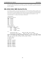
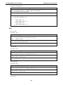
RS-232/422/485 Serial Ports
The UC-8430-CE computer comes with 8 high performance serial ports named from “COM3” to “COM10”. All of
them are designed to provide reliability, high-speed and 3-in-1 (i.e., RS-232, RS-422, and RS-485) operation
mode switch for your diverse applications. Each of these ports supports baudrate settings up to 921600 bps.
You can use the interface utility setinterface.exe to change or display your port interface. Ex.: Type
“setinterface COM3: 1” to change the port interface to RS-485 2W.
\>setinterface
ModelName:UC-8430-CE
COM3: = RS-232
COM4: = RS-232
COM5: = RS-232
COM6: = RS-232
COM7: = RS-232
COM8: = RS-232
COM9: = RS-232
COM10: = RS-232
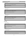
\> setinterface –h
SetInterface [COMx:] [mode]
mode:
0 (RS232)
mode:
1 (RS485 2 Wire)
mode:
2 (RS422)
mode:
3 (RS485 4 Wire)
e.g.
SetInterface COM5: 2
Change the COM5: mode to RS422
SetInterface $device\COM10 3
Change the COM10: mode to RS485 4wire
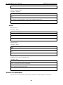
You can either enable or disable the FIFO by the utility , “setfifo”. Ex.: Type “setfifo
COM3: 0” to disable FIFO of COM3. or type “setfifo COM3: 1” to enable FIFO of COM3
After that, you can check the FIFO status by type “setfifo”
\> setfifo COM3: 0
Set FIFO success
\> setfifo
COM3 FIFO = Disabled
COM4 FIFO = Enabled
COM5 FIFO = Enabled
COM6 FIFO = Enabled
COM7 FIFO = Enabled
COM8 FIFO = Enabled
COM9 FIFO = Enabled
COM10 FIFO = Enabled
1-6
2
2.
Getting Started
In this chapter, we explain how to operate an UC-8430-CE computer from a PC. The PC will be referred to as
a development workstation and the UC-8430-CE computer will be called the target computer.
We describe the steps needed for some operations, such as setting the system time, troubleshooting network
connectivity, etc. Some of these operations can be done using system commands after gaining access to the
computer, and others can be done with a web-based management system, as described in a later chapter.
The following topics are covered in this chapter:
Powering on the UC-8430
Resetting the UC-8430-CE Computer
Rebooting the UC-8430-CE Computer
Boot Loader
Operating the UC-8430-CE Computer via Serial Console
Changing the Network Settings
Virtual Private Network (VPN)
Operating the UC-8430-CE Computer via Telnet
User/Group Management
Adjusting the Time Zone
Adjusting the System Time
Starting and Stopping Services
Troubleshooting Network Connectivity
Simple Network Management Protocol (SNMP)
SNMP Agent
SNMP Manager
Accessing Files through File Sharing
UC-8430 WinCE User's Manual
Getting Started
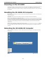
Powering on the UC-8430
To boot up the system, connect the power source to the power input located on the computer’s rear panel. It
takes about 5 seconds for the system to boot up. You will hear a clear “BEEP” sound when the boot up
procedure is finished. Once the system is ready, the “Ready” LED will light up and stay on until you shut down
the computer.
Resetting the UC-8430-CE Computer
Warm-Start: When powering on, push the “Reset” button briefly (for less than1 second). The computer will
reboot automatically.
Cold-Start: Switch the power off and then on again. The computer will reboot automatically.
Reset to Factory Defaults (Configuration only): If the computer is not working properly and you would like
to reset it to factory default settings, press and hold the “Reset” button for 5 seconds as the operating system
is starting up. The buzzer sounds while the factory default settings are being loaded. After the factory default
settings have finished loading, the computer will reboot automatically. Do not confuse this action with
“Warm-Start.”
Reset to Factory Defaults (Configuration and file system): If the computer will not start up, you must go
to the Boot Loader and format the flash storage. Once the flash storage has been reformatted, restart the
computer.
Rebooting the UC-8430-CE Computer
While the computer is powering on, click the “start” button and select “Reboot.” The computer will reboot
automatically.
2-2
UC-8430 WinCE User's Manual
Getting Started
Boot Loader
Three functions are provided to enhance the stability of the operating system.
•
Reset to default—This function allows users to load the factory default into the UC-8430.
•
Format storage flash—CE 6.0 is a FAT-based system. The system cannot work well when the FAT table is
•
Firmware upgrade—The latest firmware can be downloaded from Moxa’s website. See Appendix A for
crashed. This function allows users to format the file system and reboot UC-8430.
instructions on how to upgrade the firmware.
Use the following procedure to access the boot loader menu from the serial console:
1. Power off the UC-8430-CE.
2. Connect the serial console cable to your PC.
3. Go to [Start] [Programs] [Accessories] [Communication] [Terminal] to create a new
terminal. Use these settings: Baudrate = 115200, Hardware Flow Control = None, Data bits = 8, Parity =
None, Stop bits = 1, Terminal = VT100.
4. Activate this terminal window on your PC.
5. Hold down the “DEL” key.
6. Power on the UC-8430-CE.
Operating the UC-8430-CE Computer via Serial
Console
The serial console port gives users a convenient way of connecting the development workstation to the console
utility of the target computer. This method is particularly useful when using the target computer for the first
time.
After connecting the serial cable, return to the development workstation and start a terminal program (e.g.,
HyperTerminal). Use the following console port settings.
Baud rate
115200 bps
Parity
None
Data bits
8
Stop bits
1
Flow Control
None
Terminal
VT100
Next enter the login name and password. The default values are both admin.
Login: admin
Password: admin
Changing the Network Settings
The UC-8430-CE computer comes with three network interfaces. The default IP addresses and netmasks of the
network interfaces are as follows:
Default IP Address
Netmask
LAN 1
DHCP
DHCP
LAN 2
192.168.4.127
255.255.255.0
LAN3
192.168.4.127
255.255.255.0
There are two methods to change the network settings of the UC-8430: Use the network settings function of
the OS, or use the Serial Console connection.
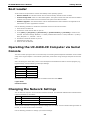
Use the following procedure to change your network settings.
2-3
UC-8430 WinCE User's Manual
Getting Started
1. Go to [Start] [Settings] [Network and Dial-Up Connections].
2. Right click the LAN icon and the click Property.
3. Click OK.
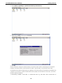
Another method to change the network setting is via Serial Console. Refer to “Operating the UC-8430-CE
Computer via Serial Console”, and connect the UC-8430. Type netconfig -h to get help on this utility.
To illustrate how to match the settings to your application, let’s assume that your development workstation has
a LAN port at 192.168.1.5, and the Domain Name Server (DNS) is at 192.168.2.6. In this case, you should
issue the following command:
\> netconfig –n LAN1 –i 192.168.1.5 –m 255.255.255.0 –g 192.168.1.254 –d 192.168.2.6
2-4
UC-8430 WinCE User's Manual
Getting Started
Use netconfig command without parameters to view the new settings:
\> netconfig
LAN1 Interface Configuration:
IP Address:
192.168.1.5
SubNet Mask:
255.255.255.0
Gateway:
192.168.1.254
DNS:
192.168.2.6
LAN2 Interface Configuration:
IP Address:
192.168.4.127
SubNet Mask:
255.255.255.0
Gateway:
DNS:
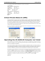
Virtual Private Network (VPN)
Windows Embedded CE supports Virtual Private Networks (VPNs). The VPN support in Windows Embedded CE
includes Layer Two Tunneling Protocol (L2TP), IP Security Protocol (IPSec), and Point-to-Point Tunneling
Protocol (PPTP). L2TP/IPSec enables enhanced security for Virtual Private Network (VPN) client connections
from Windows Embedded CE-based devices to corporate servers. PPTP is a Network protocol that adds a
security infrastructure for the transfer of data from a remote client to a private enterprise server, which creates
a VPN by using TCP/IP-based data networks.
Currently, this function is supported only by the UC-8430-CE. For VPN questions concerning the UC-8430-CE,
please contact Moxa’s Technical Support team.
Operating the UC-8430-CE Computer via Telnet
Before operating your UC-8430-CE computer using a Telnet client, we suggest that you change the network
settings of the computer (see an earlier section) so that at least one of the two network ports is on the same
LAN as your development workstation.
Use a cross-over Ethernet cable to connect your development workstation directly to the target computer, or
a straight-through Ethernet cable to connect the computer to a LAN hub or switch. Next, use the Telnet client
on your development workstation to connect to the Telnet console utility of the target computer. Once a
connection is established, type the login name and password as requested to log on to the computer.
After logging in via the console port or a Telnet client, several busybox commands are available to operate the
computer. Use HELP to display all of the commands, or type HELP [command name] to display extended
help for the selected command. Some of the commands, such as DATE and TIME are very useful for managing
the computer’s the system time. Other commands, such as DIR and MKDIR are good utilities for file
management. For example, to inspect the file structure of the root directory, simply type DIR.
\> dir /b
NORFlash
2-5
UC-8430 WinCE User's Manual
Getting Started
My Documents
Program Files
Temp
Windows
User/Group Management
User Group—You should assign specific services, such as ftp and Telnet, to defined user groups so that these
services are accessible only by the users within the permissible user group. Three user groups, namely ftpd,
telnetd, and httpd, are created by default for your convenience.
Adding a Group—Use the command useradd –g <groupName> to create a user group.
\> useradd –g yyyy
group yyyy has been added.
Deleting a Group—To remove a group, use the command userdel –g <groupName>.
\> userdel –g yyyy
group yyyy has been removed.
Adding a User—Use the command useradd <newUserID> to add a user for accessing the system. The
user’s password, by default, is the same as the user name.
\> useradd xxxx
user xxxx has been added.
In addition, you can permit this user to access a particular service by typing -g followed by the user group name
of the service, i.e., useradd –g <groupName> <newUserID>. For example,
\> useradd –g telnetd xxxx
user xxxx is existent
group telnetd is existent
user xxxx has been added to group yyyy
Deleting a User—Use the command userdel <userID> to delete a user from the system. User “admin”
CANNOT be deleted.
\> userdel xxxx
user xxxx has been deleted
You can also just remove a user from a user group by using the command userdel –g
<groupName> <newUserID>. For example,
\> userdel –g yyyy xxxx
user xxxx has been removed from group yyyy
Changing the Password—Please use “System Manager” to change the Password.
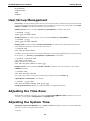
Adjusting the Time Zone
Windows CE 6.0 supports Time Zone. You can use [Control Panel][Date/Time] to adjunct your current
Time Zone. It also supports Daylight Date and Daylight Time.
Adjusting the System Time
Setting the System Time Manually—Use the date and time commands to query the current system date
and time or to set a new system date and time.
\> date
2-6
UC-8430 WinCE User's Manual
Getting Started
The current date is: Tuesday, November 22, 2005
Enter the new date (mm-dd-[yy]yy): 12-23-05
\> date /T
Wednesday, November 23, 2005
\> time
The current time is: 5:27:17 PM
Enter the new time (hh:mm:ss): 16:02:00
\> time /T
4:02:04 PM
The Date/Time setting is saved to UC-8430-CE RTC so that the date and time will not change when the system
reboots.
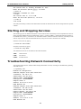
Starting and Stopping Services
After booting up, the UC-8430-CE computer runs several services continuously to serve requests from users or
other programs. Notable services include telnet (“TEL0:”), console (“CON0:”), world wide web HTTP (“HTP0:”),
file transfer FTP (“FTP0:”), and others. You will seldom need to use these services. However, note that you can
start or stop a service with its associated name by using the “services” command. For example,
Start the FTP service by typing:
\> services start FTP0:
Stop the FTP service by typing
\> services stop FTP0:
The default services for the UC-8430-CE are listed as below:
TEL0:
Telnet Service
FTP0:
FTP Service
CON0:
Console Service
Troubleshooting Network Connectivity
The ipconfig tool prints the TCP/IP-related configuration data of a host, including the IP addresses, gateway,
and DNS servers.
\> ipconfig /all
Windows IP configuration
Ethernet adapter Local Area Connection:
IP Address: 192.168.4.127
Subnet Mask: 255.255.255.0
Adapter Name: IXP425ETHNPE2
Description: IXP425ETHNPE2
Adapter Index: 2
Address: 80 86 33 33 34 12
DHCP Enabled: NO
Ethernet adapter Local Area Connection:
IP Address: 192.168.14.202
Subnet Mask: 255.255.248.0
Default Gateway: 192.168.15.254
Adapter Name: IXP425ETHNPE1
Description: IXP425ETHNPE1
Adapter Index: 3
Address: 78 56 34 91 cc dd
DHCP Enabled: NO
2-7
UC-8430 WinCE User's Manual
Getting Started
Host name: UC-8430-CE
Domain Name:
DNS Servers: 192.168.1.6
NODETYPE: 8
Routing Enabled: NO
Proxy Enabled: NO
Use the ping command to troubleshoot network connectivity, reachability, and name resolution. The command
verifies IP-level connectivity to another TCP/IP computer by sending Internet Control Message Protocol (ICMP)
Echo Request messages. The corresponding return Echo Reply messages are displayed, along with round-trip
times. For more information, type ping without parameters.
\> ping www.moxa.com
Pinging Host www.moxa.com [192.168.1.16]
Reply from 192.168.1.16: Echo size=32 time<1ms TTL=126
Reply from 192.168.1.16: Echo size=32 time<1ms TTL=126
Reply from 192.168.1.16: Echo size=32 time<1ms TTL=126
The route utility allows you to view or modify network routing tables. Type this command without parameters
to view a list of functions.
\> route
To view current routing items in the tables, type
\> route PRINT
To add a routing item on network interface 1, type
\> route ADD 192.168.0.0 MASK 255.255.0.0 192.168.15.254 IF 2
To delete a routing item, type
\> route DELETE 192.168.0.0
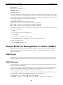
Simple Network Management Protocol (SNMP)
SNMP is the Internet Standard protocol for network management, and is part of the TCP/IP protocol suite.
SNMP was developed to monitor and manage networks. It uses a distributed architecture that consists of
agents and managers:
SNMP Agent
The SNMP agent is an SNMP application that monitors network traffic and responds to queries from SNMP
manager applications. The agent also notifies the manager by sending a trap when significant events occur.
SNMP Manager
An SNMP manager is an SNMP application that generates queries to SNMP-agent applications and receives
traps from SNMP-agent applications.
The UC-8430-CE computer installs an SNMP agent to serve as an SNMP device. You should install the SNMP
manager on the workstation computer (for example, a Linux system) that monitors the network. After
installing the nodes, you need to configure the SNMP manager and agent.
To check SNMP agent capabilities on a target UC-8430-CE (e.g, network IP at 192.168.3.127) computer, log on
to the workstation computer that the SNMP manager resides on and then type:
\> snmpwalk -v 2c -c public 192.168.3.127 system
SNMPv2-MIB::sysDescr.0 = STRING: Microsoft Windows CE Version 6.0 (Build 0)
2-8
UC-8430 WinCE User's Manual
Getting Started
SNMPv2-MIB::sysObjectID.0 = OID: SNMPv2-SMI::enterprises.8691.13.8430
DISMAN-EVENT-MIB::sysUpTimeInstance = Timeticks: (586211) 1:37:42.11
SNMPv2-MIB::sysContact.0 = STRING: Your System Contact Here
SNMPv2-MIB::sysName.0 = STRING: UC-8430-CE
SNMPv2-MIB::sysLocation.0 = STRING: Your Location Here
SNMPv2-MIB::sysServices.0 = INTEGER: 72
SNMPv2-MIB::sysORLastChange.0 = Timeticks: (0) 0:00:00.00
SNMPv2-MIB::sysORID.1 = OID: SNMPv2-MIB::snmp
SNMPv2-MIB::sysORID.2 = OID: UDP-MIB::udp
SNMPv2-MIB::sysORID.3 = OID: TCP-MIB::tcp
SNMPv2-MIB::sysORID.4 = OID: IP-MIB::icmp
SNMPv2-MIB::sysORID.5 = OID: IP-MIB::ip
SNMPv2-MIB::sysORID.6 = OID: RFC1213-MIB::at
SNMPv2-MIB::sysORID.7 = OID: IF-MIB::interfaces
SNMPv2-MIB::sysORID.8 = OID: SNMPv2-MIB::system
SNMPv2-MIB::sysORID.9 = OID: HOST-RESOURCES-MIB::host
SNMPv2-MIB::sysORDescr.1 = STRING: Sample SysOR Description ...
SNMPv2-MIB::sysORDescr.2 = STRING: Sample SysOR Description ...
SNMPv2-MIB::sysORDescr.3 = STRING: Sample SysOR Description ...
SNMPv2-MIB::sysORDescr.4 = STRING: Sample SysOR Description ...
SNMPv2-MIB::sysORDescr.5 = STRING: Sample SysOR Description ...
SNMPv2-MIB::sysORDescr.6 = STRING: Sample SysOR Description ...
SNMPv2-MIB::sysORDescr.7 = STRING: Sample SysOR Description ...
SNMPv2-MIB::sysORDescr.8 = STRING: Sample SysOR Description ...
SNMPv2-MIB::sysORDescr.9 = STRING: Sample SysOR Description ...
SNMPv2-MIB::sysORUpTime.1 = Timeticks: (20936) 0:03:29.36
SNMPv2-MIB::sysORUpTime.2 = Timeticks: (20936) 0:03:29.36
SNMPv2-MIB::sysORUpTime.3 = Timeticks: (20936) 0:03:29.36
SNMPv2-MIB::sysORUpTime.4 = Timeticks: (20936) 0:03:29.36
SNMPv2-MIB::sysORUpTime.5 = Timeticks: (20936) 0:03:29.36
SNMPv2-MIB::sysORUpTime.6 = Timeticks: (20936) 0:03:29.36
SNMPv2-MIB::sysORUpTime.7 = Timeticks: (20936) 0:03:29.36
SNMPv2-MIB::sysORUpTime.8 = Timeticks: (20936) 0:03:29.36
SNMPv2-MIB::sysORUpTime.9 = Timeticks: (20940) 0:03:29.40
You will see a series of messages from the SNMP agent on the UC-8430-CE computer. From there, you can
monitor and manage the computer.
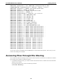
Accessing Files through File Sharing
The UC-8430-CE offers file sharing function so that remote computer can access the UC-8430-CE to read the
files. Follow the next steps to enable file sharing.
1. To enable file sharing function, you need to rename the hostname of the UC-8430-CE to avoid hostname
collision on the network.
In the Serial Console screen, enter the following command:
\>hostname Embedded_1
2-9
UC-8430 WinCE User's Manual
Getting Started
Now you have successfully changed the hostname to Embedded_1. You may use other hostname as you
wish.
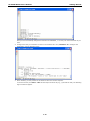
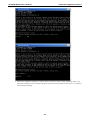
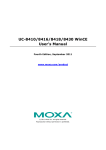
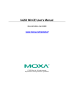
2. Configure the files you would like to share in the UC-8430-CE. Use \>netshare –h to configure the
parameters. See the following figure.
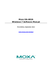
3. When finished, you may access the UC-8430-CE from the remote computer.
To use the function, click Start → Run and then input the device IP (e.g., \\192.168.30.199). The following
login window will appear.
2-10
UC-8430 WinCE User's Manual
Getting Started
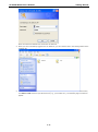
Enter Username and Password to access the UC-8430-CE.
4. When you have successfully logged in the UC-8430-CE, you can view the files in the sharing folders of the
UC-8430-CE.
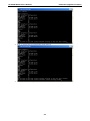
5. A file server function is available for transferring files to the UC-8430-CE efficiently. To use the function,
click Start Run and then input the device IP (e.g., \\192.168.100.1). The following login window will
appear.
2-11
UC-8430 WinCE User's Manual
Getting Started
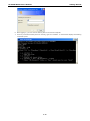
6. After logging in, you can view the sharing files on the remote computer.
7. From any command window (telnet or console), type the “netshare -h” command to display the following
command syntax:
2-12
3
3.
Management Tools
The UC-8430-CE ready-to-run embedded computers are network-centric platforms designed to serve as
front-ends for data acquisition and industrial control applications. Due to the distributed characteristics of the
devices that these computers control, they are often located in remote locations separate from the system
administrator. Managing this kind of remote computer requires handling configuration, file management, and
process (thread) monitoring/control over the network.
The UC-8430-CE computer comes with a pre-installed management system to assist administrators. Before
using the system, make sure that a CRT or LCD monitor is connected to your UC-8430-CE embedded computer,
and then double-click the desktop icon [System Manager].
The following topics are covered in this chapter:
System Information
Serial Port Configuration
Process (Thread) Monitoring/Control
Services Monitoring/Control
Display
User/Group Management
Auto Launch Configuration
Web Server Configuration
UC-8430 WinCE User's Manual
Management Tools
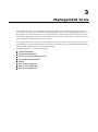
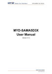
System Information
The first page displays the system information of the UC-8430-CE computer, including the firmware version of
the computer, .Net CF version, the system time, and system resources, including main memory and file system
usage.
Serial Port Configuration
The UC-8430-CE has 8 high-performance serial ports. When the system starts, specify the default operation
mode (RS-232, RS-422, or RS-485). The factory default mode is RS-232.
Click the COM Ports tab to see the status of the 4 ports.
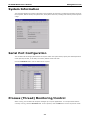
Process (Thread) Monitoring/Control
While running, the UC-8430-CE computer manages up to 32,000 applications. To view processes that are
currently running, click the Processes tab. To kill a process, click the kill button next to the process name.
3-2
UC-8430 WinCE User's Manual
Management Tools
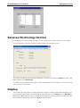
Services Monitoring/Control
Some services, such as FTP, Telnet and HTTP, run in the background to provide service for user requests.
Click the appropriate check box to enable or disable operation of a particular service.
You can also use SNTP to adjust the time automatically. To do this, check mark the Enable check box under
SNTP, and then click Save Settings.
To maintain normal operation of the computer, some listed services cannot be stopped. Such services do not
have a check box next to them.
Display
The UC-8430-CE’s VGA output uses a DB15 female CRT connector to display the Windows CE desktop on an
LCD monitor or a CRT monitor. The default settings, which are shown on the Display tab, are 800*600 for
Width*Height, 60 (in Hz) for Frequency, and 16 (bits) for Depth. For general use, adjust the settings to match
the specifications of your LCD or CRT. Click Apply to save the setting.
3-3
UC-8430 WinCE User's Manual
Management Tools
Note: You must reboot your UC-8430-CE for new settings to take effect.
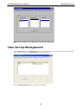
User/Group Management
Use the Add button on the User/Group tab to assign specific services (such as ftp and telnet) to individual
users and user groups. Use the Remove button to remove users.
Use the Change Password utility to change the password.
3-4
UC-8430 WinCE User's Manual
Management Tools
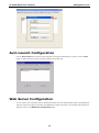
Auto Launch Configuration
Use the Auto Launch tab to specify which programs will execute automatically on boot up. Click the Add
button to add programs to the list, and then restart the UC-8430-CE.
Web Server Configuration
You will need to use a Windows 2000 or Windows XP machine for web administration. Open Internet Explorer
and then type the URL http://192.168.3.127/WebAdmin (replace the IP with your UC-8430-CE’s network IP
address) to link to the Web Server Configuration page.
3-5
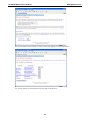
UC-8430 WinCE User's Manual
Management Tools
You can now create a new web site or create a virtual web path for your web application.
You can also change the authentication for each web virtual directory.
3-6
UC-8430 WinCE User's Manual
Management Tools
3-7
4
4.
Web-based Management System
Note: Internet Explorer 5.5 and above is required to use the web based management system.
The UC-8430-CE ready-to-run embedded computers are network-centric platforms and are designed to serve
as excellent front-ends for data acquisition and industrial control. Due to the distributed characteristics of the
devices, that these computers control, they often reside in harsh areas as the devices themselves and are away
from system administrators. To manage these computers, operations such as networking/server configuration,
file management, and process (thread) monitoring/control become a critical area to consider.
To resolve these management issues and accordingly reduce the toil of system administration, a web-based
management system is installed into the UC-8430-CE computer. This system incorporates often-used features
into CGI pages and categorizes them on a menu bar.
Before operating the system, please make sure you have a network connection from your PC to the target
computer and can open an Internet browser at your PC after the connection. Then, use the IP address of the
target computer as a home page URL. After the main page comes out, click on Web-Based Management.
Provide your authentication data including user ID and password into the corresponding fields of the prompt
(case sensitive) and then hit the enter key to request access to the management system. The system checks
your data with the users previously defined in the computer and then determines the validity of your logon.
The default User ID and Password are as follows:
User ID: admin
Password: admin
The following topics are covered in this chapter:
System Information
Networking/Server Configuration
Serial Port Configuration
Process (Thread) Monitoring/Control
Launching Processes Automatically
Services Monitoring/Control
Binary/Text File Management
UC-8430 WinCE User's Manual
Web-based Management System
System Information
After you logon successfully, the main page displays the system information of the target UC-8430-CE
computer, including the firmware version of the computer, the RTC time, the CPU system time, and system
resources including main memory and file system usage (RAM and Flash).
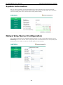
Networking/Server Configuration
The UC-8430-CE computer has 3 embedded network interfaces. To view or change their settings, click the
Networking item on the menu bar. After the page loads, enter the relevant details on the corresponding text
fields and then click “Update” to make the changes effective for the interfaces.
4-2
UC-8430 WinCE User's Manual
Web-based Management System
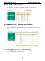
Serial Port Configuration
The UC-8430-CE contains 8 x MU860 high-performance serial ports. When the system starts up you can specify
the default operation mode (RS-232, RS-422 or RS-485). The default mode would be RS-232.
Process (Thread) Monitoring/Control
At runtime, the UC-8430-CE computer manages up to 32 applications. You can use the management system to
monitor and control them. To view current processes, please click the Processes item on the main menu bar.
The running processes are then displayed. You can kill a process by clicking the “kill” button next to the process
name.
Launching Processes Automatically
To have your application start on boot, do the following:
Step 1: Click the “Processes” item on the main menu bar. At the lower part of the page, there is an area
marked as “Automatic Launching”.
4-3
UC-8430 WinCE User's Manual
Web-based Management System
Step 2: Fill in the full path of the application in the first text field and its arguments in a separate text field if
there are any.
Step 3: Click “Add”.
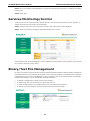
Services Monitoring/Control
Some services run on the background to provide services, such as ftp, telnet and etc, for user requests. To
monitor and control these services, do the following:
Step 1: Click the “Services” item on the main menu bar. The running services are displayed.
Step 2: Click on a check box to toggle a start/stop operation for a service.
Some listed services cannot be stopped in order to maintain normal operation of the computer. Such services
do not have a check box next to them.
Binary/Text File Management
On a PC, it is certainly convenient to have a friendly window-based file manager to browse, delete, and organize
files and directories. On the UC-8430-CE computer, such a convenient feature is simulated by the web-based
management system. Just click “File Manager” to view the directory tree of your target UC-8430-CE computer.
Using the File manager, you can perform the following operations:
•
To browse a child directory, click the name of the directory.
•
To delete a file, click the icon with an X in front of the file icon.
•
To create a child directory, click Create Directory and then follow the instructions.
•
To refresh the current directory, click Current Directory at the top of the page.
4-4
UC-8430 WinCE User's Manual
Web-based Management System
In addition, the management system offers a mechanism for file upload. This mechanism helps you transfer
files from your workstation to the target computer in an easy way. For instance, after you have built an
application on the development workstation, you can use this mechanism to upload the application to the
current directory of the target computer.
Step 1: Click “Upload File”. A browser window pops up.
Step 2: From the pop-up browser window, click “Browse” to bring up a local file manager.
Step 3: Browse to and select the file that you want to upload and click “open”.
Step 4: Navigate back to the “File Upload” browser window, and click “OK”. The file uploading will start.
Step 5: After the file is uploaded completely, refresh the page.
4-5
A
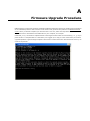
A.
Firmware Upgrade Procedure
MOXA engineers continuously enhance and develop software features to improve the quality and functionalities
of the embedded products. New firmware will be continuously produced and posted in the MOXA download
center. When you decide to replace your firmware with a new one, follow the steps below. Go to MOXA
download center to download an executable file for your computer, for example
UC8430CE_V1.0_10071418.exe. Upload this file to the target machine under the root directory (i.e., \). If you
place this file in a compact flash or a USB device, we suggest you to copy it to the root directory for a faster
upgrade operation. Logon the target computer via a telnet or console connection. Execute this file. Press “y” to
continue the process.
UC-8430 WinCE User's Manual
Firmware Upgrade Procedure
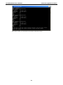
1. Wait for the upgrade to complete; it will take about 5 minutes to finish it. After upgrading, select if you
would like to keep the current network settings or restore the factory default values. Press “Y” to keep the
current network settings.
A-2
UC-8430 WinCE User's Manual
Firmware Upgrade Procedure
2. Press “Y” to keep the current automatic launch settings.
3. Press “Y” to reboot the target UC-8430-CE.
A-3
UC-8430 WinCE User's Manual
Firmware Upgrade Procedure
After system restart, you will find the new firmware ready and running.
A-4
B
B.
Application Development
To let user’s programs work with the device easily and quickly. The “mxdev” library on C++ and the “mxdevice”
library on C Sharp is provided to help users develop their application on UC-8430-CE device. The complete
source code can be found in the example directory in software CD.
The following topics are covered in this appendix:
UC-8430-CE SDK and Library
Install SDK
Developing an application with VS2005
Visual C++ Library
Visual C++ Examples
Net Compact Framework Library
Visual C# Examples
UC-8430 WinCE User's Manual
Application Development
UC-8430-CE SDK and Library
Install SDK
UC-8430-CE provides a programming library for simplify your development time.
Before using the Library SDK, you must install the MOXA UC-8430-CE SDK (UC-8430-CE.msi). The SDK file is
in the “sdk” directory of UC-8430-CE Software CD. The following steps are the SDK installation guide.
•
Copy UC-8430-CE.msi to your development PC (Windows XP/Vista)
•
Double click the UC-8430-CE.msi.
•
Follow the wizard prompt to complete the installation steps.
Developing an application with VS2005
•
Open Microsoft® Visual Studio .Net 2005.
•
From the File menu, choose New Project.
•
Choose the Project Type and then select the Smart Device Application as the type of project.
•
Fill in the project name and click OK.
•
Choose Windows CE as the target platform.
•
Select the desired project type and click OK.
•
Write your application code.
•
From the toolbar, choose the Device SDK UC-8430-CE.
•
From the Build menu, choose Build Project or Rebuild Project.
•
When you complete your application, upload it to the embedded computer.
•
Log on to the embedded computer. At the console prompt, execute it directly if it is a C++ or C# file
Visual C++ Library
After the SDK is installed on your development PC, the library can be found in your Visual Studio 2005/2008
environment.
UART
This function opens a serial port.
unsigned int mxsp_open(int port);
Inputs:
<port>
Port number (starting from 3).
Return Values:
When successful, this function returns the handle of the open port.
When an error occurs, it returns a negative value.
Remark:
For example, uses mxsp_open(3) to retrieve the interface of COM3:
The function is equivalent Win32 CreateFile() API.
This function closes a serial port.
int mxsp_close(unsigned int fd);
Inputs:
<fd> Handle of the open port.
Return Values:
When successful, this function returns 0. When an error occurs, it returns a negative value.
Remark:
B-2
UC-8430 WinCE User's Manual
Application Development
The function is equivalent Win32 CloseHandle() API.
This function sets the type of communication interface for a serial port.
int mxsp_set_interface(unsigned int fd, int mode);
Inputs:
<fd> Handle of the open port.
<mode> 0: RS232, 1: RS485_2WIRE, 2: RS422, 3: RS485_4WIRE
Return Values:
When successful, this function returns 0.
Remark:
This function gets the type of communication interface of a serial port.
int mxsp_get_interface(unsigned int fd);
Inputs:
<fd> Handle of the open port.
Return Values:
When successful, this function returns one of the values from 0 to 3.
The function returns a negative value when an error occurs.
Remark:
DIO
This function opens an access to the DIO device.
HANDLE mxdgio_open(void);
Inputs:
None
Return Values:
When successful, this function returns an access to the DIO device. Otherwise, there is an error.
Remark:
This function closes the access to the DIO device.
void mxdgio_close(HANDLE fd);
Inputs:
<fd>
The access to the device.
Return Values:
none
Remark:
This function gets the signal state of a digital input channel.
int mxdgio_get_input_signal(HANDLE fd, int port);
Inputs:
<fd>
The access to the device.
<port>
the port index, from 0 to 3 mapping to DI0~DI3
Return Values:
Returns 1 for a high signal or 0 for a low signal, if successful. Otherwise, it returns a value of -1.
Remark:
This function gets the signal state of a digital output channel.
B-3
UC-8430 WinCE User's Manual
Application Development
int mxdgio_get_output_signal(HANDLE fd, int port);
Inputs:
<fd>
The access to the device.
<port>
the port index, from 0 to 3 mapping to DO0~DO3
Return Values:
Returns 1 for a high signal or 0 for a low signal, if successful. Otherwise, it returns a value of -1.
Remark:
This function sets a high signal to a digital output channel.
int mxdgio_set_output_signal_high(HANDLE fd, int port);
Inputs:
<fd>
The access to the device.
<port>
the port index, from 0 to 3 mapping to DO0~DO3
Return Values:
When successful, this function returns 0. When an error occurs, it returns -1.
Remark:
This function sets a low signal to a digital output.
int mxdgio_set_output_signal_low(HANDLE fd, int port);
Inputs:
<fd>
The access to the device.
<port>
the port index, from 0 to 3 mapping to DO0~DO3
Return Values:
When successful, this function returns 0. When an error occurs, it returns -1.
Remark:
Watchdog
This function starts a watchdog timer.
int mxwdg_open(unsigned long time);
Inputs:
<time> Specifies an exact time period in milliseconds. Note that the watchdog timer needs to be
refreshed to avoid reset.
Return Values:
When successful, this function returns a positive value representing a file descriptor. Otherwise, it returns a
negative value.
Remark:
After calling the mxwdg_open (), you must call mxwdg_refresh () in the specified time<time> or the system
will be triggered rebooting.
This function refreshes the watchdog timer, and should be called periodically during timer timeouts.
int mxwdg_refresh(int fd);
Inputs:
<fd> Specifies the file descriptor of the watchdog timer.
Return Values:
When successful, this function returns 0. Otherwise, it returns a negative value.
Remark:
B-4
UC-8430 WinCE User's Manual
Application Development
This function stops the watchdog timer.
void mxwdg_close(int fd);
Inputs:
<fd> Specifies the file descriptor of the watchdog timer.
Return Values:
none
Remark:
Buzzer
This function opens a handle that operates the buzzer.
HANDLE mxbuzzer_open(void);
Inputs:
none
Return Values:
When successful, this function returns a positive value (or handle) that represents the buzzer device.
Remark:
This function regulates the buzzer.
void mxbuzzer_beep(HANDLE fd, int time);
Inputs:
<fd>
Specifies the open handle of the buzzer.
<time> Specifies the amount of time (in milliseconds) that the beep lasts.
Return Values:
none
Remark:
This function closes the open handle of the buzzer.
void mxbuzzer_close(HANDLE fd);
Inputs:
<fd>
Specifies the open handle of the buzzer.
Return Values:
none
Remark:
Visual C++ Examples
In the software CD, you can get the C++ examples for your reference.
Net Compact Framework Library
For .Net programming, MOXA also provides .Net Compact Framework library.
UART
set the interface of UART.
B-5
UC-8430 WinCE User's Manual
Application Development
Class Name: SerialInterface
Method: void SetComPortInterface(string port, SerialMode mode);
Inputs:
<port> serial port name string,
e.g. COM3:, COM4:, $device\COM12
<mode> the interface number of serial port
Return Values:
none
Remark:
public enum SerialMode : byte
{
RS232_MODE = 0x0,
RS485_2WIRE_MODE = 0x1,
RS422_MODE = 0x2,
RS485_4WIRE_MODE = 0x3
}
DIO
Open the DIO
Class Name: DIO
Method: bool Open();
Inputs:
<port>
the port index, from 0 to 3 mapping to DO0~DO3
<data>
1 : HIGH, 0 : LOW
Return Values:
true on success, false, the function fails
Remark:
Close the DIO
Class Name: DIO
Method: void Close();
Inputs:
<port>
the port index, from 0 to 3 mapping to DI0~DI3
Return Values:
1 indicates HIGH, 0 indicates LOW
Remark:
get the DI value
Class Name: DIO
Method: int GetInputSignal(int port);
Inputs:
<port>
the port index, from 0 to 3 mapping to DI0~DI3
Return Values:
1 indicates HIGH, 0 indicates LOW
Remark:
get DO value
B-6
UC-8430 WinCE User's Manual
Application Development
Class Name: DIO
Method: int GetOutputSignal(int port);
Inputs:
<port>
the port index, from 0 to 3 mapping to DO0~DO3
Return Values:
1 indicates HIGH, 0 indicates LOW
Remark:
Set the DO value to High
Class Name: DIO
Method: bool SetOutputHigh(int port);
Inputs:
<port>
the port index, from 0 to 3 mapping to DO0~DO3
Return Values:
true indicates success, otherwise the function fails
Remark:
Set the DO value to Low
Class Name: DIO
Method: bool SetOutputLow(int port);
Inputs:
<port>
the port index, from 0 to 3 mapping to DO0~DO3
Return Values:
true indicates success, otherwise the function fails
Remark:
Watchdog
startup a watchdog
Class Name: Watchdog
Method: bool Open(int nTime);
Inputs:
<time> the watchdog refresh time interval in milliseconds.
Return Values:
True on success, false indicates failure.
Remark:
After calling the open(), you must call refresh() in the specified time(nTime) or the system will be triggered
rebooting.
The watchdog refresh function call.
Class Name: Watchdog
Method: bool refresh();
Inputs:
none
Return Values:
true indicates the watchdog refresh succeed, false indicates refresh failure.
B-7
UC-8430 WinCE User's Manual
Application Development
Remark:
close the watchdog handle
Class Name: Watchdog
Method: bool close();
Inputs:
none
Return Values:
true indicates the watchdog refresh succeed, false indicates refresh failure.
Remark:
Buzzer
Open the buzzer
Class Name: Buzzer
Method: bool Open();
Inputs:
none
Return Values:
none
Remark:
Close the buzzer
Class Name: Buzzer
Method: void Close();
Inputs:
none
Return Values:
none
Remark:
Enable the buzzer voice for a specified time.
Class Name: DIO
Method: bool Beep(int time);
Inputs:
<time>
the “beep” voice time in milliseconds.
Return Values:
true on success, false, the function fails
Remark:
Visual C# Examples
A device .Net CF 3.5 class library (mxdevice.dll) is provided to simplify application development
B-8
UC-8430 WinCE User's Manual
Application Development
with Visual Studio 2005 tools. This library covers the .Net CF Class Library for the buzzer, and digital I/O
devices. To link the library with your Visual Studio 2005 project environment, perform the following steps from
your Visual Studio 2005 tool:
1. Copy the library file mxdevice.dll to any folder on your local disk.
2. This file can be found on the product CD in the folder \sdk\dot Net Compact Framework Library, or the file
can be downloaded from the FTP site listed in the NOTE at the bottom of this page.
3. Open the Visual Studio 2005 IDE tool, and then add a new C# Smart device console application.
4. Enter the project name and location path.
5. In the Solution Explorer View, add mxdevice.dll to the reference section.
6. Click OK.
NOTE: You may need to copy the “mxdevice.dll” within the example when you try to execute the
program.
B-9