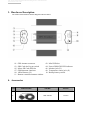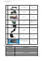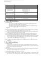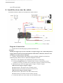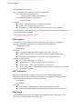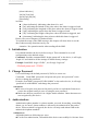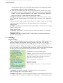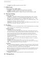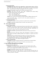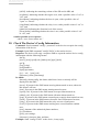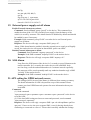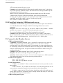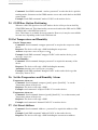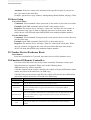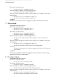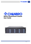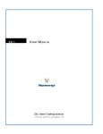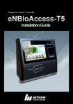
1
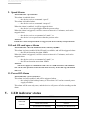
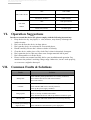
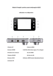
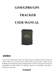
The professional Global GPS Tracking device manufacturers.
WWW.RXTCOM.COM
GSM/GPRS/GPS
Vehicle Tracker Device
User Manual
Preface
Thank you for purchasing our GPS tracker device. This
manual shows how to use the product smoothly and correctly.
Before using the product, please read this manual carefully.
Please note that specification and information are subject to
changes without prior notice in this manual. Any change will
be integrated in the latest release. The manufacturer assumes
no responsibility for any error or omission in this manual.
The professional Global GPS Tracking device manufacturers.
WWW.RXTCOM.COM
Content
I. Function Introduction ........................................................................................................................................................... 3
1. Main Features .............................................................................................................................................................. 3
2. Applications ................................................................................................................................................................. 3
4. Accessories ................................................................................................................................................................... 4
5. Specifications ............................................................................................................................................................... 5
6. SIM CARD Installations ................................................................................................................................................ 6
7. SD CARD Installations .................................................................................................................................................. 6
8. Install the device into the vehicle................................................................................................................................ 7
9. Turn on the Tracker Device .......................................................................................................................................... 8
II. Tracker Device Operating Mode .......................................................................................................................................... 8
1. SMS Monitoring Mode................................................................................................................................................. 8
2. GPRS Tracking Mode .................................................................................................................................................... 8
3. Without SIM Card, GPS Device Track Record Mode ................................................................................................... 9
III. Basic functions ..................................................................................................................................................................... 9
1. Initialization ............................................................................................................................................................... 11
2. Change Password ....................................................................................................................................................... 11
3. Authorization: ............................................................................................................................................................ 11
4. Locating: ..................................................................................................................................................................... 12
5. Real Time Voice Monitoring ...................................................................................................................................... 13
6. Offline Voice Recording: ............................................................................................................................................ 13
7. IMEI Check: ................................................................................................................................................................ 14
8. Timezone Setting: ...................................................................................................................................................... 14
9. Geo-fence: .................................................................................................................................................................. 14
10. Moving Alarm ............................................................................................................................................................ 14
11. Overspeed Alarm ....................................................................................................................................................... 15
12. Cut off the Oil and Power System ............................................................................................................................. 15
13. Resume the Oil and Power System ........................................................................................................................... 16
14. Arming ........................................................................................................................................................................ 16
15. Shacking Alarm .......................................................................................................................................................... 16
16. Tracking Trace Recording ........................................................................................................................................... 17
17. Check the Device’s Working Status ........................................................................................................................... 17
18. Check The Device’s Config Information ..................................................................................................................... 18
19. External power supply cut off alarm ......................................................................................................................... 19
20. SOS Alarm .................................................................................................................................................................. 19
21. APN setting for GPRS network access ....................................................................................................................... 19
22. IP and Port Setup for GPRS network access .............................................................................................................. 20
23. Connect to the Monitor Server .................................................................................................................................. 20
24. GSM Base Station Positioning ................................................................................................................................... 21
25. Get Temperature and Humidity ................................................................................................................................ 21
26. Set the Temperature and Humidity Alarm ................................................................................................................ 21
27. Get Street Address ..................................................................................................................................................... 21
28. Siren Setup ................................................................................................................................................................. 22
29. Tracker Device Hardware Reset: ............................................................................................................................... 22
30. Function Of Remote Controller: ................................................................................................................................ 22
IV. Alarms ................................................................................................................................................................................ 23
1. Lower Power Alarm ................................................................................................................................................... 23
2. External power supply cut off alarm ......................................................................................................................... 23
3. SOS ............................................................................................................................................................................. 24
4. Door Alarm ................................................................................................................................................................. 24
5. Shock Sensor alarm .................................................................................................................................................... 24
6. ACC alarm ................................................................................................................................................................... 24
7. Move alarm ................................................................................................................................................................ 25
8. Geo-fence alarm ........................................................................................................................................................ 25
9. Speed Alarm ............................................................................................................................................................... 26
10. Lack SD card space Alarm .......................................................................................................................................... 26
11. Power Off Alarm ........................................................................................................................................................ 26
V. LED indicator status ........................................................................................................................................................... 26
VI. Operation Suggestions ........................................................................................................................................................ 27
VII.
Common Faults & Solutions ...................................................................................................................................... 27
The professional Global GPS Tracking device manufacturers.
WWW.RXTCOM.COM
I. Function Introduction
This tracker is a new product based on GSM/GPRS network and GPS
satellite positioning system. It has multiple functions, such as positioning,
tracking, monitoring and alarms for security. User can easily track and monitor
vehicles or other moving targets by mobile phone or Internet-connected
computer.
1. Main Features
1) Support A-GPS / GPS / base station positioning.
2) Support SMS/GPRS/Internet Network data transfer. (GPRS/Internet instructions
in CD enclosed)
3) Support point-to-point, point-to-group, group-to-group monitoring.
4) Support single positioning and continuous location tracking.
5) Support voice monitoring and recording. (SD card required)
6) Supports historical traveling locus uploading. (SD card required)
7) Support Vehicle Anti-theft alarming. (Remote control setup/Cancel)
8) Support electronic fence alarm, door open alarm, ACC alarm, moving alarm,
speeding alarm, SOS alarm and other kinds of emergency alarms.
9) Support alarm for equipment malicious removal.
10) Built-in vibration sensor; external temperature and humidity sensor be
supported.
2. Applications
This product is widely used for vehicle and other moving objects,
especially for personal cars, company/government vehicles, taxies and
motorcycles.
The professional Global GPS Tracking device manufacturers.
WWW.RXTCOM.COM
3. Hardware Description
The tracker device hardware interface diagram is shown as below:
01.
03.
05.
07.
09.
11.
GPS Antenna connector
SIM Card slot Pop-up switch
Micro SD Card (SD) slot
GSM Antenna connector
10Pin Harness (J2)
Remote controller antenna window
02.
04.
06.
08.
10.
Mini USB slot
Power/GSM/GPS LED indicator
Monitor jack (J3)
Temperature sensor jack (J1)
Backup battery switch
4. Accessories
NO
1
PHOTOES
NAME
NOTE
GPS Antenna
3 meters
The professional Global GPS Tracking device manufacturers.
WWW.RXTCOM.COM
2
GSM Antenna
3
Microphone
3 meters
1.5 meters
4
Harness
10PIN
5
Relay
12V/40A or 24V/40A
according to vehicles
6
Remote control
15 meters control
7
USB Cable
0.8 meters
8
Siren
Option
9
Temperature and humidity
sensor
Option
5. Specifications
Content
specifications
SIZE
83*54*26mm
Weight
120g
Network
GSM/GPRS
Locating Method
A-GPS/GPS/GPRS
GSM Band
850/900/1800/1900 MHz
GSM Sensitivity
-105dBm
The professional Global GPS Tracking device manufacturers.
WWW.RXTCOM.COM
GPS Module
UBLOX
GPS Sensitivity
-159dBm
GPS Accuracy
5m
GPS Start-up time
(Antenna opensky)
Cold start-up time: 27s
Warm start-up time: 27s
Hot start-up time: 1s
Voltage of power system
12 V -24V
Backup battery
Chargeable 3.7V 800mAh Li-ion battery
Storage Temp.
-40°C to +85°C
Operation Temp.
-20°C to +65°C
Humidity
5%--95% non-condensing
6. SIM CARD Installations
Installation Steps:
Use a tweezers or other sharp things to press the SIM CARD popup switch;
Take out the SIM card slot after it is popped up;
Put SIM card into the SIM card slot and insert it back to its original position
after confirming the SIM card at the right place.
Attentions:
Please don't insert, change or remove SIM card when the tracker device is working.
If you need to this, please confirm that the device is power off.
Please check SIM card and make sure that incoming calls display is available, call
transfer is forbidden and the PIN code is locked.
The SMS must be TXT format; The PDU format will not be supported by device.
Please ensure that GPRS function of your SIM card is available. The GSM base
station location and the communication between the tracking software/server and the
device need to be supported by GPRS function. (If your device only work in SMS
control mode, the GPRS function is unnecessary).
The device only supports GSM network. WCDMA or other 3G SIM cards are not
supported.
7. SD CARD Installations
Installation Steps:
Insert the SD card (Micro SD card) into the corresponding card slot in the correct
direction. If you need to remove the SD card from the device, just press the SD card
and it will be popped up automatically.
Attentions:
Please don't insert or remove the SD card when the device working. If you need do
this, please confirm that the device is power off.
Maximum capacity of SD card is up to 32GB;
In order to read the data in SD card, you can connect the device to the computer with
the USB cable. You can also remove the SD card when the device is power off, and
The professional Global GPS Tracking device manufacturers.
WWW.RXTCOM.COM
use a SD card reader.
8. Install the device into the vehicle
The hardware interface with the car/external harness is shown as below:
Diagram of connection:
1. Put the device into the proper position inside the car.
Attentions:
Identify the trigger type of your car (Positive or negative trigger). For vehicle with positive
trigger, Please keep the device isolated from the vehicle frame. Otherwise, the device and
the battery of your car may be damaged.
2. Find the 10 PIN harness and connect wires with the original car circuits as
following step. Please refer to connection diagram as below.
Reference to the diagram, the installation procedure as following:
a) Connect POWER&GND wire to car battery. The red wire is connected to positive
terminal of car battery; the black wire is connected to negative terminal of car battery.
b) Identify the type of the door trigger (positive trigger or negative trigger).
When the door trigger is negative trigger:
Harness Door+ pin connect to the car battery Power;
Harness Door- pin connects to the door control circuit;
When the door trigger is positive trigger:
Harness Door+ pin connect to the door control circuit;
Harness Door- pin connects to the car battery ground;
c) Connect the white wire to the vehicle Car ACC ignition switch.
The professional Global GPS Tracking device manufacturers.
WWW.RXTCOM.COM
d) Placed the automotive relay socket to the proper position inside the hood of the car; Find
the car’s original engine cable and cut it off. Connect the engine side of the original cable
to the thick red cable of the relay socket; Connect the oil pump side of the original cable
to the thick yellow cable of the relay socket.
Attentions:
The white thin cable of the relay socket should be connected to the car supply power and
we have connected the thin white cable to the red thick cable already. (For original vehicle
usage, that’s ok.)
We have connected the yellow cable of the 10 PIN harness to the automotive relay
already.
The joints must have good insulation protection.
e) Connect the orange wire to the siren you bought. (Siren is Option).
3. Put the Reset button and SOS button to the place where the driver could touch
conveniently.
4. Connect the GPS antenna and GSM antenna to the corresponding connectors;
Find appropriate places to fix the two antennas and make sure they receive
signals well. The GPS Antenna must be exposed to the air and have no metal
obstruction.
5. Insert the Temperature and humidity sensors plug into the jack (J1). (Sensor is
Option).
6. If you need read data in the SD card or update device firmware, connect the
USB cable to the mini-USB interface. (Please refer to the firmware instructions
in the CD.)
Attentions:
Please ask the qualified engineers to install the device.
Do not install the device when GSM/GPS signal is in poor condition.
Place the antennas in appropriate positions with good signals.
Prevent the device from water and dust.
9. Turn on the Tracker Device
Turn on the backup battery switch, then insert 10 PIN harness into the 10 PIN jack
(J2). The tracker device will work normally after 3~5 minutes.
II. Tracker Device Operating Mode
The device has two operating modes:
1. SMS Monitoring Mode
SMS monitoring mode is the device’s default monitoring mode. User could use the
authorized telephones as a master, control/monitor the device by sending SMS text
messages. We mainly discuss this mode in this manual.
2. GPRS Tracking Mode
With an Internet-connected computer, user could also use a professional PC software
The professional Global GPS Tracking device manufacturers.
WWW.RXTCOM.COM
or service platform to control/monitor the device. This mode is called the GPRS
monitoring mode. Before using this mode, some related internet parameters should
be set firstly through the SMS monitoring mode. How to use the GPRS tracking
mode is beyond the scope of this manual. We only introduce the related GPRS
parameter setting in the following chapters.
3. Without SIM Card, GPS Device Track Record Mode
If the tracker device is not install the SIM card.
a) Press the SOS button Three seconds. The device will work in automatic track
record mode:
In this work mode, the tracker device must be installed on the SD card. Please
ensure that there is enough store room in the SD card. The historical trajectory
file in KML format stored in the SD card, it can be played directly in Google
Earth Tools.
Attentions:
must install the SD Card.
b) Press the remote control button "A". Device will go into theft mode. Any alarm
will trigger the siren. (For example: ACC ignition, the door opened alarm,
vibration alarm)
Attentions:
Must install the siren to the tracker device.
III. Basic functions
(Attention:
:The “+” in all following commands means there is a blank space
here in the short message,
,please do not type a real “+” character on your cell
phone.)
)
SMS is an important communicating way between a user and a device. Users could
send SMS messages through authorized mobile phones to control and monitor
devices; Devices could also send messages to the user’s authorized mobile phones,
to reply to the user's instructions, report the relevant information of the vehicles, or
perform one alarm.
Four Types of SMS messages are supported in this device:
SMS Command, sent by the master to control the device or change some
configuration.
SMS Response, reported by the device as a synchronous response to a SMS
command.
SMS Notification, reported by the device as an asynchronous response to a
SMS command ;
SMS Alarm, reported by the device when detecting one alarm or several
alarms.
(Attention: The device will not give any response to an illegal SMS message.)
SMS Command
A SMS command is used by the user to do some control action or change some
The professional Global GPS Tracking device manufacturers.
WWW.RXTCOM.COM
configuration of the device.
The command has two common formats as following:
For a command with parameter(s):
[cmd]+[pswd]+[space]+[parameter(s)…]
for a command without a parameter:
[cmd]+[pswd]
in which:
[cmd]: indicating the name of the command, and
[pswd]: indicating the password, and
[parameter(s)]: indicating the parameter(s) taken by the command.
For a command, [cmd] and [pswd] are indispensable, but the number of parameters
is dependent on the command.
The default password is 123456.
SMS response
Upon the receipt of a SMS command, the device will respond a synchronous
response. The SMS response has a common format as following:
[command]: [result]
[timestamp]
In which:
[command]: indicating the command sent by the user, and
[result]: indicating the result of the command implementation, and
[timestamp]: indicating the time point of the implementation.
And the [result] may be:
“ok”, if the command is executed, or
“password error”, if the given password is incorrect, or,
“format error”, if the given parameter is incorrect, or,
“error” followed by a detailed description of the error, if the device failed to
execute the command.
SMS Notification
Besides the synchronous response, the device may respond asynchronous
notifications and tell the final execution result of a command. The asynchronous
notifications have a common format as following:
[notification]
[timestamp]
In which:
[notification]: indicating the content of this notification, and,
[timestamp]: indicating the time point at which the notification was sent.
SMS Alarm
A SMS alarm is used to tell the master some abnormal status of the device. The
alarms have a common format as following:
The professional Global GPS Tracking device manufacturers.
WWW.RXTCOM.COM
[alarm indicaion]
Lat:[lat] Lon:[lon]
Speed:[spd] Alt:[alt]
[timestamp]
in which:
[alarm indication]: indicating what alarm it is, and
[lat]: indicating the latitude of the place where the alarm is triggered, and
[lon]: indicating the longitude of the place where the alarm is triggered, and
[spd]: indicating the speed when the alarm is triggered, and
[alt]:: indicating the height of the place where the alarm is triggered, and
[timestamp]: indicating the time point at which this alarm is triggered.
Please refer to next chapters for further details.
To explain the usage of the SMS message, this chapter will show how to use the
above short message functions one by one.
Attention : No quotation marks when sending all the SMS.
1. Initialization
User should initialize the device before using it. This command is to set all
configurations to the default values.
Command: Send the command SMS “begin+password” to the device, it will reply
“begin ok” and initialize all the settings to default factory settings.
Example: Send SMS “begin 123456”, it will reply “begin ok”.
(Default password: 123456)
2. Change Password
User could change the default password (123456) to a new one.
Command: Send SMS “password+old password+space+new password” to the
device to change the password.
Example: Send SMS “password123456 888888” to the tracker device, it will reply
“password ok with:888888” and change the password.
Attentions:
Be sure to keep the new password in mind, you have to upload the firmware to
restore the original setting in case of losing the new password.
Make sure the new password is in 6 digits Arabic numbers. Other characters are
not recognized by the device.
3. Authorization:
Authorization phone number is a phone number you used for tracking, controlling,
alarms, etc. At most 5 phone numbers is allowed to be authorized for the tracker
device. When an alarm is triggered, the device will only sends alarm SMS to the
authorized telephone numbers.
Add masters:
Add authorization as following two ways:
For the first authorization, call and track the device successfully for 10 times from
The professional Global GPS Tracking device manufacturers.
WWW.RXTCOM.COM
a mobile phone, the device will set this phone number as an authorized number
automatically, and reply a SMS “add master ok”.
After the first authorization, the other authorized numbers should be set by the
first authorized phone. Sending a SMS “admin+password+space+mobile phone
number” to set an authorized number, if the number is successfully authorized,
the device will reply “admin OK with authorized number”.
Example: Send SMS “admin123456 13800138000” to the tracker device, it will
reply “admin ok” and the number13800138000 will be set up as a new authorized
number.
If the user needs to track a target device when it’s in another country, you must add
your own country code before the cell phone number when executing the
authorization.
Example: send SMS “admin123456 008613800138000” to the device. Here 0086 is
China’s country code.
Delete authorization:
Command: Send SMS “noadmin+password+authorized number” to delete the
authorized number.
Example: Send SMS “noadmin123456 13800138000”to delete the authorized
number 13800138000。
4. Locating:
Single Locating:
If none authorized number has been set, the device will reply a SMS including the
position of latitude and longitude when any number dial-up it . Once the first
authorized number has been set successfully, the device will only reply SMS to the
authorized numbers. Dialing the tracker device from an authorized number, the
device will hang up your calling and then send back a SMS to the authorized number
including the real-time latitude and longitude information as following:
Lat/Lon: The device Current coordinate position.
CellID/Lac: GSM network, the base station location information.
Locating: When GPS Number of Star Search is less than 4, GPS
displays the coordinates of the location may not be accurate.
Speed: Show The current moving speed of.
Alt: 118.9 indicating the location Altitude.
Imei: Device ID number.
Imei: Device ID number.
Link: Through the mobile browser, view the GPS location map.
Auto track continuously:
Command: Send SMS command “tn+password+space+timing interval+
space+Locating times” to the tracker device.
Example: Send SMS “tn123456 030 005”to the device. It will report the Geo-info
for 5 times each 30s intervals; Send SMS “tn 123456 030 ***” to the tracker device,
The professional Global GPS Tracking device manufacturers.
WWW.RXTCOM.COM
it will reply the Geo-info continuously at 30 seconds intervals.
Cancellation: Send SMS “notn+password” to the tracker device to cancel the “auto
track”.
Example: Send SMS “notn123456” to the tracker device. to cancel the “auto track”.
Attentions:
The timing interval device should be second, range should be 30s~86400s;
5. Real Time Voice Monitoring
Enter Real Time Voice Monitor State:
:
Command: Send SMS "monitor +password" to the tracker device, it will enter the
voice monitoring state, the device will reply "monitor ok". In this state the user
could monitor the device’s environment sound/voice. After the device enters this
state, when the users call the device using an authorized telephone, the device will
no longer hang up the call or reply a short message including the real-time latitude
and longitude information as usual, but connect the call from the phone. In this way
the user could monitor the device environment sound/voice.
Attention: In voice monitoring state, the device could receive and response to user’s
SMS command, but could not report alarms actively.
Example: Send SMS "monitor123456", the terminal will reply "monitor ok”.
Quit Real Time Voice Monitor State:
:
Command: Send SMS command "tracker+password" to tracker device, it will reply
“tracker ok”, quit the voice monitor state, and go back to normal SMS control mode.
That means, when the user calls the device using an authorized telephone, the device
will hang up the call and reply a short message including the real-time latitude and
longitude information as usual.
Example: send SMS "tracker123456", the terminal will reply "tracker ok”.
6. Offline Voice Recording:
Start offline voice recording:
Command: Send SMS “audrec+password+space+time” to tracker device to setup
device sound recording.
Example: Send SMS command “audrec123456 20”. If succeeded, the device will
reply “audrec ok with 20minute”. Then it will start to record environment
sound/voice for 20minutes.
Attentions:
SD Card must be installed for this function. If not SD CARD in, the device will
reply “error for SD card unavailable or insufficient SD card memory.”
The time device is minute, the maximum value is 120.
The recorded audio file will be AMR format and stored in the SD card directory
“SD:\tracker\audRec”.
The recording will stop automatically when the current command execution is
finish.
Stop offline voice recording immediately:
Command: Send SMS to tracker device “noaudrec+password” to stop device
offline voice recording immediately.
The professional Global GPS Tracking device manufacturers.
WWW.RXTCOM.COM
Example: Send SMS command “noaudrec123456”.
7. IMEI Check:
Check Tracker Device IMEI number:
Command: Send SMS command "imei+password" to the device.
Example: Send SMS command "imei123456" to the tracker device,.
Response: An IMEI number in 15 digits will reply to your cell phone in SMS.
8. Timezone Setting:
Setup a Time zone:
Command: Send SMS command “timezone+password+space+zone” to set the
timezone. If no timezone is set, the timestamp used in SMS will be in Greenwich
Mean Time. [zone] should be times of 0.5, with the value interval [-12.0 ~ +12.0].
Example: Send command SMS “timezone123456 8”, 8 is Chinese time zone. , The
tracker device will reply “timezone: ok with 8”。
Attention: If your country time zone is minus, send SMS “time zone123456 -8”, the
tracker device will reply “timezone: ok with -8”。
9. Geo-fence:
This command is to set an electronical fence. If this command has been set, an alarm
will be reported to user when the device is out of the fence.
Setup a Geo-fence:
Command: The user can send SMS
“stock+password+space+lat0,long0+space+lat1,long1” to the tracker device to set
the restricted district. [lat0] and [lon0] indicate the latitude and longitude of the start
point (the top left corner of the Geo-fence) respectively, and [lat1] and [lon1]
indicate the latitude and longitude of the end point (the bottom right corner of the
Geo-fence) respectively.
Alarm: When the terminal moves out of the fence, the tracker device will send a
SMS “stock +current Geo-info” to the authorized telephone numbers in 3 minutes
interval repeatedly.
Example: Send a SMS “Stock123456 22.11,113.11 25.11,115.11”to the
tracker device. If the terminal moves out of the fence, the tracker device will reply a
SMS “stockad alarm lat:22.55334 log:113.903418”。
Attentions:
The first latitude & longitude is coordinate of the top left corner of the Geo-fence,
while the second latitude & longitude is the coordinate of the bottom right corner;
The alarm will repeat in 3 minutes interval when triggered.
This command is recommended to set when the device stays immobile in a place.
If this command is received when an electronic fence was already set, the new
fence will replace the old one.
Cancel a setting Geo-fence:
Command: Send SMS “nostock+password” to deactivate this function.
10. Moving Alarm
The professional Global GPS Tracking device manufacturers.
WWW.RXTCOM.COM
Setup moving alarm:
Command: When the vehicle stays immobile in a place and the engine is off, the
user could send a SMS “move+password” to the tracker device to setup a moving
alarm. The command can only take effect only when the car engine is off and the
device can get the precise latitude and longitude of the current position.
Example: Send SMS command "move123456" to the tracker device,.
Responses: The device will reply “move OK” to indicate move alarm setting
successfully. Other possible error responses are
— “move : error for no master set.”
— “move : error for engine is on.”
— “move : error for current position is not accurate.”
Alarm: In case of such a movement (the default distance is 200m), the device will
send an alarm SMS “Move + current Geo-info” to the authorized numbers in 3
minutes interval repeatedly.
Cancel moving alarm:
Command: Send SMS “nomove+password” to deactivate the movement alarm.
Example: Send SMS command "nomove123456" to the tracker device,.
11. Overspeed Alarm
Setup overspeed alarm
Command: Send SMS “speed+password+space+speed_limit_value” to the device
to set the overspeed alarm. After the setup, the speed alarm will be triggered and
reported to the user if the vehicle’s speed exceeds the speed limit. “Speed limit” in
command is an integer value (60~360) with the device km/h.
Example: Send SMS “speed123456 080” to the device to set the speed limit to
80km/h.
Response: The device will reply “Speed OK with 80km/h” to indicate overspeed
alarm setting successfully. Another possible error response is “speed: error for no
master set.”
Alarm: When this command setting successfully, an overspeed alarm will be
reported if the vehicle’s speed exceeds the speed limit. When the target moves
exceeding 80km/h, the tracker device will send alarm SMS “speed
alarm+080+Geo-info” to the authorized telephone numbers.
Cancel overspeed alarm
Command: Send SMS “nospeed+password” to deactivate the overspeed alarm.
Example: Send SMS command "nospeed123456" to the tracker device,.
12. Cut off the Oil and Power System
Setup Cut The Car Oil Power:
Command: Send SMS command “stop+password” to the tracker device. This
command is to cut off the power-supply of the car, but it will not take effect if the
device’s speed is higher than 60 km/h for safety guarantee.
Example: Send SMS command "stop123456" to the tracker device,.
Response: The device will reply “Stop ok” to your cell phone and stop your car
engine at the same time. It will remain the immobile state until receiving the next
“resume+password” command.
The professional Global GPS Tracking device manufacturers.
WWW.RXTCOM.COM
Another possible error response is “stop : error for no master set.
13. Resume the Oil and Power System
Resume The Car Oil Power:
Command: Send SMS command “resume+password” to the tracker device. This
command is to resume the power-supply of the car.
Example: Send SMS command "resume123456" to the tracker device,.
Response: The device will reply “Resume ok” and resume your car engine at the
same time.
14. Arming
Setup Arming:
Command: Send SMS command “arm+password” to the tracker device. This
command is used to enable the safe guard function and could only take effect when
the car engine is off (ACC voltage is low) and the door of the car is closed. When
the safe guard is set successfully, engine-on alarm, door-open alarm, car-shaking
alarm and the car-moving alarm will be enabled automatically.
Response: The device will reply “arm ok”. Other possible error responses:
“arm : error for no master set.”
“arm : error for the ACC is on.”
Example: Send SMS command "arm123456" to the tracker device,.
Cancel Arming:
Command: Send SMS command "noarm+password" to the tracker device to disable
the arming state. This command is used to disable the safe guard function. When the
safe guard is turned off, engine-on alarm, door-open alarm, car-shaking alarm and
the car-moving alarm will be disabled automatically unless these alarms were
enabled by other related commands.
Example: Send SMS command "noarm123456" to the tracker device,.
Response: The device will reply “noarm ok” .
15. Shacking Alarm
The device has built-in vibration sensor. The vibration sensor has three shacking
alarm levels: high, medium and low.
Enable Shacking Alarm:
Command: Send command SMS: "shake+password+space+level to the tracker
device to enable the Shacking Alarm. The level could be 1/2/3 (refers to
high/medium/low) and the default level is 2.
Response: The device will reply " shake ok with 2 " and open the shacking alarm.
Example: Send SMS “shake123456 2” to the device to open shacking alarm and set
vibration level to Medium.
Disable Shacking Alarm
Command: Send SMS: "shake + password +0" to the tracker device to disable the
Shacking Alarm.
Example: Send SMS command "shake123456 0" to the tracker device.
Response: The device will reply " shake ok with 0 " and disable the shacking alarm.
The professional Global GPS Tracking device manufacturers.
WWW.RXTCOM.COM
16. Tracking Trace Recording
To realize this function must be installed SD card.
Enable tracking trace recording:
Command: Send SMS "log + password" to the device to start tracking trace
recording. The tracking trace record will be stored in the SD card in KML format.
Response: The device will reply "log ok" and start to record the tracking trace of the
device in the SD card. Other possible error responses are:
“log : error for no master set.”
“log : error for sd log unavailable, or is already in logging.”
Example: Send SMS "log123456" to the device, if success, the device will reply
"log ok" and start to store the tracking trace into the SD card directory
( T:\tk203b\trace_kml\). With this feature, user could observe the tracking trace of
the vehicle when necessary.
Disable tracking trace recording:
Command: Send SMS "nolog + password" to the device. This command will stop
the recording for the tracking trace.
Example: Send SMS command "nolog123456" to the tracker device,.
Response: The device will reply "nolog ok" to stop the recording. Other possible
error responses:
“nolog : error for no master set.”
“nolog : error for no sd log to stop.”
Example: Send SMS "nolog 123456" to cancel the track record.
17. Check the Device’s Working Status
Command: Send command "check + password" to the device. This command is to
acquire the status of the device.
Example: Send "check123456" to the device.
Response: The device will reply a response SMS to report the tracker device status
with the following format:
Mode: [mode]
GpsNum: [gpsNum]
Bat: [batVol]
Sd: [sdVol]
Power: [powerSupplyStatus]
Acc: [accStatus]
Door: [doorStatus]
Relay:[relayStatus]
Shake:[shakeVol]
Siren:[ siren status]
In which:
[mode]: indicating the current monitoring mode, and
[gpsNum]: indicating the current number of the available GPS satellites, and
[batVol]: indicating the remaining volume of the backup battery in percentage,
and
The professional Global GPS Tracking device manufacturers.
WWW.RXTCOM.COM
[sdVol]: indicating the remaining volume of the SD card in MB, and
[accStatus]: indicating whether the engine is on, with a possible value of “on” or
“off”, and
[doorStatus]: indicating whether the door is open, with a possible value of
“open” or “closed”.
[relayStatus]:indicating whether the relay is on, with a possible value of “on” or
“off”, and
[shakeVol]:indicating the vibration level of the sensor.
[Siren Status]: indicating whether the siren is on, with a possible value of “on”
or “off”, and
Another possible error response:
“check : error for no master set.”
18. Check The Device’s Config Information
Command: Send command "config + password" to the device to acquire the config
information of the device.
Example: Send SMS command "config123456" to the tracker device,.
Response: The device will reply a response SMS to report the tracker device config
information with the following format:
alaCfg:
[move] [arm] [speed](val) [shake](val) [pspt] [stock]
opCfg:
[Log] [relay]
[mst](number)
[apn]c(apn name)
[ip]:(val) [port]:(val)
[timezone]:(zone) [timestamp]
In which:
alaconfig: Alarm config, the alarms which have been set already will be
displayed in the SMS.
[move]: If present in the SMS means moving alarm turned on now, otherwise
this alarm is off now.
[arm]: If present in the SMS means Arming turned on now;
[speed] (val): If present in the SMS means overspeed alarm turned on;
[shake] (val): If present in the SMS means vibration alarm turned on;
[pspt]: If present in the SMS means external power supply alarm turned on now;
[stock] : If present in the SMS means electronic fence alarm turned on now;
[relay] : If present in the SMS means the relay was cut oil and power.
[LOG]: If present in the SMS means tracking trace record function enabled
now;
[mst]: Amount of the authorized phone numbers;
[ip]: IP address;
[port]: port settings;
[timezone]: timezone, date, and time.
Example: Send "config 123456" to the device, it may reply:
The professional Global GPS Tracking device manufacturers.
WWW.RXTCOM.COM
alaCfg:
mv arm spd(120) shk(2)
opCfg:
log relay mst 1 apn:cmnet
ip:222.129.50.210,port:9994
timez:8.0 2012-12-20 14:36:53
19. External power supply cut off alarm
Enable External Alarm power alarm:
Command: Send command "pstop+[pswd]” to the device. This command is to
enable the alarm if the 12V/24V external power supply (from the battery of the
vehicle) is cut off by someone. This alarm function is disabled by default and should
be enabled by user if necessary.
Example: Send command “pstop123456” to tracker device set External power
supply cut off alarm.
Response: The device will reply a response SMS “pstop: ok”.
Alarm: If this alarm function enabled, when the external power supply was illegally
cut off, the tracker device will report an alarm SMS “power cut alarm”.
Disable External Alarm power alarm:
Command: Send command “nopstop+password” to the device.
Example: Send SMS command "nopstop123456" to the tracker device.
Response: The device will reply a response SMS “nopstop: ok”.
20. SOS Alarm
Long Press the SOS button of the device for 3 seconds (or press B button on the
remote controller for 3 seconds), the tracker device will send SMS “help
me!+lat./long. to all the authorized numbers in 3 minutes interval repeatedly.
The message will be send repeatedly until any authorized number reply a SMS
“no help” to the tracker device.
Example: Send SMS command "nohelp123456" to the tracker device.
21. APN setting for GPRS network access
The setting of APN (Access Point Name) is different from country to country.
The detail information of APN is beyond the scope of this manual. Please
contact your local GPRS network operator for more information about your
local APN.
Command:
(1) Send command
"apn+password+space+apnname+space+username+space+password" to the device
to set the APN;
(2) If the local APN setting need no user name and password, send command
"apn+password +apnname".
Response: The device will reply a response SMS “apn: ok with apnName apnUser
apn pass". If user receive the error response SMS “error for having already been
connecting or connected to a Server”. Please check carefully whether the settings
The professional Global GPS Tracking device manufacturers.
WWW.RXTCOM.COM
APN username/password correct or not.
Example: send command"APN123456 general.t-mobile.uk user pass" to the device
to set a UK provider T-Mobile’s APN. The tracker device will reply a SMS “apn: ok
with general.t-mobile.uk user pass”.
Note: 123456 is terminal the password, general.t-mobile.uk is the UK provider
T-Mobile APN. The user is the APN username, pass is the APN Password.
In China, for the APN setting does not require user name and password, user could
send SMS "apn123456 cmnet" to device, it will reply "apn ok".
Note: cmnet is a Chinese APN name.
22. IP and Port Setup for GPRS network access
Command: Send command “ip+password+space+IP Address+space+Port Number”
to set the IP address and TCP port of the PC monitoring software/server to be
connected.
Response: The device will reply “ip ok with IP Address+Port Number”. Another
possible error response: “ip: error for already connected to server”
To reset the IP address and TCP port, Send command “noip+[pswd]”.
Example: Send SMS command “ip123456 180.210.239.91 9000” to the tracker
device. If succeeded, “ip OK with:180.210.239.91 9000” is returned by the device in
SMS. ( 123456 is default password,180.210.239.91 is IP,9000 is port).
23. Connect to the Monitor Server
GPRS tracking mode login:
Command: Send SMS command “ gprs + password” to order the device enter the
GPRS tracking mode and connect to the monitor server. The device’s default
working mode is the SMS control mode. This command is to start connecting to the
PC monitoring software/server and order the device change to the GPRS tracking (or
called PC monitoring) mode. It requires both the APN and the IP address/TCP port
configured already.
Example: Send SMS command "gprs123456" to the tracker device.
Response: The device will reply a response SMS “gprs: ok”.
Attention: In this mode, the device can receive and response to a SMS command
from authorized phones, but will not report any alarms to them.
Possible error responses:
“gprs : error for no apn”.
“gprs : error for no ip address / tcp port”
Possible notifications:
“GPRS is not available”. Please contact the network service provider to solve
this problem.
“APN is invalid.”. If you make sure the name, user name and password are all
correct, please contact the network service provider to solve this problem.
“Failed to connect to the PC-tool, please check the config of ip and tcp port”
Please make sure the PC monitoring tool is already started and ready for work, and
the IP address/TCP port are both correct.
GPRS tracking mode logout:
The professional Global GPS Tracking device manufacturers.
WWW.RXTCOM.COM
Command: Send SMS command “ tracker+password” to order the device quit the
tracking mode, disconnect to the GPRS monitor server and switch back to the SMS
control mode.
Example: Send SMS command "tracker123456" to the tracker device.
24. GSM Base Station Positioning
When no valid GPS signal received, the tracker device will try to locate itself by
GSM/GPRS network. This functionality can not work unless the SIM card is GPRS
available and a valid APN has been set.
Note: This feature is available for most countries. However, it may be not available
in some area, depending on the local GSM network.
25. Get Temperature and Humidity
Get the Temperature;
Command: Send command “tempget+password" to acquire the Temperature of the
device.
Response: The device will reply a SMS including the Temperature.
。
Attention: Temperature values for degrees Celsius
Example: Send SMS command "tempget123456" to the tracker device.get the
drivereply "temp is 25".
Get the Humidity;
Command: Send command “humget+password" to acquire the Humidity of the
device.
Response: The device will reply a SMS including the Humidity.
Attention: Humidity value expressed as a percentage.
Example: Send SMS command "humget123456" to the tracker device.get the
drivereply "hum is 25%".
26. Set the Temperature and Humidity Alarm
Temperature alarm set;
Command: Send command “tempset+[pswd]+space+[humVal]- " to set the
Temperature alarm of the device.
Response: The device will reply a SMS.
Example: send command: “tempset123456 25" to tracker device.
Temperature alarm set;
Command: Send command “humset+[pswd]+[humVal]- " to set the Humidity and
Temperature alarm of the device.
Response: The device will reply a SMS.
Example: send command: “humset123456 25" to tracker device.
27. Get Street Address
Command: Send command “address + password" to acquire the address of the
device.
Example: Send SMS command "address123456" to the tracker device.
Response: The device will reply a SMS including the current street address.
The professional Global GPS Tracking device manufacturers.
WWW.RXTCOM.COM
Attention: If the user wants to be informed of the specific location of your device
now, you must set the APN first.
Example: get the drive reply "address: Anningzhuang Road, Haidian, Beijing, China.
28. Siren Setup
Force Siren Silent:
Command: Send command "silent+password" to the tracker to force the siren silent.
Example: Send SMS command "silent123456" to the tracker device.
Response: The tracker device will reply " silent: ok!" and force the siren silent. In
this situation if any type of alarm is triggered, the buzzer will not tweet, but the
tracker device will still send related alarm SMS to the authorized phone number.
Exit the Silent State:
Command: Send command "loud+password" to the tracker device to force the siren
exit the silent state.
Example: Send SMS command "loud123456" to the tracker device.
Response: The tracker device will reply "loud ok!" and exit the silent state. When
any type of alarm is triggered, the siren will tweet and at the same time tracker
device will send alarm SMS to the authorized phone number.
29. Tracker Device Hardware Reset:
Reset button:
Press the reset button for 3 seconds, the tracker device will be hardware reset.
30. Function Of Remote Controller:
User can control the tracker device by remote controller. Electronic security and
alarm functions are supported. Please refer to the following form.
ARM set/cancel by remote controller:
Click the A button on the remote controller, the vehicle will enter ARM status (alarm
status), the buzzer will sound once, no SMS reply
Click the B key on the remote controller, the vehicle will enter the non-ARM status
(non-alarm status), the buzzer will sound twice SMS reply.
States
Instructions
ARM
Press “A” button for 0.5 second, the siren will beep one time.
DISARM
Press “B” button for 0.5 second, the siren will beep two times.
Press “A+B” together in disarm state for 0.5 second, the siren will beep three times, siren
Silent mode
won’t be sound after alarm is triggered, but tracker device will send alarm SMS to
authorized numbers.
Press “A+B” together in disarm state for 0.5 second again, siren will beep four times. Siren
Quit silent mode
will be sound after alarm is triggered. And tracker device will also send SMS alarm to
authorized numbers.
Deterrence
SOS
Long press “A” button for 3 seconds, siren will be sound for 30 seconds.
Long press “B” button for 3 seconds, device will send SOS alert to authorized phone
numbers.
The professional Global GPS Tracking device manufacturers.
WWW.RXTCOM.COM
IV. Alarms
An alarm indicates a problem of the device. If an alarm is enabled, it will be reported
immediately at the moment of being triggered. If the problem is not solved and the
alarm is neither disabled nor masked off, the alarm may be reported continuously at
an interval of 3 minutes.
An alarm has a common format as following:
[alarm indication]
Lat:[lat] Lon:[lon]
Speed:[spd] Alt:[alt]
[timestamp]
in which:
[alarm indication]: indicating what this alarm is for. There may be more than
one alarm indication in one alarm.
[lat]: indicating the latitude of the place at where the alarm is triggered/sent.
[lon]: indicating the longitude of the place at where the alarm is triggered/sent.
[spd]: indicating the speed when the alarm is triggered/sent.
[alt]: indicating the height of the place at where the alarm is triggered/sent.
[timestamp]: indicating when the alarm is sent.
The following table shows a list of possible alarm indications.
1. Lower Power Alarm
Alarm indication: “battery alarm, bat [batVol]!!
Tracker device backup battery operating voltage is range of 3.3v ~ 4.2v. If the
battery is less than 20%, the tracker device will send SMS “battery alarm, bat
[batVol]!!” to the authorized number at 3 minutes intervals. The display of the
remaining charge as a percentage of the battery.
This alarm is always enabled, and will be sent at a interval of 3 minutes until:
— the device receives command “mask”, or
— the external power supply is available, or
— the quantity of electricity of the battery is higher than 20%.
2. External power supply cut off alarm
Alarm indication: “power stop alarm!!
When the alarm is enabled, it will be triggered when the external power supply is cut
off.
This alarm can be enabled when:
— the device receives command “pstop”, or
— the device is powered on with the external power supply is on;
This alarm can be disabled when:
— the device receives command “nopstop”
When the alarm is triggered, it will be sent at a interval of 3 minutes, and can be
stopped when:
The device receives command “mask.
The professional Global GPS Tracking device manufacturers.
WWW.RXTCOM.COM
3. SOS
Alarm indication: “HELP ME!!”
This alarm is used to asking for help to all authorized users. It is always enabled, and
will be triggered when:
— the user presses the SOS button for 3 seconds, or
— the user presses the B button of the remote controller for 3 seconds.
When the alarm is triggered, it will be sent at a interval of 3 minutes, and can be
stopped when:
— the device receives command “nohelp”, or
The device receives command “mask”
4. Door Alarm
Alarm indication: “door open alarm!!”
This alarm is enabled when:
— the device receives command “arm”.
This alarm is disabled when:
— the device receives command “noarm”.
When the alarm is enabled, it will be triggered when:
— the door of the vehicle is opened.
When the alarm is triggered, it will be sent at an interval of 3 minutes, and can be
stopped when:
The device receives a command of “mask”
5. Shock Sensor alarm
Alarm indication: “shake alarm!!!”
This alarm is enabled when:
— the device receives command “arm”, if the device didn’t receive command
“shake” before, and set the trigger level to 2, or
— the device receives command “shake” with a level higher than 0, and set the
trigger level to the value specified in the command.
This alarm is disabled when:
— the device receives command “noarm”, if this alarm is not enabled by
command “shake”, or
the device receives command “shake” with a level of 0..
When the alarm is enabled, it will be triggered when:
— the shock sensor detects a shaking with a level higher than the trigger level.
When the alarm is triggered, it will be sent at an interval of 3 minutes, and can be
stopped when:
— the device receives a command of “mask”.
6. ACC alarm
Alarm indication: “acc alarm!!”
This alarm is enabled when:
— the device receives command “arm”.
The professional Global GPS Tracking device manufacturers.
WWW.RXTCOM.COM
This alarm is disabled when:
— the device receives command “noarm”.
When the alarm is enabled, it will be triggered when:
— the device detects the vehicle is engine-on.
When the alarm is triggered, it will be sent at an interval of 3 minutes, and can be
stopped when:
— the device receives a command of “mask”, or
— the device detects the vehicle is engine-off.
Attention:
If both door alarm and acc alarm are triggered, the device will only send acc alarm.
7. Move alarm
Alarm indication: “move alarm!!”
This alarm is enabled when:
— the device receives command “arm”, or
— the device receives command “move”.
This alarm is disabled when:
— the device receives command “noarm”, or
— the device receives command “nomove”
When the alarm is enabled, it will be triggered when:
— the device detects the devices leaves the place at where the alarm is
enabled..
When the alarm is triggered, it will be sent at an interval of 3 minutes, and can be
stopped when:
— the device receives a command of “mask”, or
— the device detects the vehicle is back to the original place.
Attention:
— If both acc alarm and move alarm are triggered, the device will only send
move alarm.
Attention:
This alarm can neither be enabled nor triggered unless the GPS works well (receiving
signals from more than 3 GPS satellites)
8. Geo-fence alarm
Alarm indication: “move alarm!!”
This alarm is enabled when:
— the device receives command “stock”.
This alarm is disabled when:
— the device receives command “nostock”.
When the alarm is enabled, it will be triggered when:
— the device detects the devices is out of the geo-fence.
When the alarm is triggered, it will be sent at an interval of 3 minutes, and can be
stopped when:
— the device receives a command of “mask”, or
— the devices returns to the range of the geo-fence.
The professional Global GPS Tracking device manufacturers.
WWW.RXTCOM.COM
9. Speed Alarm
Alarm indication: “speed alarm!!”
This alarm is enabled when:
— the device receives command “speed”.
This alarm is disabled when:
— the device receives command “nospeed”.
When the alarm is enabled, it will be triggered when:
— the device is at a speed higher than the present value.
When the alarm is triggered, it will be sent at an interval of 3 minutes, and can be
stopped when:
— the device receives a command of “mask”, or
— the device is at a speed lower than the present value.
Attention:
If both move alarm and speed alarm are triggered, the device will only send speed alarm.
10. Lack SD card space Alarm
Alarm indication: “SD card insufficient alarm, remains [vol]MB!!”
This alarm is always enabled if the SD card is available, and will be triggered when:
— the SD card remains less than 20MB.
When the alarm is triggered, it will be sent at an interval of 3 minutes, and can be
stopped when:
— the device receives a command of “mask”, or
— the SD card remains more than 20MB.
Attention:
The device support to communicate with a PC via a USB connection, with which the
user can do some operations on the SD card when necessary, such as file copy, file deletion
and so on.
11. Power Off Alarm
Alarm indication: “power off alarm!!”
This alarm is always enabled, and will be triggered when:
— the voltage of the backup battery is lower than 3.4V and no external power
supply available .
This alarm will be sent only once, and the device will power off after sending out the
alarm.
V. LED indicator status
LED Indicator
GSM LED
(Green)
LED Status
Flash fast,1S/times
Low power
Flash slow,3S/times
Normal
Green LED is on constantly
Searching for GSM network
The professional Global GPS Tracking device manufacturers.
WWW.RXTCOM.COM
( )
GPRS LED Red
GPS LED
Blue
( )
OFF
OFF GPRS
Flash fast, 1S/times
GPRS Offline
Flash slow, 3S/times
GPRS Contact
OFF
GPS power down
Flash fast,1S/times
Searching GPS signal
Flash slow,3S/times
Get GPS signal
VI. Operation Suggestions
In order to extend the device life, please comply with the following instructions:
1. Keep the device dry. Any liquid, i.e. rain, moisture, may destroy or damage the
inside circuitry.
2. Don’t use & store the device in dusty places.
3. Don’t put the device in overheated or overcooled places.
4. Handle carefully. Please don’t vibrate or shake it violently.
5. Clear the device with a piece of dry cloth. Don’t clean in chemicals, detergent.
6. Don’t paint the device, this may cause some foreign materials left in ports.
7. Don’t disassemble or refit the device.
8. Please read the user manual carefully before your installation and operation. Pay
attention to the product’s working voltage range. Otherwise, it won’t work properly,
or even worse, might be destroyed.
VII. Common Faults & Solutions
Faults
Startup Fail
Call Fail
Solution
Check whether power/ground wires are correctly connected;
Turn off the tracker device and remove harness
Turn on the tracker.
Check whether the GSM antenna is correctly connected;
Check whether SIM card is correctly inserted.;
Check up the power supply condition.
Hang up Fail
It’s usually happened when an unauthorized number dials up this
device, in steady of authorized numbers.
Please initialize the device and set up authorized numbers again.
Monitor Fail
Check whether authorized numbers have been set up correctly..
Location report always in Check whether the GPS antenna is correctly connected;
digits of zeros.
Check whether the GPS antenna is put in right place