1
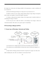
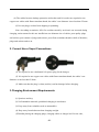
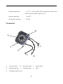
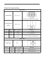
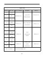
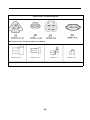
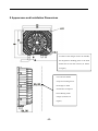
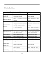
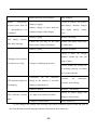
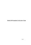
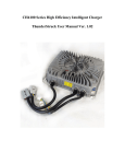
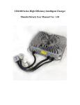
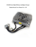
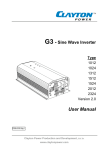
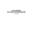
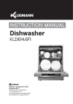
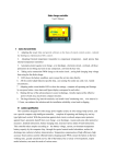
CH4100 Series High Efficiency Intelligent Charger
User Manual Ver.1.5.3
JWT GREATWAY ELECTRIC CO.,LTD
www.igreatway.com
Table Of Contents
I.Product Overview.......................................................................1
II.Safety Instructions.....................................................................2
III.Preventing Leakage and Fire................................................... 3
1.Correct use of Breakers, Sockets and Cables............................ 3
2.Correct Use of Input Connections............................................. 4
3.Charging Environment Requirements....................................... 4
IV.Regularly Maintenance............................................................ 5
IV.Product Models........................................................................ 5
V.Technical Specifications............................................................6
VI.parts list....................................................................................7
VII.Input and output interface...................................................... 8
VIII.Charging Indicator Information Description...................... 11
IX. Methods of Operation...........................................................12
X. Appearance and Installation Dimensions.............................. 13
XI.Faults & solutions..................................................................14
XII. Services............................................................................... 16
www.igreatway.com
Email:[email protected]
I Product Overview
CH4100 series high efficiency intelligent charger is designed to charge power batteries of
electric vehicles. This series of products adopt the most advanced technologies such as LLC
resonant, active power factor correction, microcomputer measurement and control, digital
adjusting, fully sealed waterproof technology and so on. Its features include: wide input voltage
range adapted to global general voltage; High input power factor that significantly reduces the
input current as well as heat generated by input cables, so the charger can be safely used in family;
Low harmonic current that reduces interference to other electric equipment. Full range soft
switching is realized to achieve high conversion efficiency and slight electromagnetic interference,
the charger is more energy-saving and money-saving to use; the charger is designed according to
IP66 protection grade and achieved high waterproof performance. Another feature includes small
size, light weight, quiet operation, beautiful appearance, simple installation, operation and
maintenance and so on.
The charger adopts microcomputer measurement and control technology, embedded CPU
can accurately detect various states of battery. Advanced multi-stage charging mode can prevent
the battery from be over-charged and over-discharged, minimize overheating and water loss
phenomenon caused by over-charge, slow down polar plate vulcanization phenomenon caused by
over-discharge, extend the service life of batteries. The charger will stop automatically after fully
charged.
The charger has functions of temperature compensation, automatically shut down after fully
charged, battery reverse connection protection, output short circuit protection, AC input
under-voltage protection, overheating protection and so on, and these functions can ensure safe
and reliable use.
-1-
II Safety Instructions
Please read these instructions carefully before you use the charger:
(1) For safety consideration, the charger adopts AC single-phase three-wire inputs which
contain live, neutral and protective grounding wire. The shell of charger connects protective
grounding wire. When using the charger, you should connect it to power grid with a quantified
16A three-hole socket which contains a grounding pole and controlled by a leakage protection air
breaker with leakage protection function to prevent leakage and fire.
(2) Please use dedicated 16A plug and socket of reliable quality for the charger (Socket
requirements: flame-retardant shell and cables of the socket, thick internal springs that not less
than 0.8mm and has a good elasticity), or it may burn the plug and socket, even cause severe fire!
Copper core cables thicker than GB 2.5mm2 are suggested to be used as power connections to
prevent the cables from becoming too hot when charging ,so to prevent fires.
(3) Please do not disassemble the charger; this may cause electric shock or other injuries.
(4) If the charger need to be connected to AC power supply with extension cables, please
make sure that the extension cable can withstand the maximum input current(GB 2.5mm2 copper
core cable is recommended to be used), and limit the extension cable length within 10m.
(5) Don’t place the charger in water or rain position; otherwise there is a danger that may
cause electric shock and damage to the charger.
(6) The charger’s DC output plug should be connected reliably to the socket, if they are
damaged or loose, please replace them immediately, otherwise it will cause overheating in the
plug position, and even cause serious fire.
(7) If the charger product any abnormal sound or smell during working, please unplug the
power plug immediately and contact the service department. Do not attempt to open the shell of
charger, to prevent electric shock.
(8) Make sure that all air vents are unobstructed to prevent charger overheating. Do not place
-2-
the charger near a heat source; the charger should be left enough space to ensure ventilation and
use of connectors.
(9) Please disconnecting the charger's AC input power if you need to move it.
(10) Make sure that AC power supply voltage matches chargers’ input voltage. For inquiries,
please contact your supplier or local power Supply Corporation.
(11) Battery voltage and the nominal voltage of the charger must be matched; otherwise it
will damage the charger or batteries.
(12) Do not pull, twist or shake the cables to avoid damage to the charger’s cables and
connection terminals. If the cable is worn, please replace it immediately.
III Preventing Leakage and Fire
1. Correct use of Breakers, Sockets and Cables
(1) Its required to use a leakage protection air breaker with leakage protection function.
(2) Its required to use reliable qualified 16A three-hole socket to connect the charger to AC
power.
(3) Input cables of leakage protection air breaker is required to use copper core cables with
flame-retardant jacket, the cables’ core diameter is not less than 2.5mm2.
-3-
(4) The cables between leakage protection air breaker and 16A socket are required to use
copper core cables with flame-retardant sheath, the cables’ core diameter is not less than 2.5mm2.
(5) Prevent plugs, sockets from dripping or splashing.
Note: According to statistics, 80% fire accident caused by an electric car occurred during
charging, main reasons for this are insufficient core diameter size of cables, poor quality plugs
and sockets, poor contact of plugs and sockets, poor flame-retardant sheath or shells of breakers,
plugs and sockets and so on.
2. Correct Use of Input Connections
(1) It’s required to use a dedicated 16A power plug for the charger;
(2) It’s required to use copper core cables with flame-retardant sheath; the cables’ core
diameter is not less than 2.5mm2.
(3) Make sure that the plug is clean (no dirty) and no damage before charging.
3.Charging Environment Requirements
(1) Spacious and airy;
(2) No flammable materials; prohibited charging in warehouse.
(3) Keep away from valuables such as automobiles.
(4) Keep away from bedroom when charging at night.
(5)Prohibit placing the charging plugs, charging cables or charger itself on car cabs,
-4-
plastics chairs and other inflammable objects.
IV Regularly Maintenance
(1) Check 16A sockets regularly, if the connection between the socket and the plug is loose
or poor contacting, they should be firmly connected or replaced before the charger be used. The
poor contact may result in overheating and burning of the plug and socket, and even cause a fire.
(2) Check the leakage protection air breaker regularly using the test button to ensure its
protection function is valid.
(3) Make sure to use a dedicated input cable and plug for the charger.
(4) Make sure that there are no foreign matters between the charger’s shell and the cooling
fan to avoid damage to the fan.
(5) Make sure that the appearance of battery is not ballooning; the battery is not
overheating when charging.
IV Product Models
1. Naming Rules
CH4100- XX XX X
Structure Code: Null for fixed application,
B for Portable application
Rated output current:15A, 20A, 25A,30A, 35A
Nominal output voltage:48V, 60V, 64V, 72V, 96V
Product Type :4th generation
-5-
2. Available Product Models
CH4100-4825, CH4100-4830,CH4100-4835
CH4100-6025, CH4100-6030,CH4100-6035
CH4100-6425, CH4100-6430,CH4100-6435
CH4100-7220, CH4100-7225,CH4100-7230
CH4100-9615, CH4100-9620,CH4100-9625
Note: Portable versions are available for above models, these models will be ended with
a structure code ‘B’ such as ‘CH4100-4825B’.
V Technical Specifications
Rated input voltage:
Input voltage range:
220Vac 50/60Hz
85~265Vac (Note: When the Input voltage is lower than
185Vac, the output power will be limited to 1.5KW)
Input Current:
≤ 16A (Note: except models of “CH4100-9625”)
Power Factor:
≥ 0.99 @ 220Vac input, full power output;
Total Harmonic Current:
≤ 5% @ 220Vac input, full power output;
Nominal output voltage (Un):
See Model Description
Maxim output voltage:
140%Un
Rated output current (Ir):
See Model Description
Voltage regulation accuracy:
≤ 0.5%
Current regulation accuracy:
≤ 2%
Conversion efficiency:
≥ 95% @ 220Vac input, full power output
Protection class:
IP66
Audible Noise:
≤ 40dB
Seismic rating:
Designed according to IEC60335-2-29-2004-Part.21
-6-
Working temperature:
-25~55℃ (Note: models whose output power greater than
2KW will ensure 2KW output at 60℃. )
Storage temperature:
- 40~80℃
Recognition certificates:
CE SGS
VI parts list
D
G
C
F
E
A
A
AC input Cables
B
D
Charging indicator
G
Cooling fan and fan cover
E
B
DC output cables
C
Signal Cables
Mounting plate
F
Shell
-7-
VII Input and output interface
Input Cables
Terminal Model
DJ7031-4.8-11
Direction of view: form the cables to terminal.
Terminal Model for
matching
DJ7031-4.8-21
Needle No.
Wire Color
Wire core diameter
Description
1#
brown
2.5 mm2
L——Live wire
2#
blue
2.5 mm2
N——Neutral wire
2.5 mm2
PE——Protective grounding wire
3#
Yellow
and green
Output Cables
Terminal Model
SB50
Needle No.
Wire Color
+
red
-
black
Wire core diameter
6
6 mm
Description
Output positive pole
mm2
Output negative pole
2
-8-
Signal Cables
Needle No.
Wire Color
1#
brown
2#
Blue
3#
yellow
4#
purple
Wire core diameter
DJ7031Y-2.3-21
DJ7021-1.5-21
5#
6#
7#
8#
9#
10#
11#
white
Description
Needle No.
external LED
DJ7031Y-2.3-11
indicator interface
Battery Temperature
sensor interface
DJ7021-1.5-11
pink
Yellow and
Serial
green
Blue and
DJ7043-2-21
communication
DJ7043-2-11
interface
white
Green and
white
orange
grey
Wire core diameter
Forbidden signal
DJ7021-2-11
interface
(normal close)
0.5 mm2 for all Signal wires
-9-
DJ7021-2-21
Signal Cables Terminal Diagram
Direction of view: form the cables to terminal.
DJ7031Y-2.3-11
DJ7021-1.5-11
DJ7043-2-11
-10-
DJ7021-2-21
VIII Charging Indicator Information Description
The charger installed a LED indicator internally, this built-in indicator display information
through the window on the shell of charger. Besides the charger provides an external LED
indicator interface that can connect the optional external LED indicator. Internal and external
LED indicator can light synchronously with "red, green, yellow" three colors; the LED indicator
can express a variety of working conditions of the charger with different color combinations. The
following table is a description of indicator information.
LED Indicator Information Description
I. Charging Process Information
1
Low battery power
R---
2
Battery charge lower than 80%
R-
3
Battery charge between 80%--90%
Y-
4
Battery charge between 90%--100%
G-
5
Full charge
Normal
process
of
continuous Green light
charging
Battery
temperature
Green light (3S) Yellow light (0.3s)
sensor fault
II. Alarm Information
1
Battery Not connected
R-G---
2
Charger over-temperature protection
R-G-Y---
3
Input fault protection
R-G-Y-Y---
4
Charging timeout
R-G-Y-Y-Y---
5
Battery Overheating
R-G-Y-Y-Y-Y---
-11-
6
Pre-Charge timeout
R-G-Y-Y-Y-Y-Y---
7
Internal temperature sensor fault
R-G-Y-Y-Y-Y-Y-Y---
8
Output voltage feedback fault
R-G-Y-Y-Y-Y-Y-Y -Y---
9
Low temperature start delay
R-G-Y-Y -Y-Y-Y-Y-Y-Y---
(When the internal temperature of
charger is between -20 to -30 ° C, the
charger will delay starting for 1~2
minutes)
Note:
1."-" represents led that does not light for 0.5s, a color word represents that the LED of this color
lights for 0.2s.
2. R --red
G —green Y—yellow
IX Methods of
(1) Connect the output terminal of the charger to the battery terminal
(2) Connect the input plug of the charger to AC power socket until the charger turns into
normal charging process (observe the LED Indicator), then Charger will automatically charge the
batteries. When fully charged, the charger will automatically shut down, and display ‘full power’.
(3) If observed the battery become overheating or ballooning during charging process, you
should stop the charger immediately by unplug the plug from the AC socket.
-12-
X Appearance and Installation Dimensions
If cables of the charger need to be bended,
the length from bending place to the shell
should not be less than 50 mm (as shown
in Figure).
Leave at least 50mm
away from cooling fan of
the charger to other
obstructions to improve
heat radiating of the
charger (as shown in
Figure).
-13-
XI Faults & solutions
If your charger can not work correctly, you can refer to table below
Fault Phenomenon
Analysis
Solutions
Battery temperature
External battery temperature sensor
Check sensor connection or
Sensor Fault
is fault or not connected
change a new one
Battery is not connected or reverse
Check and connect the battery
connected
correctly
Battery not connected
Place the charger in lower
Over-temperature
protection
Charging environment temperature
temperature environments and
is too high; cooling fan is fault;
recharge;
air vents are obstructed
Check whether cooling fan is
fault or air vents are obstructed
Poor contact of charger’s input
If no poor contact phenomenon
side ; Charger is broken
occurs, please contact us
Charging timeout
Battery is damaged or aging
Check and replace battery
Battery Overheating
Battery is damaged or aging
Check and replace battery
Pre-charge timeout
Battery is damaged or aging
Check and replace battery
Charger is broken inside
Please contact us
Charger is broken inside
Please contact us
Battery is broken;
Check whether the battery is
Poor contact between charger and
damaged; battery connecting
battery;
cables are firm ; the battery is
Input fault protection
Internal temperature
sensor fault
Output voltage
feedback fault
“Full Power ”after
short charging
-14-
Battery has been fully charged;
Battery
temperature
becomes more than 50
℃ and produces a lot
of bubbles
Low battery capacity
after fully charging
fully charged
Check the battery, and replace
Battery is aging ;
Battery voltage is lower than the
nominal voltage of the charger
bad battery; Reselect charger
that
match
battery
voltage
level .
Battery is aging
Replace the battery
Cables are too long or too thin
resume The output cables back
Between the charger and battery
to initial state
Battery is aging
Replace the battery
Check if there are foreign
matters around the fan and
Charging time becomes
too short or too long
Charger overheating protection
remove them
Check whether the cooling fan
is working correctly, or contact
us to replace the fan
Connectors
are
not
connected
LED indicator lights but
firmly, or the polarity is reversed;
no charging
Battery is disconnected
Battery is broken
LED indicator doesn’t
light
Connect
Charger is broken inside
connectors
correctly and recharge
Replace
AC input is not connected firmly
all
new battery
Check AC power supply and
chargers’ input cables
Please contact us
If your charger still cannot work correctly after above treatment, please record the state of
the fault phenomenon and charging indicator information, then contact us:
-15-
XII Services
If the charger has quality problems, you can change a new one within two months, and can
be repaired within one year free of charge. If the fault is caused by follow reasons, it cannot be
repaired free of charge:
(1) Damage caused by illegal operation.
(2) Without authorization, open the shell or repair, lead to damage.
(3) Damage caused by improper transportation, such as knocking, collision, or falling.
(4) Damage caused by water inlet, immersion, damp or other irresistible natural calamities.
(5) Damage caused by instantaneous over voltage in power grid (25% higher than Rated
input voltage).
(6) Damage caused by pulling input or output cable seriously.
For better services please follow attentions below:
(1) In warranty period, if faults occur in condition that all operations are according to user’s
manual, we will replace or repair free of charge.
(2) Warranty period and maintenance mode:From date of purchase within 12 month, free of
charge to repair. Users need to pay for reparation beyond warranty period.
(3) If faults happen within warranty period in follow cases, cost of material and service need
be paid appropriately:
A.Guarantee paper does not have the seal of distributor.
B.Fault caused by improper operation.
C.Fault caused by improper safekeeping and maintenance.
D.Damages cause by accident or disaster, such as natural disaster, war, or lightning strike.
E.Guarantee paper is damaged, or cannot be distinguished clearly.
(4) Out of warranty period, users need to pay for cost of material and service, spare parts can
have guarantee for 3 month from the date of reparation.
(5) If the guarantee paper does not record purchase date, warranty period will be 12 month
from date of delivery from factory.
-16-