1
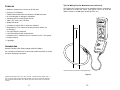
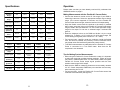
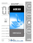
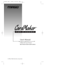
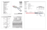
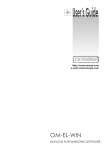
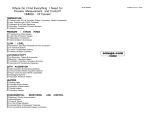
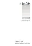
Where Do I Find Everything I Need for
Process Measurement and Control?
OMEGA ... Of Course!
M-3374/0899
99-MAN 100182
UserÕs
id
TEMPERATURE
3
o
o
3
o
3
o
3
3
o
Thermocouple, RTD & Thermistor Probes, Connectors, Panels & Assemblies
Wire: Thermocouple, RTD & Thermistor
Calibrators & Ice Point References
Recorders, Controllers & Process Monitors
Infrared Pyrometers
PRESSURE
/
STRAIN
3 Transducers & Strain Gauges
o
o
3 Load Cells & Pressure Gauges
o
3 Displacement Transducers
o
3 Instrumentation & Accessories
FLOW /
3
o
o
3
o
3
o
3
FORCE
LEVEL
Rotameters, Gas Mass Flowmeters & Flow Computers
Air Velocity Indicators
Turbine / Paddlewheel Systems
Totalizers & Batch Controllers
ON
OL
!
1000V CAT
III
10 mV/A
1 mV/A
OFF
pH/CONDUCTIVITY
®
3 pH Electrodes, Testers & Accessories
o
o
3 Benchtop / Laboratory Meters
3 Controllers, Calibrators, Simulators & Pumps
o
o
3 Industrial pH & Conductivity Equipment
http:/www.omeg
a.com
e-mail:
DATA ACQUISITION
3 Data Acquisition & Engineering Software
o
3 Communications-Based Acquisition Systems
o
o
3 Plug-in Cards for Apple, IBM & Compatibles
o
3 Datalogging Systems
o
3 Recorders, Printers & Plotters
HEATERS
3
o
o
3
o
3
o
3
o
3
Heating Cable
Cartridge & Strip Heaters
Immersion & Band Heaters
Flexible Heaters
Laboratory Heaters
ENVIRONMENTAL
3
o
o
3
o
3
o
3
o
3
3
o
MONITORING
AND
Metering & Control Instrumentation
Refractometers
Pumps & Tubing
Air, Soil & Water Monitors
Industrial Water & Wastewater Treatment
pH, Conductivity & Dissolved Oxygen Instruments
CONTROL
Flexible
AC Current Probes
HHM800 Series
WARRANTY/DISCLAIMER
OMEGA ENGINEERING, INC. warrants this unit to be free of defects in materials and workmanship for a
period of 13 months from date of purchase. OMEGA Warranty adds an additional one (1) month grace period
to the normal one (1) year product warranty to cover handling and shipping time. This ensures that
OMEGA's customers receive maximum coverage on each product.
If the unit should malfunction, it must be returned to the factory for evaluation. OMEGA's Customer Service
Department will issue an Authorized Return (AR) number immediately upon phone or written request. Upon
examination by OMEGA, if the unit is found to be defective it will be repaired or replaced at no charge.
OMEGA's WARRANTY does not apply to defects resulting from any action of the purchaser, including but not
limited to mishandling, improper interfacing, operation outside of design limits, improper repair, or
unauthorized modification. This WARRANTY is VOID if the unit shows evidence of having been tampered with
or shows evidence of being damaged as a result of excessive corrosion; or current, heat, moisture or
vibration; improper specification; misapplication; misuse or other operating conditions outside of OMEGA's
control. Components which wear are not warranted, including but not limited to contact points, fuses, and
triacs.
OMEGA is pleased to offer suggestions on the use of its various products. However, OMEGA neither
assumes responsibility for any omissions or errors nor assumes liability for any damages that result
from the use of its products in accordance with information provided by OMEGA, either verbal or
written. OMEGA warrants only that the parts manufactured by it will be as specified and free of
defects. OMEGA MAKES NO OTHER WARRANTIES OR REPRESENTATIONS OF ANY KIND
WHATSOEVER, EXPRESSED OR IMPLIED, EXCEPT THAT OF TITLE, AND ALL IMPLIED WARRANTIES
INCLUDING ANY WARRANTY OF MERCHANTABILITY AND FITNESS FOR A PARTICULAR PURPOSE
ARE HEREBY DISCLAIMED. LIMITATION OF LIABILITY: The remedies of purchaser set forth herein are
exclusive and the total liability of OMEGA with respect to this order, whether based on contract,
warranty, negligence, indemnification, strict liability or otherwise, shall not exceed the purchase price
of the component upon which liability is based. In no event shall OMEGA be liable for consequential,
incidental or special damages.
CONDITIONS: Equipment sold by OMEGA is not intended to be used, nor shall it be used: (1) as a "Basic
Component" under 10 CFR 21 (NRC), used in or with any nuclear installation or activity; or (2) in medical
applications or used on humans. Should any Product(s) be used in or with any nuclear installation or activity,
medical application, used on humans, or misused in any way, OMEGA assumes no responsibility as set forth
in our basic WARRANTY/DISCLAIMER language, and additionally, purchaser will indemnify OMEGA and hold
OMEGA harmless from any liability or damage whatsoever arising out of the use of the Product(s) in such a
manner.
OMEGAnetSM
On-Line
Service:
http://www.omega.com
Internet
e-mail:
[email protected]
Servicing North America:
USA:
ISO 9001 Certified
Canada:
976 Bergar
Laval (Quebec) H7L 5A1
Tel: (514) 856-6928
e-mail: [email protected]
1. P.O. number under which the product was
PURCHASED,
FOR NON-WARRANTY REPAIRS, consult
OMEGA for current repair charges. Have the
following information available BEFORE
contacting OMEGA:
2. Model and serial number of the product under
warranty, and
1. P.O. number to cover the COST of the repair,
3. Repair instructions and/or specific problems
relative to the product.
3. Repair instructions and/or specific problems
relative to the product.
2. Model and serial number of product, and
OMEGA's policy is to make running changes, not model changes, whenever an improvement is possible. This
affords our customers the latest in technology and engineering.
OMEGA is a registered trademark of OMEGA ENGINEERING, INC.
© Copyright 1996 OMEGA ENGINEERING, INC. All rights reserved. This document may not be copied,
photocopied, reproduced, translated, or reduced to any electronic medium or machine-readable form, in whole
or in part, without prior written consent of OMEGA ENGINEERING, INC.
FAX: (514) 856-6886
For Immediate Technical or Application Assistance:
Sales Service: 1-800-826-6342 1-800-TC-OMEGASM
Customer Service: 1-800-622-2378 / 1-800-622-BESTSM
Engineering Service: 1-800-872-9436 / 1-800-USA-WHENSM
TELEX: 996404 EASYLINK 62968934 CABLE: OMEGA
Mexico and
Latin America:
Tel: (95) 800-TC-OMEGASM
FAX: (95) 203-359-7807
En Espanol: (203) 359-1660 ext: 2203
e-mail: [email protected]
Benelux:
Postbus 8034,1180 LA Amstelveen, The Netherlands
Tel: (31) 20 6418405
FAX: (31) 20 6434643
Toll Free in Benelux: 06 0993344 e-mail: [email protected]
Czech Republic:
Ostravska 767, 733 01 Karvina
Tel: 420 (69) 6311627
e-mail: [email protected]
France:
9, rue Denis Papin, 78190 Trappes
Tel: (33) 130-621-400
FAX: (33) 130-699-120
Toll Free/France: 0800-4-06342
e-mail: [email protected]
Germany/Austria:
Daimlerstrasse 26, D-75392 Deckenpfronn, Germany
Tel: 49 (07056) 3017
FAX: 49 (07056) 8540
Toll Free in Germany: 0130 11 21 66
e-mail: [email protected]
United Kingdom:
25 Swannington Road,
Broughton Astley, Leicestershire,
LE9 6TU, England
Tel: 44 (1455) 285520
FAX: 44 (1455) 283912
Servicing Europe:
The purchaser is responsible for shipping charges, freight, insurance and proper packaging to prevent
breakage in transit.
FOR WARRANTY RETURNS, please have the following
information available BEFORE contacting OMEGA:
FAX: (203) 359-7700
USA and Canada:
RETURN REQUESTS/ INQUIRIES
Direct all warranty and repair requests/inquiries to the OMEGA Customer Service Department. BEFORE
RETURNING ANY PRODUCT(S) TO OMEGA, PURCHASER MUST OBTAIN AN AUTHORIZED RETURN
(AR) NUMBER FROM OMEGA'S CUSTOMER SERVICE DEPARTMENT (IN ORDER TO AVOID
PROCESSING DELAYS). The assigned AR number should then be marked on the outside of the return
package and on any correspondence.
One Omega Drive, Box 4047
Stamford, CT 06907-0047
Tel: (203) 359-1660
e-mail: [email protected]
150 9002 Certified
FAX: 420 (69) 6311114
P.O. Box 7, Omega Drive,
Irlam, Manchester,
M44 5EX, England
Tel: 44 (161) 777-6611
FAX: 44 (161) 777-6622
Toll Free in England: 0800-488-488
e-mail: [email protected]
It is the policy of OMEGA to comply with all worldwide safety and EMC/EMI regulations that apply.
OMEGA is constantly pursuing certification of its products to the European New Approach
Directives. OMEGA will add the CE mark to every appropriate device upon certification.
The information contained in this document is believed to be correct but OMEGA Engineering, Inc
accepts no liability for any errors it contains, and reserves the right to alter specifications without
notice.
WARNING: These products are not designed for use in, and should not be used for, patient
connected applications.
Notes:
Table of Contents
Warning ................................................................................................... 2
International Electrical Symbols............................................................. 3
Receiving Your Shipment....................................................................... 3
Packaging ............................................................................................... 3
Description .............................................................................................. 4
Features .................................................................................................. 6
Accessories............................................................................................. 6
Standard Models..................................................................................... 7
Specifications.......................................................................................... 8
Instrument Compatibility....................................................................... 12
Operation .............................................................................................. 13
Making Measurements w/ the Flexible AC Current Probes ......... 13
Tips for Making Precise Measurements ....................................... 13
Typical Response Curves.............................................................. 17
Maintenance ......................................................................................... 19
Warning .......................................................................................... 19
Battery Replacement ..................................................................... 19
Cleaning ......................................................................................... 19
Warning
Maintenance
These safety warnings are provided to ensure the safety of
personnel and proper operation of the instrument.
Warning
· Read the instruction manual completely and follow all the safety
information before attempting to use or service this instrument.
· Wear protective clothing and gloves as required.
· Use caution on any circuit: potentially high voltages and currents
may be present and may pose a shock hazard.
· Read the Safety Specifications section prior to using the current
probe. Never exceed the maximum voltage ratings given.
· Safety is the responsibility of the operator. The Flexible AC
Current Probe must be used only by qualified personnel using
applicable safety precautions.
· ALWAYS de-energize the circuit before wrapping the Flexible
AC Current Probe around bare conductors, bus bars, or near live
parts. Do not wrap on live conductors.
· ALWAYS connect the electronic module to the display device
before wrapping the Flexible AC Current Probe around the
sample being tested.
· ALWAYS inspect the module, sensor, sensor cable, and output
terminals prior to use. Replace any defective parts immediately.
Use only factory parts.
· NEVER use the Flexible AC Current Probe on electrical
conductors rated above 1000 V in overvoltage category III.
· For maintenance use only specified replacement parts.
· Avoid electrical shock: do not attempt to perform any servicing
unless you are qualified to do so.
· Do not perform any service while the Flexible AC Current Probe is
on any circuit.
· Avoid electrical shock and/or damage to the instrument: do not get
water or other foreign agents into the electronic module.
· Also see warning on page 2.
Battery Replacement
· If the power ON indicator (green LED) blinks or does not light up,
replace the battery.
· Remove the Flexible AC Current Probe from any circuit before
replacing the battery.
· To replace the battery, open rear case, replace battery and
reassemble. The green LED should go on when the module is
turned on.
Cleaning
· It is important to keep the probe sensor latch mating surfaces
clean and prevent foreign bodies from hampering the closing. The
sensor may be gently cleaned with a soft cloth, soap and water.
Dry immediately after cleaning. Avoid water penetration into the
electronic module.
· Make sure the sensor, electronic module, and all leads are dry
before any further use.
2
19
Typical Response Curves (cont.):
International
Symbols
This symbol signifies that the probes are protected by double or
reinforced insulation. Use only specified replacement parts when
servicing the instrument.
Typical Phase Shift vs. Frequency @ 200 A, 1 mV/A Output
5°
0°
This symbol signifies CAUTION! and requests that the user refer
to the user manual before using the instrument.
-5°
Degrees
Electrical
-10°
-15°
Receiving
-20°
-25°
1 Hz
10 Hz
100 Hz
1000 Hz
10 kHz
100 kHz
Frequency
Current Derating Curve (I < 3000 A)
Your
Shipment
Upon receiving your shipment, make sure that the contents are
consistent with the packing list. Notify Omega of any missing items. If the
equipment appears to be damaged, file a claim immediately with the
carrier and notify Omega at once, giving a detailed description of any
damage.
Amps
3000 A
2500 A
Packaging
2000 A
Your Flexible AC Current Probe consists of the following items:
1500 A
· Flexible probe with electronic module
· Users manual
· 9V battery
1000 A
500 A
0A
1000 Hz
10 kHz
100 kHz
Frequency
Current Derating Curve (I > 3000 A)
30 kA
25 kA
Amps
20 kA
15 kA
10 kA
5 kA
0A
100 Hz
1000 Hz
10 kHz
100 kHz
Frequency
18
3
Typical Response Curves:
Description
The Flexible AC Current Probe is a flexible AC current transformer
composed of a flexible sensor and an electronic module. The flexible
sensor permits measurements on conductors where standard clamp-on
probes could not be used. In particular, it can be installed in tight spaces,
around breaker panels, around cable bundles, around wide or large bus
bars, or even wrapped around irregular shapes. The Shape Memoryª
feature enables the user to Òpre-shapeÓ the sensor before inserting it
between or around conductors. This feature facilitates closing, enhances
user safety, and alleviates the drooping effect typically associated with
flexible sensors.
The Flexible AC Current Probe is lightweight. It does not use magnetic
cores like standard transformers. The transformation principle is based
on an air core. It presents virtually no load to the system under test, has
a low phase shift and excellent frequency response, and cannot be
damaged by overloads. The sensor assembly is waterproof and
insulated for 1000 V Cat. III. The Flexible AC Current Probe meets IEC
1010, is CE marked (1997).
The Flexible AC Current Probe has a mV output proportional to the
current measured for direct readings on DMMs, data loggers,
oscilloscopes, and power or harmonic meters. TRMS measurements are
taken when connected to a TRMS meter. The Flexible AC Current Probe
is insensitive to DC currents and only the AC component of the
measured signal is measured.
The length of the flexible sensor can be selected in lengths of 24", 36",
and 48" in length. Consult the factory for custom lengths, ranges and/or
features.
Typical Accuracy vs. Frequency @ 100 A, 1 mV/A Output
0.00 %
-0.50 %
-1.00 %
-1.50 %
-2.00 %
-2.50 %
-3.00 %
1 Hz
10 Hz
100 Hz
1000 Hz
10 kHz
100 kHz
Frequency
Typical Accuracy % vs. Frequency @ 100 A, 10 mV/A
0.00 %
- 1.00 %
- 2.00 %
- 3.00 %
- 4.00 %
- 5.00 %
- 6.00 %
- 7.00 %
1 Hz
10 Hz
100 Hz
1000 Hz
10 kHz
100 kHz
Frequency
Typical Accuracy % per Range to 100 A
%
± 10
±9
±8
±7
20 A ... 3000 A
10 kA ... 30 kA
±6
±5
±4
±3
±2
±1
±0
0.1 A
4
0.5 A
1A
5A
17
10 A
50 A
100 A
Tips for Making Precise Measurements (continued):
HHM800 SERIES
2
1
5 0 0 .0
MV
3
ACV•
250 A
4
DCV
6
ON
5
COM
+
OL
!
1000V CAT
III
10 mV/A
1 mV/A
OFF
®
9
ON
!
OL
1000V CAT
III
10 mV/A
1 mV/A
OFF
®
8
7
Figure 1
1. Positive: Red Banana Plug (+)
Double the turns to double the output in low
current applications or for higher sensitivity
Figure 4
7. Flexible Sensor
(Diameter 0.5", 12.5 mm)
2. Common: Black Banana Plug (-)
3. Power ON Indicator (green LED)
4. Overload Indicator (red LED)
9. Electronic Module Descriptive Label on Back
Case (range, model, etc.)
5. Range Selection Switch
6. Connector/Latch
16
8. Lead from Sensor to Module
(6.5 ft, 2m)
5
Tips for Making Precise Measurements (continued):
Features
·
·
·
·
·
·
·
·
·
Models to measure from 0.5 Arms to 30,000 Arms
Accuracy 1% of Reading
TRMS measurements when connected to a TRMS instrument
No core saturation or damage if overloaded
Overrange LED for measurement circuitry
1000 V, IEC 1010 Cat III, CE Mark
Waterproof sensor
9 V battery for typical 150 hr continuous operation
Shape Memoryª for custom pre-shaping of sensor before use
(no drooping)
·
·
·
·
·
Very high frequency response
Low phase shift for power measurements
Insensitive to DC, measures only AC component on DC + AC signals
Excellent linearity
Lightweight
The Flexible AC Current Probe may be doubled around the conductor to
be measured to double the output. (See figures 3 and 4 to show the
different values on a DMM while measuring 250 A AC.)
2 5 0 .0
250 A
ACV•
DCV
COM
+
ON
!
OL
1000V CAT
III
10 mV/A
1 mV/A
OFF
Accessories
Banana (Female) / BNC (Male) Adapter (HHM70-CONN1)
®
For connection of Flexible AC Current Probe to BNC terminals on scopes
and other displaying instruments.
One turn around a conductor carrying 250 A AC
Figure 3
*Reference Conditions: 25¡C ± 5¡K, 20 to 75% RH, 1 minute warm-up, battery at 9V ±
0.5V, conductor center, external DC magnetic field < 40 A/m, no external AC magnetic
field, no external electrical field, 10 to 100 Hz, sine wave. See accuracy curves for low
currents.
6
15
MV
Tips for Making Precise Measurements (continued):
· To increase the sensitivity or measure on low currents, the Flexible AC
Current Probe may be wrapped several times around the conductor.
Remember to divide your reading by the number of turns for the
actual measurement (see figure 4).
· The overall measurement accuracy is the sum of the Flexible AC
Current Probe accuracy and the displaying instrument accuracy.
ON
!
OL
1000V CAT
III
10 mV/A
1 mV/A
OFF
®
For best accuracy, center the
Flexible AC Current Probe
Standard
Models
Model
Number
Current
Range
Length
Diameter
# of
Output
Ranges
mV
Outputs
HMM801
30 A
24 in / 610 mm
7.64 in / 190 mm
1
100 mV/A
HMM802
200 A
24 in / 610 mm
7.64 in / 190 mm
1
1 mV/A
HMM803
300 A
24 in / 610 mm
7.64 in / 190 mm
1
10 mV/A
HMM804
300 A
24 in / 610 mm
7.64 in / 190 mm
1
1 mV/A
HMM805
30/300 A
24 in / 610 mm
7.64 in / 190 mm
2
100 or 10 mV/A
HMM806
500 A
24 in / 610 mm
7.64 in / 190 mm
1
1 mV/A
HMM807
50/500 A
24 in / 610 mm
7.64 in / 190 mm
2
10 or 1 mV/A
HMM808
1000 A
24 in / 610 mm
7.64 in / 190 mm
1
1 mV/A
HMM809
100/1000 A
24 in / 610 mm
7.64 in / 190 mm
2
10 or 1 mV/A
HMM810
3000 A
24 in / 610 mm
7.64 in / 190 mm
1
1 mV/A
HMM811
300/3000 A
24 in / 610 mm
7.64 in / 190 mm
2
10 or 1 mV/A
HMM812
6000 A
24 in / 610 mm
7.64 in / 190 mm
1
0.1 mV/A
HMM813
600/6000 A
24 in / 610 mm
7.64 in / 190 mm
2
1 or 0.1 mV/A
HMM814
10,000 A
24 in / 610 mm
7.64 in / 190 mm
1
0.1 mV/A
HMM815
1000/10,000 A
24 in / 610 mm
7.64 in / 190 mm
2
1 or 0.1 mV/A
HMM816
30,000 A
24 in / 610 mm
7.64 in / 190 mm
1
0.1 mV/A
HMM817
3000/30,000 A
24 in / 610 mm
7.64 in / 190 mm
2
1 or 0.1 mV/A
HHM70-CONN1 - Accessory Adaptor (See Accessories, page 6)
Figure 2
*Standard length is 610 mm (24Ó). Please consult sales for availability and pricing for 910,
1220 and 1520 mm (36, 48 and 60Ó) models. Comes with 9V battery and operatorÕs
manual.
14
7
Specifications
Operation
Model #
HHM801
HHM802
HHM803
HHM804
HHM805
Please make sure that you have already read and fully understand the
WARNING section on page 2.
Operating
Range
30 A
200 A
300 A
300 A
30/300 A
Making Measurements with the Flexible AC Current Probe:
Measurement
Range
5-30 A
5-200 A
5-300 A
5-300 A
5-300 A
Output Signal
100 mV/A
1 mV/A
10 mV/A
1 mV/A
100 mV/A or
10 mV/A
Crest Factor
(mid-range)
3.0
> 10
3.0
> 10
3.0
Phase Shift
@ 50/60 Hz
1.3¡
0.7¡
0.7¡
0.7¡
1.3¡
Residual
Noise
200 mA
200 mA
200 mA
200 mA
200 mA
DC Offset
50 mV
2 mV
5 mV
2 mV
50 mV or
5 mV
Model #
HHM806
HHM807
HHM808
HHM809
Operating
Range
500 A
50/500 A
1000 A
100/1000 A
Measurement
Range
5-500 A
5-500 A
5-1000 A
5-1000 A
Output Signal
1 mV/A
10 mV/A or
1 mV/A
1 mV/A
10 mV/A or
1 mV/A
Crest Factor
(mid-range)
> 10
> 10
9.0
9.0
Phase Shift
@ 50/60 Hz
0.7¡
0.7¡
0.7¡
0.7¡
Residual Noise
200 mA
200 mA
200 mA
200 mA
DC Offset
2 mV
5 mV or 2 mV
2 mV
5 mV or 2 mV
8
· Connect the electronic module to the AC Volt range of your DMM or
measuring instrument. Select the appropriate module output voltage
range. If the current magnitude is unknown, and if the Flexible AC
Current Probe has two ranges, select the lowest mV/A output setting.
· Wrap the flexible core around the conductor to be tested. If possible
within range, select the higher mV/A Flexible AC Current Probe output
range to obtain the best resolution. Do not exceed specified current
range for the output. Do not use on selected range if overload LED
goes on.
· Read the displayed value on the DMM and divide it by the range
selected (i.e. if reading = 2.59 V with the 10 mV/A output range, the
current flowing through the probe is 2590 mV Ö 10 = 259A).
· For best accuracy, carefully center the conductor inside the flexible
core, and avoid if possible, the proximity of other conductors which
may create noise and interference (particularly near the latch).
· True RMS measurements are obtained when the Flexible AC Current
Probe is connected to a True RMS meter. Note that the DC
component is not measured.
Tips for Making Precise Measurements:
· When using the Flexible AC Current Probe with a meter, it is important
to select the range that provides the best resolution. Failure to do this
may result in measurement errors. For best results, select the highest
Flexible AC Current Probe output signal possible and the most
sensitive meter range for this output.
· Make sure the DMM or measuring instrument can accurately measure
mV AC. Certain inexpensive DMM have poor resolution and accuracy
when measuring low mV AC.
· For best accuracy, center the Flexible AC Current Probe around the
conductor to be measured. (See figure 2).
13
MATERIAL SPECIFICATIONS
Specifications
Module:
UL 94V2, Color dark gray, Polycarbonate
Sensor Latch:
Material: Lexan 500R, UL94V0
Cable Assembly to Sensor:
UL 94V0, 1000 V rating
SAFETY SPECIFICATIONS
Electrical:
Double insulation or reinforced insulation between primary, secondary
and outer case of handle per IEC 1010-1 @ 2 (indoor use)
· 1000 V Category III, Pollution Degree 2
· 600 V Common Mode
· 7.50 kV, 50/60 Hz, dielectric between secondary and the outer case
Instrument
Compatibility
The Flexible AC Current Probe is compatible with any multimeter, AC
voltmeter, or other voltage measuring instrument with an input
impedance greater than 1MW. To achieve the best overall accuracy, use
the Flexible AC Current Probe with a AC voltmeter having an accuracy of
0.75% or better.
12
Model #
HHM810
HHM811
HHM812
HHM813
Operating
Range
3000 A
300/3000 A
6000 A
600/6000 A
Measurement
Range
5-3000 A
5-3000 A
5-6000 A
5-6000 A
Output Signal
1 mV/A
10 mV/A or
1 mV/A
0.1 mV/A
1 mV/A or
0.1 mV/A
Crest Factor
(mid-range)
3.0
3.0
> 10
> 10
Phase Shift
@ 50/60 Hz
0.7¡
0.7¡
0.5¡
0.5¡
Residual Noise
200 mA
200 mA
500 mA
500 mA
DC Offset
2 mV
5 mV or 2 mV
1 mV
2 mV or 1 mV
Model #
HHM814
HHM815
HHM816
HHM817
Operating
Range
10,000 A
1000/10,000 A
30,000 A
3000/30,000 A
Measurement
Range
5-10,000 A
5-10,000 A
5-30,000 A
5-30,000 A
Output Signal
0.1 mV/A
1 mV/A or
0.1 mV/A
0.1 mV/A
1 mV/A or
0.1 mV/A
Crest Factor
(mid-range)
9.0
9.0
3.0
3.0
Phase Shift
@ 50/60 Hz
0.5¡
0.5¡
0.5¡
0.5¡
Residual Noise
500 mA
500 mA
500 mA
500 mA
DC Offset
1 mV
2 mV or 1 mV
1 mV
2 mV or 1 mV
*Reference Conditions: 25¡C ± 5¡K, 20 to 75% RH, 1 minute warm-up, battery at 9V ± 0.5V, conductor
center, external DC magnetic field < 40 A/m, no external AC magnetic field, no external electrical field,
10 to 100 Hz, sine wave. See accuracy curves for low currents.
9
Common Specifications
MECHANICAL SPECIFICATIONS
Module Output:
Two 4 mm safety banana jacks
Standard 3/4" (19 mm) spacing
ELECTRICAL
Accuracy: 1% of reading
Frequency Range:
10 - 20,000 Hz with current derating
Battery: 9V Alkaline (NEDA 1604A, IEC 6LR61) recommended
Signal Output: 4.5 V max.
Battery Life: Useable from 9V to 7V, 150 hours typical (continuous use)
Working Voltage: 1000 V, IEC 1010 Cat. III
Low Battery: Power ON indicator (green LED) when battery voltage
³ 7 V, LED blinks when battery voltage is low
Common Mode Voltage: 600 V
Frequency Influence:
See Accuracy vs. Frequency curves on pages 17 and 18.
Overload Indication: Red LED ON indicates the selected range is
overloaded. Module output may not reflect the actual measurement
Frequency Limitation:
See current derating curves (note no limitation on 300 A Range) pg. 18.
Dimensions (sensor): 24" nominal (+/- 1"), other lengths optional
Influence of adjacent conductor in contact
with sensor and with AC signal:
0.2% typical, 2% maximum
Connection Cable Length (sensor to module): 6.5 ft (2 m)
Influence of conductor position in sensor: 0.5% typical, 4% maximum
Influence of shape of sensor:
Oblong shape: 0.2% typical, 1% maximum
Common Mode Rejection: 100 dB typical, 80 dB minimum
ENVIRONMENTAL SPECIFICATIONS
Case Protection:
Sensor: IP65 per IEC 529
Electronic module: IP40 per IEC 529
Operating Temperature Range: 10¡C to +55¡C (14¡F to 131¡F)
Dimensions (Electronic Module): 4.9 x 2.5 x 1.1" (124 x 64 x 28 mm)
Colors: Red sensor with dark gray connector and module, black
connection cable (sensor to module)
Drop Test: Per IEC 68-2-32
Vibration: Per IEC 68-2-6
Mechanical Shock: Per IEC 68-2-27
Weatherproofing:
Module: IP40 (EN 60529)
Sensor: IP 65 (EN60529) - NEMA 4X
SENSOR SPECIFICATIONS:
Storage Temperature Range: -40¡C to +70¡C (-40¡F to 158¡F)
Weight: 30g/10cm
Influence of Temperature:
Sensor: -10¡C to 90¡C: 0.15% per 10¡C typical, 0.5% per 10¡C max.
Module: -10¡C to 55¡C: 0.15% per 10¡C typical, 0.5% per 10¡C max.
Bend Radius: 0.75" (19mm) minimum
Influence of Relative Humidity:
10 to 90% RH: 0.2% typical, 0.5% maximum
Bending Life: >10,000 without performance deterioration
Waterproofing: Permanent to spray, IP 65
Resistance to Chemicals: Resistant to oils and aliphatic hydrocarbons
Operating Relative Humidity:
10 - 30¡C 85 ± 5% RH (without condensation)
40 - 50¡C 45 ± 5% RH (without condensation)
Diameter: 12 mm +/- 0.5 mm
Altitude:
Operating: 0 to 2000 m, working voltage derating above
Non-operating: 0 to 12,000 m
Dielectric Strength: 7500 V
10
Outer Sheath Material: Polyurethane, UL94V0
Latch Spring Life: >10,000 maneuvers
11