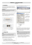
1
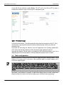
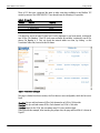
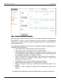
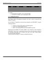
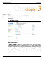
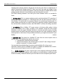
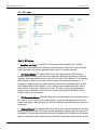
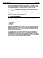
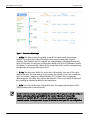
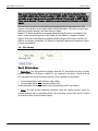
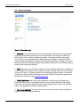
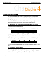
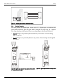
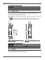
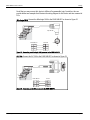
Modbus TCP to DF1 Converter
EGW1-MB-DF1
User´s Manual
Internet Enabling Solutions
www.exemys.com
EGW1-MB-DF1 User Manual
Introduction
Exemys Products are in constant evolution to satisfy our customers’ needs.
For that reason, the specifications and capabilities are subject to change without prior notice.
Updated information can be found at www.exemys.com
Copyright © Exemys, 2005 All Rights Reserved.
Rev. 1.1.0
www.exemys.com
Rev. 1.1.0
Page 2
EGW1-MB-DF1 User Manual
Introduction
Table of Contents
INTRODUCTION
5
GETTING STARTED
6
2.1
Wiring instructions ____________________________________________________ 6
2.2
Network Configuration_________________________________________________ 7
2.3
Serial port configuration________________________________________________ 8
2.4
Tables configuration___________________________________________________ 9
2.5
Polling the device____________________________________________________ 12
ADVANCED TOPICS
14
3.1
Modbus TCP page ___________________________________________________ 14
3.2
DF1 page __________________________________________________________ 16
3.3
Translation Tables page _______________________________________________ 17
3.4
Site Survey_________________________________________________________ 19
3.5
Statistics page ______________________________________________________ 20
3.6
Advanced page _____________________________________________________ 21
3.7
Transparent Mode page _______________________________________________ 22
THE EMBEDDED MODBUS TCP SLAVE
www.exemys.com
23
4.1
Enabling the slave ___________________________________________________ 23
4.2
Monitoring and controlling built-in digital inputs and outputs ___________________ 23
4.3
Looking at internal statistics____________________________________________ 23
A. TEXT-BASED CONSOLES
25
B. CABLING
27
B.1.
Power ____________________________________________________________ 27
B.2.
Ground ___________________________________________________________ 27
B.3.
Ethernet Connection _________________________________________________ 27
B.4.
Digital Inputs _______________________________________________________ 28
B.5.
Digital Outputs _____________________________________________________ 29
Rev. 1.1.0
Page 3
EGW1-MB-DF1 User Manual
B.6.
Introduction
RS232 Port_________________________________________________________ 29
C. PING-BASED METHOD FOR IP CONFIGURATION
31
D. MONITORING THE DEVICE THROUGH THE BUILT-IN LEDS
32
E. CONFIGURING FLEXLOGIX AND CONTROLLOGIX PLCS
33
Tables
Table 1 - Available Models ___________________________________________________________________5
Table 2 - IO Capacity ______________________________________________________________________10
Table 3 - Text-based consoles operation ________________________________________________________25
Table 4 - Commands set ____________________________________________________________________26
Table 5 - Digital Inputs - Technical Specifications__________________________________________________29
Table 6 - Digital Outputs - Technical Specifications ________________________________________________29
Table 7 - ARP entries for typical Operating Systems ________________________________________________31
Table 8 - Yellow LED_______________________________________________________________________32
Table 9 - Green LED _______________________________________________________________________32
Figures
Figure 1 – Wiring intructions__________________________________________________________________6
Figure 2 – Exemys Device Locator listing detected devices in the LAN ___________________________________7
Figure 3 - Configuring network parameters _______________________________________________________8
Figure 4 - EGW1-MB-DF1 home page ___________________________________________________________8
Figure 5 - DF1 configuration page ______________________________________________________________9
Figure 6 - Translation Tables page_____________________________________________________________10
Figure 7 - Translation Tables filled with PLC information ____________________________________________11
Figure 8 - Handling incoming Modbus TCP Requests _______________________________________________13
Figure 9 - Modbus TCP web page _____________________________________________________________14
Figure 10 - DF1 web page___________________________________________________________________16
Figure 11 - Translation Table web page_________________________________________________________18
Figure 12 - Site Survey web page _____________________________________________________________19
Figure 13 - Statistics web page _______________________________________________________________20
Figure 14 - Advanced web page ______________________________________________________________21
Figure 15 - Transparent Mode web page ________________________________________________________22
Figure 16 - Power Input Connection Scheme _____________________________________________________27
Figure 17 - Connecting the device to an Ethernet Network___________________________________________28
Figure 18 - Digital Input connected to an external device with an independent power supply _________________28
Figure 19 - Digital input connected to a dry contact________________________________________________28
Figure 20 - The load and the Exemys device using two different power supplies ___________________________29
Figure 21 - The load and the Exemys device share its power supply ____________________________________29
Figure 22 - Connecting one Micrologix 1000 processor to the EGW1-MB-DF1_____________________________30
Figure 23 - Connecting an SLC 500 processor to the EGW1-MB-DF1____________________________________30
www.exemys.com
Rev. 1.1.0
Page 4
EGW1-MB-DF1 User Manual
Introduction
Chapter 1
Chapter
Introduction
Thank you for your purchase! EGW1-MB-DF1 is a Modbus TCP to DF1 gateway. EGW1-MB-DF1
lets you gain access to a wide range of industrial devices that talk DF1 protocol just by using
Modbus TCP, a de facto standard in the industrial field.
As a bonus, EGW1-MB-DF1 incorporates the following features:
An embedded Modbus TCP slave, which provides built-in digital I/O for remote sensing and
controlling (four inputs and four outputs) and statistics reports.
Easily upload and download programs to the remote PLC using your usual application. Just
work as if you had a serial cable installed between the PLC and your computer, but relying on the
benefits of Ethernet.
Configuration and monitoring of the device can be performed by an embedded web server, a
telnet-like console or a serial console.
Table 1 - Available Models
www.exemys.com
Model
Serial
Protocol
Ethernet
Protocol
Inputs
Outputs
Serial Ports
EGW1 - 1044 - MB - DF1
DF1
Modbus TCP
4
4
RS-232
Rev. 1.1.0
Page 5
EGW1-MB-DF1 User’s Manual
Getting Started
Chapter 2
Chapter
Getting Started
This chapter shows how to get your new EGW1-MB-DF1 started. It focuses on the main features
of this product, that is, Modbus TCP to DF1 conversion. This chapter briefly explains how to
connect the cables, power up and configure the device in order to start issuing commands to a
PLC.
2.1 Wiring instructions
Power supply and RS-232 port: These signals are located in the top green connectors.
Detach the green connectors before screwing the cables to ease the wiring.
TIP
Ethernet: Plug a CAT 5 cable between the RJ45 connector and a port in your hub or switch.
Figure 1 shows the basic wiring. Refer to Appendix B if you need more details.
Power Supply
9-30 VDC
9-26 VAC
Vin
Vin
GND
RxD To PLC´s RS232
TxD Port
10 Base-T
CAT 5
A
B
Figure 1 – Wiring intructions
www.exemys.com
Rev. 1.1.0
Page 6
EGW1-MB-DF1 User’s Manual
Getting Started
2.2 Network Configuration
Power the device on and run Exemys Device Locator (EDL), the application software for instant
location and network configuration. It must be executed in the same broadcast domain as EGW1MB-DF1. EDL can be found in the CD provided.
You may download EDL from http://www.exemys.com
ON THE WEB
When EDL detects the device, it lists its data into a table, as shown in Figure 2.
Figure 2 – Exemys Device Locator listing detected devices in the LAN
Select the device and click on Properties. The Device Properties window will appear.
You may obtain EGW1-MB-DF1’s IP address dynamically (via a DHCP server in your network) or
statically.
In this case, we will choose the static method. Assuming the network address is 192.168.0.0/16,
we take an IP address, lets say 192.168.0.53. Then, network parameters will be configured as
shown in Figure 3.
Always pick an unused IP address in the network.
NOTE
www.exemys.com
Rev. 1.1.0
Page 7
EGW1-MB-DF1 User’s Manual
Getting Started
Figure 3 - Configuring network parameters
2.3 Serial port configuration
Open a web browser and type the IP address of the device in the Address field. Following this
example, it would be http://192.168.0.53. Figure 4 shows the home page.
Figure 4 - EGW1-MB-DF1 home page
www.exemys.com
Rev. 1.1.0
Page 8
EGW1-MB-DF1 User’s Manual
Getting Started
On the left side you will find a menu (Modbus TCP, DF1 and so on). Click on DF1 in order to
configure the serial port. Figure 5 shows the DF1 configuration page.
Figure 5 - DF1 configuration page
Click on the Detect button. This will automatically detect baud rate and parity of the PLC. If this
detection fails, a pop-up will notify that no device could be detected. In that case, check the
wiring and retry.
Once baud rate and parity are detected, select the appropriate Error Checking method (BCC,
CRC). Please note that this parameter must be the equal to that configured in the PLC.
Regarding the Requests Timeout option, try keeping the 1000 milliseconds default, since it is an
adequate value for most environments. You may modify this parameter later, if needed.
2.4 Tables configuration
Protocol conversion is based on tables that store the mapping between incoming requests (using
Modbus TCP protocol) and PLC data areas. Table translation applies for internal memory, but is
not used for Inputs/Outputs.
NOTE
As a factory default , many newer PLCs (such as FlexLogix and ControlLogix) do not provide
compatibility with the type of request issued by the EGW1-MB-DF1. However, they do provide a
mechanism to make them downwards-compatible with other PLCs and with the EGW1-MB-DF1.
Please refer to Appendix E if you are attempting to connect one of the PLCs above to the EGW1MB-DF1.
Henceforth, a real situation is proposed. It might differ slightly from your actual configuration,
though we think of an study case as the best way to get in touch with your new gateway.
www.exemys.com
Rev. 1.1.0
Page 9
EGW1-MB-DF1 User’s Manual
Getting Started
There is PLC that runs a program. We want to make some data available to one Modbus TCP
master by means of the EGW1-MB-DF1. These boards have the following I/O capacities:
Table 2 - IO Capacity
Module
Feature
Capacity
1
2
3
4
16 Digital Inputs
32 Digital Outputs
4 Analog Outputs
32 Digital Inputs
1 word
2 words
4 words
2 words
It is desired to access not only I/O data, but it is also important to read some words, contained in
two N Files (File Numbers 7 and 10) and some read/write bit variables, contained in one B File,
whose File Number is 3. First, we check the internal tables are clean, by clicking on the
Translation Tables link, located on the left frame.
Figure 6 - Translation Tables page
The page is divided into three sections, the first three are user-configurable, while the last one is
fixed.
N section lets you add and remove N Files. Each element in an N File is 16-bits wide.
B section lets you add and remove B Files. Each element in a B File is 1 bit wide.
S section stands for the S File, the area where many PLCs store statistics data.
Going on with the example, after inserting the proper data, the page will look like it is shown in
Figure 7.
www.exemys.com
Rev. 1.1.0
Page 10
EGW1-MB-DF1 User’s Manual
Getting Started
Figure 7 - Translation Tables filled with PLC information
Input and outputs modules connected to the PLC do not require any further configuration in the
EGW1-MB-DF1. In order to access the modules, the end user will have to issue appropriate
Modbus requests, thus the protocol converter will translate them into DF1 commands which can
be understood by the PLC.
The mapping between Modbus and DF1 protocol for Input/Output modules is straightforward. It is
summarized in the following rules:
Input modules can be read through Inputs Status or Input Register.
Output modules can be read through Coil Status or Holding Register.
Each Holding Register or Input Register is associated to one word (16 bits). Thus, each
word contained in a module is assigned to one Modbus location, either Holding Register
or Input Register (generically, one “Register” location).
Each Coil Status or Input Status is associated to one bit. Thus, each bit contained in a
module is assigned to one Modbus location, either Coil Status o a Input Status
(generically, one “Status” location).
The multiple coils write command only allows a write to a single coil.
Modules with less than one word use one complete Modbus “Register”.
Requests to “Register” locations up to address 64 are assumed to be requests for the
modules.
Requests to “Status” locations up to address 1024 are assumed to be requests for the
modules.
The modules will be addressed as shown in the following table, according to the rules above.
www.exemys.com
Rev. 1.1.0
Page 11
EGW1-MB-DF1 User’s Manual
Module
1
2
3
4
Getting Started
Coil Status
Input Status
Holding Register
10001-10016
Input Register
30001-30001
00001-00032
40001-40002
10017-10080
30002-30005
00033-00064
40003-40004
For example:
To read output 20 in module 2, ask for Coil Status 00021.
To read word 3 in module 3, ask for Input Register 30004
2.5 Polling the device
After filling the tables with appropriate information, the device is ready to accept polls from
Modbus TCP masters.
Run your Modbus TCP application as usual and issue commands to the EGW1-MB-DF1, using the
following parameters:
IP address: 192.168.0.53 (the same you assigned using EDL)
TCP port: 502 (standard Modbus TCP port)
Unit ID: 1 (it is a factory default, but it can be modified at any time)
Recall that the only Modbus TCP locations available to your master(s) are those assigned by
EGW1-MB-DF1. That is why it is important that the user counts on the information contained in
the Translation Tables page, such as Modbus Point Types (Coils Status, Holding Register,
etceteras) and address boundaries.
Figure 8 illustrates how Modbus TCP requests are handled by the device.
www.exemys.com
Rev. 1.1.0
Page 12
EGW1-MB-DF1 User’s Manual
Getting Started
MB/TCP Request
Modbus TCP Master
Table Look Up
MB/TCP DF1
Protocol Translation
DF1 Request
PLC
DF1 Reply
A
MB/TCP Reply
DF1 B MB/TCP
Protocol Translation
Figure 8 - Handling incoming Modbus TCP Requests
www.exemys.com
Rev. 1.1.0
Page 13
EGW1-MB-DF1 User’s Manual
Advanced Topics
Chapter 3
Chapter
Advanced Topics
Chapter 2 outlined some basic features of the EGW1-MB-DF1 protocol converted. However, for
the sake of clarity, many other aspects where not covered there. Those topics are covered in detail
in this chapter.
3.1 Modbus TCP page
1
2
3
4
5
Figure 9 - Modbus TCP web page
1. Network parameters: EGW1-MB-DF1 default IP address is 0.0.0.0. Thus, unless you set a
static IP address, it will attempt to get an IP address from a DHCP server. The device tries to
negotiate an IP address with a DHCP server for a maximum period of 10 seconds. If a DHCP server
fails to answer in that period, EGW1-MB-DF1 will show an error code through the frontal LEDs
(refer to Appendix D for a list of error codes) and then it will retry other DHCP negotiations every
60 seconds. This process will be repeated until the negotiation succeeds.
You may also assign a static IP address, through a ping-based method (see Appendix C for details
on this method).
www.exemys.com
Rev. 1.1.0
Page 14
EGW1-MB-DF1 User’s Manual
Advanced Topics
Changing these network parameters through the web has the same effect as configuring the IP
address, Netmask and Gateway using EDL. Please note that if you make any change to these
values, the web service (actually every network connection) will only be available with the newer
settings and after the device is reset (software reset takes about three seconds).
The Default Gateway parameter is not used by the current firmware version. It is intended for
future
releases.
2. TCP Keep Alives: This is a common mechanism used to early detect broken TCP connections. If
enabled (by setting this parameter to a value bigger than zero) the device will send a frame to
those Modbus TCP masters that do not generate requests for a period longer than this value. If a
master answers the keep alive, no action is taken on its connection. However, should this query
fail, the link will be considered as broken, thus EGW1-MB-DF1 will abort the failing connection.
3. TCP Buffering: When a Modbus TCP request arrives to the device while another is being
served, two decisions can be taken, according to this parameter: discard the latest request
(Disabled) or buffer the request (Enabled). Note that in case that you buffer requests, the delay
between requests and replies may result longer than expected, since other command(s) could be
already queued. In other words, in heavy loaded environments, you might notice timeouts in your
Modbus
TCP
masters.
4. Embedded Slave: The device has a Modbus TCP slave that can receive requests from an
external master. The embedded slave provides two services:
Control/monitor of built-in inputs and outputs,
Report internal statistics. (See Statistics page in section 3.5 and Looking at internal
statistics in section 4.1 for further details).
You may disable the embedded slave if you do not need the built-in I/O or if you are not
interested in statistics reports via Modbus TCP requests. If enabled, the embedded slave receives
and processes external requests issued to the Unit ID configured.
5.
Modbus Exceptions: The term exception refers to the mechanism defined by the Modbus
specification to signal error conditions, such as polling to an invalid address or polling too many
locations in memory. Disable this feature if you do not want to receive exceptions upon a failure.
www.exemys.com
Rev. 1.1.0
Page 15
EGW1-MB-DF1 User’s Manual
Advanced Topics
3.2 DF1 page
1
2
3
4
5
Figure 10 - DF1 web page
1. Baud Rate and Parity: It is possible to set these parameters manually, that is, without
detecting these link parameters by clicking on the Detect button. These fields could be filled by
hand if you want to set the serial parameters before the PLC is actually connected.
2. DF1 Source Address: DF1 frames define Source (SRC) and Destination (DST) addresses,
corresponding to the stations that want to exchange data. While these parameters seem to be
important, most implementations do not take care of its values. This is because DF1 is commonly
used as a point to point protocol, where only two stations are connected to the wire. As a
consequence, addresses are not a matter. However, there are two associated protocols, called
Data Highway (DH) and Data Highway + (DH+), which provide communication paths among
many stations. In these cases, addresses are a must. This field, as well as the one described
below, provide compatibility for those protocols, when interfacing the EGW1-MB-DF1 with a
DH/DH+ network, using an adapter.
3. DF1 Destination Address: This field defines the Destination Address to be used when issuing
DF1 requests. You can choose to use a fixed address, or copy the same address received at the
Modbus side. Again, if running legacy DF1, this field and the one described above do not need to
be changed.
4. Requests Timeout: This timeout defines the round trip time, measured between the incoming
request is removed from the TCP/IP buffer and the appropriate answer is ready to be sent back to
the Modbus TCP master. When the buffering feature is enabled (see TCP buffering in the previous
page), the queue time is not considered a part of this time. This timeout will only run when a new
www.exemys.com
Rev. 1.1.0
Page 16
EGW1-MB-DF1 User’s Manual
Advanced Topics
frame is processed. In other words, when the load is heavy enough to queue frames, you might
notice timeouts in the Modbus TCP master(s), but not exceptions due to time exceeded. Those
timeouts are the ones configured at each master and not the one provided in this field.
5. Error Checking: Two methods are provided by the DF1 specification to detect frame errors,
BCC and CRC. BCC is a one-octet field appended to a DF1 frame. It contains a checksum of many
bytes contained in the message. By the other hand, the CRC, which stands for Cyclic Redundancy
Check and is two-octets long, is a more robust method in the sense that it will detect more errors
than BCC. This setting must be coherent with that configured in the PLC: if the PLC is set to BCC
you have to set EGW1-MB-DF1 to use BCC and vice versa.
3.3 Translation Tables page
In this sections, some basic aspects on Modbus TCP and DF1 protocols are outlined.
Modbus TCP data are classified into four types, such as defined in Modbus ASCII/RTU.
These areas are known as:
Input Registers
Holding Registers
Input Status
Coil Status
Input Registers and Holding Registers are 16-bit words, while Input Status and Coils Status are
mapped to discrete 1-bit data. By the other hand Input Registers and Input Status are read-only
areas, used to read input data such as digital inputs and statistics. Holding Registers and Coils
Status areas may be both read and written.
PLCs compatible with DF1 protocol usually map addressable data into Files and Elements. A
group of data with similar characteristics is called a File and each datum within a File is an
Element. Files are organized into File Types, according to their different purposes. For example, N
Files are used to store 16-bit integers, B Files store bit variables and the O File is used to write a
value to a PLC output. Each File is associated to a unique File Number.
www.exemys.com
Rev. 1.1.0
Page 17
EGW1-MB-DF1 User’s Manual
Advanced Topics
1
2
3
4
Figure 11 - Translation Table web page
1. N Files: This table provides the capability to map N Files, which usually store program
variables. Up to thirty two N Files will be allowed, thus covering a wide range of typical
situations. Each Element in the File is mapped into Holding Registers, allowing both reads and
writes (16 bits wide). The only entry to know before adding an N File is its File Number. (Usually
File Number 7 is associated with a default N File, though other N Files could be configured using
the application software provided with your PLC).
2. B Files: This table stores the Bit File, used to keep 1 bit variables. Up to two B Files can be
added to the table. This might seem an scarce resource, but actually it is not. Have in mind that
each 1-bit location is mapped to a different Modbus TCP Coil Status, thus consuming the
addressing space very quickly. Also consider that these two B Files lets you map 8192 individual
bits, providing an adequate capability for most applications.
3. S File: This is the only fixed (non-configurable) table. The mapping (Input Registers 3019230447) provides reads of internal statistics.
NOTE
www.exemys.com
In order to work accurately, I/O expansion boards and other Files in general have to be configured
with the application software provided by the PLC vendor. Otherwise, the Files will be
unavailable to the EGW1-MB-DF1, which will return Modbus exceptions (if enabled) upon
unsolved requests. Contact you dealer for specific information about your PLC and configuration.
Rev. 1.1.0
Page 18
EGW1-MB-DF1 User’s Manual
Advanced Topics
Many newer PLCs (such as FlexLogix and ControlLogix) do not provide (as a factory default)
compatibility with the type of request issued by the EGW1-MB-DF1. However, they do provide a
mechanism to make them downwards-compatible with other PLCs and with the EGW1-MB-DF1.
Please refer to Appendix E if you are attempting to connect one of the PLCs above to the EGW1MB-DF1.
You can insert a record into an intermediate position by selecting the appropriate row. After
insertion, rows below the insertion point will be shifted downwards. If you insert erroneous data,
delete the record by selecting it and then clicking on Delete.
Modbus TCP address boundaries are assigned automatically by the device. For example, if you
insert a record into the first position of the N Table, the first Element is mapped to Holding
Register 40192, the second Element is mapped to Holding Register 40193 and so on. Thus, you
will have to configure your Modbus TCP master(s) to make polls within those boundaries in order
to obtain valid answers.
3.4 Site Survey
1
2
Figure 12 - Site Survey web page
1. Device Type: This field provides information about the PLC detected by the device. Actually,
protocol conversion is not based on which PLC you connected to the device. Instead, only two
DF1 commands were chosen for all data transfers. Those commands are specified as
Protected typed logical read with three address fields
Protected typed logical write with three address fields
Further information on these commands can be obtained from the DF1 specification.
2. Status: This field provides important information about the current processor status (for
example running mode or programming mode). This information is useful, since the PLC must be
in run mode in order to accept remote requests.
www.exemys.com
Rev. 1.1.0
Page 19
EGW1-MB-DF1 User’s Manual
Advanced Topics
3.5 Statistics page
Figure 13 - Statistics web page
EGW1-MB-DF1 keeps an internal statistics, related to successful and failed transactions. Think of
this feature as a powerful tool when debugging your system. This service is available not only
through this web page, but it also could be monitored through the embedded Modbus TCP slave
(if enabled, see Chapter 4) or through a telnet-like console (see Appendix A).
www.exemys.com
Rev. 1.1.0
Page 20
EGW1-MB-DF1 User’s Manual
Advanced Topics
3.6 Advanced page
1
2
3
4
Figure 14 - Advanced web page
1. Password: To avoid undesired access to the configuration, the web service can be passwordprotected. (The telnet-like console will use the same password, if this feature is enabled. The
serial console, since it is local to the protocol converter, is inherently safer than any network
access, thus it is not password-protected). Maximum password length is 10 characters. When
password checking is enabled, an authentication page will pop up prior to allowing any access to
the web. Disable this checking by setting a new password as blank (click on the Change Password
button without setting any password).
2. Reset: This button resets the device. Program is restarted, pending requests are discarded and
volatile variables (for example, statistics data) are restored to start-up values, just as if the device
was power off and on. This button should not be needed during regular operation. It is provided
to restore the system remotely. Should you need to reset the device for any reason, please do not
feel hesitate to contact our team: [email protected]
3. Disable Web Server: Web service can be disabled for security reasons by clicking on this
button. Note that as soon as you disable the web service you will not be able to load any web
page. There are two ways to enable this service again: using the serial console or the telnet-like
console. (See Appendix A for details on both consoles).
4. Set to Factory Defaults: You may set the device to factory values (e.g. recover configuration,
clean the tables) by clicking on this button.
www.exemys.com
Rev. 1.1.0
Page 21
EGW1-MB-DF1 User’s Manual
Advanced Topics
3.7 Transparent Mode page
Figure 15 - Transparent Mode web page
The transparent mode provides the remote programming capability. Using this mode, you can use
EGW1-MB-DF1 to upload and download programs to the PLC, just like if you connected the PLC
to your PC through a serial port. This is done by encapsulating serial data into a TCP/IP
connection. No Modbus TCP transactions are allowed in this mode. Moreover, if any Modbus TCP
was established before you switch to Transparent Mode, they will be closed. Think of this mode
as a tool for program updating, but using a TCP/IP connection on the Ethernet port. To accomplish
this, you will have to count on a port redirector application, running at the computer side. This
software, available from many vendors, redirects traffic from a virtual COM port to a TCP/IP
connection. Then, your PLC software will talk to the redirector software, which in turn will
encapsulate the data into TCP/IP packets. EGW1-MB-DF1 in turn will receive TCP/IP data and will
perform the inverse task. In other words, the key idea of the port redirector applications is data
encapsulation (in a two-way manner). If you need further assistance on port redirectors, please
contact Exemys.
The port redirector application inside your PC must be configured to establish a raw connection to
the EGW1-MB-DF1’s IP address, TPC port as it is configured in the device (see Figure 15). You will
also have to select a virtual COM port number to receive outgoing and accept incoming traffic.
Once this application is running, open the application software for the PLC, having in mind that
the serial COM must be configured to match the virtual port created by the port redirector.
When you finish configuring your PLC, close the PLC software and then switch back to Gateway
Mode in order to return to normal mode.
www.exemys.com
Rev. 1.1.0
Page 22
EGW1-MB-DF1 User’s Manual
The Embedded Modbus TCP Slave
Chapter 4
Chapter
The Embedded Modbus TCP Slave
This chapter explains how to take advantage of the embedded Modbus TCP slave. Remote
inputs/outputs and device statistics are made visible to the user though this service.
4.1 Enabling the slave
Refer to Embedded Slave in section 3.1 to enable the statistics service by web. If you prefer to
monitor statistics using a text-based console, see Text-Based Consoles, Appendix A.
4.2 Monitoring and controlling built-in digital inputs and outputs
Input and output pins are located in the bottom connectors of the EGW1-MB-DF1 case. Refer to
Cabling, Appendix B for location of these pins.
The four digital inputs are mapped to Input Status locations, as shown in the following table:
Pin Number
Digital Input
Input Status
9
I0
10001
10
I1
10002
11
I2
10003
12
I3
10004
Recall that Input Status locations are read-only variables. After you issue a read input command,
the pins are read and the measure is reported through the answer.
The four digital outputs are mapped to Coil Status locations, as shown in the following table:
Pin Number
Digital Input
Coil Status
13
O0
00001
14
O1
00002
15
O2
00003
16
O3
00004
Coil Status locations are read-write variables. Thus, both reads and writes are allowed for the I/O
pins.
4.3
Looking at internal statistics
You can monitor the internal statistics by reading Modbus locations. These data are the same that
those provided through the web service. Think of this method as a way to gather statistics by
means of a SCADA that eventually could store a log just by issuing periodical Modbus TCP reads.
Statistics registers are made public through Input Status locations, as shown below
www.exemys.com
Rev. 1.1.0
Page 23
EGW1-MB-DF1 User’s Manual
The Embedded Modbus TCP Slave
Meaning
Input Status
Malformed requests
Discarded requests due to buffer overflow
Table look-up misses
Requests discarded
Embedded Slave
Requests accepted
Successful transactions
Gateway
Timed out
Requests discarded due to serial errors
Errors reported by the PLC
Valid requests
30001-30002
30003-30004
30005-30006
30007-30008
30009-30010
30011-30012
30013-30014
30015-30016
30017-30018
30019-30020
Registers shown above in bold letters represent the totals (i.e. a request is either malformed,
discarded because the TCP buffering feature is disabled or valid). By the other hand, the addition
of the remaining registers compound the valid requests. We call valid requests to those that can
be processed, disregarding whether they contain solvable or unsolvable requests. For example if
no translation could be performed because the target was not found in the tables, the request is
syntactically valid, though it cannot be solved (this is known as a table look-up miss).
Note that two Input Status are used to represent each record. This is because the internal
representation of the counters is 32 bits wide. The first Input Status shows the upper 16 bits and
the second Input Status shows the remaining (least significant bits).
To reset the statistics using the Modbus TCP Slave, just write any value to Holding Register
40001.
www.exemys.com
Rev. 1.1.0
Page 24
EGW1-MB-DF1 User Manual
Introduction
Appendix A
Appendix
A.Text-Based Consoles
This Exemys device provide two text-based consoles, one serial console and one telnet-like (TCP)
console. Both provide full control of your device, just like the web service does.
The serial console can be chosen if you feel concerned about security (in order to operate this
console you need to a dedicated cable and be close to the device) .
The telnet-like console provides a raw TCP channel to configure the device issuing clear text
commands. This console can be used throughout the network (actually, it could be available to
the global Internet), so it can be protected by a password. Console password is the same as that
used to access the embedded HTTP server.
Table 3 provides the directions to open both consoles
Table 3 - Text-based consoles operation
To open this console…
You have to…
1) Disconnect the serial cable to the PLC.
2) Connect the device to a computer COM port as follows:
Serial console
EGW1-MB-DF1 (pin #)
Computer DB9 COM port (pin #)
RX (5)
TXD (3)
TX (6)
RXD (2)
GND (4)
GND (5)
4) Open a terminal (9600 bits per second, 8N1).
3) Power off and on the device.
4) Type CFG and press Enter within the first 7 seconds.
Telnet-like console
Open a terminal (at any time)
IP address: EGW1-MB-DF1’s IP address
TCP port: 23
Both consoles provide an on-line help, with the full command set. Type HELP in your terminal to
receive a detailed description of available commands.
Table 4 lists the commands set and associated references inside this user’s manual.
www.exemys.com
Rev. 2.0.0
Page 25
EGW1-MB-DF1 User Manual
Introduction
Table 4 - Commands set
Command
TCP/IP commands
IP
NETMASK
GATEWAY
KA
TCPBUFFER
TRANSPORT
Modbus-related commands
MBEXCEP
MSGTOUT
SLVCFG
DF1-related commands
BAUD
PARITY
AUTOCOM
ERROR
SRCADDR
DSTADDR
DSTCFG
Table-related commands
TBLRST
TBLVIEW
TBLDEL
TBLINS
General commands
STATSLIST
STATSCLEAR
MODE
RESET
FACTRESET
LIST
PASSWORD
WEBCFG
HELP
END
www.exemys.com
Description
Refer to section
EGW1-MB-DF1's IP address
EGW1-MB-DF1's network mask
Gateway to be used by EGW1-MB-DF1
TCP connections Keep alives
TCP/IP buffering for Modbus TCP commands
TCP/IP incoming port for transparent mode
3.1
3.7
Generate Modbus TCP Exceptions
Messages timeout
Embedded Modbus Slave
3.1
Baud rate
Parity
Automatically detect baud rate and parity for DF1 link
Error detection mechanism
DF1 source address
DF1 destination address
DF1 destination address option
3.2
Reset all tables to factory defaults
View the contents of a Translation Table
Delete one row from a Translation Table
Insert one row into a Translation Table
3.3
List communication statistics
Clear communication statistics
Select working mode
Restarts the device
Restores factory defaults
List Network and General Configuration
Remote Configuration Password
Web server
Display the help screen
Finish configuration
Rev. 2.0.0
4.3
3.7
3.6
3.6
-
Page 26
EGW1-MB-DF1 User´s Manual
Cabling
Appendix B
Appendix
B.Cabling
B.1.
Power
Figure 16 shows the power input connection, which is located in the Vin terminals.
EGW1-MB-DF1 powering has no polarity and accepts an input voltage range of 9 to 30 VDC and
9 to 26 VAC.
9-30 VDC
9-26 VAC
Vin
Vin
Figure 16 - Power Input Connection Scheme
B.2.
Ground
The GND pin (pin number 4) is the digital ground signal used to the provide grounding reference
to the digital I/Os and the RS-232 port.
B.3.
Ethernet Connection
The device can be connected to a LAN through a Hub or Switch (using a straight through cable).
Both cases are illustrated in Figure 17.
www.exemys.com
Rev. 2.0.0
Page 27
EGW1-MB-DF1 User´s Manual
Cabling
A
B
RX+ (1)
(1) RX+
RX- (2)
(2) RX-
TX+ (3)
(3) TX+
TX- (6)
(6) TX-
Exemys
Device
HUB
Figure 17 - Connecting the device to an Ethernet Network
B.4.
Digital Inputs
This device provides four digital inputs located at pins 9-12. Digital inputs are terminated with
current-sinking transistors. Inputs are active when a voltage in the range 3.5-28 Vdc is applied.
This voltage may be provided by two different ways, depending on the external field device:
Case A) Voltage is self-provided by the external device, that works as a current-sourcing
node. (See Figure 18)
Case B) Voltage is not provided by the device (dry contact). External voltage must be applied.
(See Figure 19)
9-30 VDC
9-26 VAC
Power Supply
9-30 VDC
9-26 VAC
Power Supply
+
+
Vin
Vin
Vin
2
1
GND
3
Vin
1
6
GND
3
4
4
5
5
2
6
7
8
8
7
Power
Field Device
(PLC, Sensor, Encoder, etc)
Power
A
+Vdc
A
COMMON
B
OUTPUT Voltage
(3.5 a 28 VDC Max.)
(Sourcing)
B
Power Supply
of the Device
10BaseT
10BaseT
EGW1
EGW1
9
9
10
11
I0
13
13
14
15
11
12
14
15
16
16
Figure 18 - Digital Input connected to an external device with
an independent power supply
www.exemys.com
10
IØ
12
Rev. 2.0.0
Figure 19 - Digital input connected to a dry contact
Page 28
EGW1-MB-DF1 User´s Manual
Cabling
Table 5 - Digital Inputs - Technical Specifications
Digital Inputs
Sinking. Allow dry contacts and current sourcing devices
Inputs Type
Operating Voltage Range
Input Current
B.5.
3.5 - 28 Vdc
1 - 11 mA
Digital Outputs
This device provides four digital outputs located at pins 13-16. Digital outputs are Open Collector.
This means that when active, outputs are electrically tied to GND. Any load connected to an
output should be powered in the range 3 - 45 Vdc .
When connecting an output to an external load, two situations may occur. These situations are
covered below.
Case A) The external load and the Exemys device use different power supplies. (Figure 20)
Case B) The external load and the Exemys device share the same power supply. (Figure 21)
9-30 VDC
9-26 VAC
Power Supply
9-30 VDC
9-26 VAC
Power Supply
+
+
Vin
Vin
1
5
2
6
7
Vin
GND
3
Vin
1
4
5
8
6
B
10BaseT
A
B
LOAD
Relay / Lamp,
etc.
10BaseT
EGW1
9
11
15
10
11
12
12
13
14
8
LOAD
Relay / Lamp,
etc.
3-45 VDC
Power
Supply
EGW1
13
7
4
+
A
10
GND
3
Power
Power
9
2
16
14
15
16
OØ
OØ
Figure 20 - The load and the Exemys device using two
different power supplies
Figure 21 - The load and the Exemys device share its
power supply
Table 6 - Digital Outputs - Technical Specifications
Digital Outputs
Output Type
Maximum Load Voltage
Current
B.6.
Open Collector. Current Sinking
3 - 45 Vdc Max.
130mA Max. Per output
RS232 Port
This product provides an RS232 port, which is used to connect the device to the PLC. It is also
used to configure the device through the serial console.
www.exemys.com
Rev. 2.0.0
Page 29
EGW1-MB-DF1 User´s Manual
Cabling
Recall that you may connect this device to different Programmable Logic Controllers, thus we
provide below two examples that illustrate the wiring diagram for this device and two commercial
PLCs.
Micrologix 1000: Connect the Micrologix 1000 to the EGW1-MB-DF1 as shown in Figure 22
8-pin Mini Din
4
5
7
6
EGW1-MB-DF1
MLX 1000
4
GND
GND
2
6
Tx
RxD
4
5
Rx
TxD
7
4
2
Figure 22 - Connecting one Micrologix 1000 processor to the EGW1-MB-DF1
SLC 500: Connect the SLC 500 to the EGW1-MB-DF1 as shown in Figure 23
5
3
2
4
5
6
EGW1-MB-DF1
SLC500
4
GND
GND
5
6
Tx
RxD
2
5
Rx
TxD
3
Figure 23 - Connecting an SLC 500 processor to the EGW1-MB-DF1
www.exemys.com
Rev. 2.0.0
Page 30
EGW1-MB-DF1 User’s Manual
Ping-based method for IP configuration
Appendix C
Appendix
C.Ping-based method for IP configuration
When the device receives an ICMP request (usually known as a ping command) within the first 7
seconds after it is powered on, it configures its IP address based on the destination IP address of
that packet.
Before sending the ping, a static entry must be added to the ARP table of the computer used to
send the command. This entry will insert a mapping between a target IP address an its
corresponding MAC (physical) address. The MAC address is printed on the case.
Assume the following scenario:
Desired IP address
MAC address
192.168.0.53
00-0b-fa-30-03-7b
The command ARP depends slightly on the Operating Systems, as shown in Table 7:
Table 7 - ARP entries for typical Operating Systems
If you are running this OS
Insert an ARP entry by typing…
Windows (all)
arp –s 192.168.0.53 00-0b-fa-30-03-7b
Unix (all)
arp –s 192.168.0.53 00:0b:fa:30:03:7b
(You may check if the entry was inserted by executing arp –a)
Then type ping 192.168.0.53 –t within the first 7 seconds. The –t option causes the ping to
be sent continuously. Power off and on the device. Once the device starts to reply to the ping
command, it will be ready to be operated over the network.
www.exemys.com
Rev. 2.0.0
Page 31
EGW1-MB-DF1 User’s Manual
Monitoring the device through the built-in LEDs
Appendix D
Appendix
D.Monitoring the device through the built-in LEDs
The LEDs located close to the RJ-45 connector provide status information about the device, rather
than flashing upon Ethernet collisions. The meaning of the blinking is provided in the following
tables.
Table 8 - Yellow LED
If the yellow LED is…
that means…
½ a second on and ½ a second off
Device has been turned on and it is initializing.
Turned on constantly
Looking for a DHCP server
Blinking fast
No carrier detected on the Ethernet port
Turned off for about one second and then goes
on for a short lapse (like a beacon)
Turned on for about one second and the goes
off for a short lapse
IP address assigned and device working properly
Ethernet carrier detected but no IP Address assigned.
Table 9 - Green LED
www.exemys.com
If the green LED is…
that means…
Steady on
At least, one TCP connection is established (except HTTP connection)
Blinking
One valid frame received (either on the Ethernet port or on the RS-232 port)
Rev. 2.0.0
Page 32
SSE232-ST User’s Manual
Exemys
Appendix E
Appendix
E.Configuring FlexLogix and ControlLogix PLCs
Time ago, Allen Bradley came out with some modifications about the way that newer PLCs
exchange data. In the new approach, the PLC defines tags to map data, rather than Files. At the
moment of this publication, those PLCs belong to the FlexLogix and ControlLogix family. The new
commands are not compatible with EGW1-MB-DF1, yet. However, AB provides downwardscompatibility with the old command set. Recall that EGW1-MB-DF1 only uses the Protected typed
logical read with three address fields and Protected typed logical write with three address fields
DF1 commands and it does not count on specific PLC information, such as processor, model or
firmware version.
Here we provide some basic information to activate the downward compatibility feature with
RSLogix 5000.
To map an address:
1. In RSLogix 5000 software, open the project file for the controller whose
data you want to access
2. From the Logic menu, select Map PLC/SLC Messages
3. The screen shown will be used to provide the actual mapping between an
already defined tag and the File Number you choose to make public to
EGW1-MB-DF1. Complete the information required as an SLC mapping.
(Choose an appropriate File Number). The tags must be controller-scoped
(global).
4. Click OK
If you want to map many data into one File, you can define a tag as an array.
NOTE
www.exemys.com
Rev. 2.0.0
Page 33