1
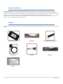
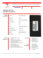
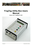
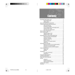
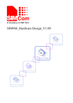
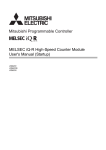
NAXERTECH LIMITED NTT-101 GPS Vehicle Tracking system Operational Manual NaxerTech Limited Regus House, Herald Way, Pegasus Business Park, Castle Donington DE74 2TZ United Kingdom Tel: +44 (0)1509 808168 E- Mail: [email protected] Thank you for purchasing the NaxerTech’s GPS/ GPRS Fleet Management and Tracking device. Please read all instructions carefully before operation, to ensure your complete understanding and to obtain the best possible performance from the Tracking Unit. The NaxerTech Limited warrants to the purchaser that this product, under normal use and conditions, will be free from defects in materials and workmanship for a period of 12 months from the date of original purchase. If a product proves defective during this warranty period, NAXERTECH LIMITED, at its option, either will repair the defective product without charge for parts and labor, or will provide an exchange for the defective pr oduct. In order to obtain service under this warranty, the purchaser must notify NAXERTECH LIMITED of the defect before the expiration of the warranty period and make suitable arrangements for the performance of service. The purchaser shall be responsible for appropriate packaging a nd shipping with a carrier designated by NAXERTECH LIMITED, with shipping charges paid by recipient (NAXERTECH LIMITED). This warranty shall not apply to any defect, failure or damage caused by improper use or improper or inadequate maintenance a nd care, alterations, mishandling or accidents. NAXERTECH LIMITED shall not be obligated to furnish service under this warranty to costs incurred for installation, to correction of antenna problems, removal or reinstallation or to damage to video tapes, discs, speakers, accessories or vehicle electrica l system. The extend of NAXERTECH LIMITED’s liability under this warranty is limited to the repair or replacement provided above and, in no event, shall the company’s liability exceed the purchase price paid for this product. THIS WARRANTY IS GIVEN BY NAXERTECH LIMITED IN LIEU OF ANY OTHER WARRANTIES, EXPRESS OR IMPLIED. NAXERTECH LIMITED AND ITS VENDORS DISCLAIM ANY IMPLIED WARRANTIES OF MERCHANTABILITY OR FITNESS FOR A PARTICULAR PURPOSE. NAXERTECH LIMITED’S RESPONSIBILITY TO REPAIR OR REPLACE DEFECTIVE PRODUCTS IS THE SOLE AND EXCLUSIVE REMEDY PROVIDED TO THE PURCHASER FOR BREACH OF THIS WARRANTY. NAXERTECH LIMITED AND ITS VENDORS WILL NOT BE LIABLE FOR ANY INDIRECT, SPECIAL, INCIDENTAL OR CONSEQUENTIAL DAMAGES IRRESPECTIVE OF WHETHER NAXERTECH LIMITED OR THE VENDOR HAS ADVANCE NOTICE OF THE POSSIBILITY OF SUCH DAMAGES. CE Compliance Statement. This equipment has been tested and found to comply with the limits for EN55022 and EN55024 standards . This equipment generates uses and can radiate radio frequency energy and, i f not installed and used in accordance with the instructions, may cause harmful interference to radio communications. This device complies with CE Rules. Operation is subject to the following two conditions: (1). This device may not cause harm ful interference, and (2) this device must accept any interference received, including interference that may cause undesired operation. CE Caution: Any changes or modifications not expressly approved by the party responsible for compliance could void the user's authority to operate this equipment. This transmitter must not be co-located or operating in conjunction with any other antenna or transmitter. INFORMATION TO USER: The user’s manual or instruction manual for an intentional or unintentional radiator shall c aution the user that changes or modifications not expressly approved by the party responsible for compliance could void the user’s authority to operate the equipment. 2|P a ge Table of Contents General Introduction ....................................................................................................................................................... 5 Package ........................................................................................................................................................................... 5 Device Features ............................................................................................................................................................... 6 General Specifications .................................................................................................................................................. 6 Functional Specifications .............................................................................................................................................. 6 Main Components........................................................................................................................................................ 6 About Document: ......................................................................................................................................................... 6 Preparations.................................................................................................................................................................... 7 Installation of SIM card and Backup Battery ................................................................................................................. 7 Installation ...................................................................................................................................................................... 8 14 Pin connector cable configuration ........................................................................................................................... 9 Tracking Device LED Indicators .......................................................................................................................................10 Getting Started ...............................................................................................................................................................11 Testing the Installed Device:........................................................................................................................................11 Device Configuration – Cell Phone:..............................................................................................................................11 Device Configuration – Pegasus System:......................................................................................................................15 Enhanced Model ............................................................................................................................................................16 Voice Model – Installation & Configuration: ................................................................................................................16 iButton Model – Installation & Configuration: .............................................................................................................19 Temperature Model – Installation & Configuration: ....................................................................................................26 Camera Model – Installation & Configuration: .............................................................................................................28 Emergency Alarms ..........................................................................................................................................................29 Jammer Detection Alert ..............................................................................................................................................29 SOS Emergency ...........................................................................................................................................................29 Monitoring Activities......................................................................................................................................................30 Geo-Fence Alarms .......................................................................................................................................................30 Over Speed Alarms......................................................................................................................................................30 Vehicle Battery Cut Off ................................................................................................................................................30 Battery Low Warning ..................................................................................................................................................30 Ignition Status Report .................................................................................................................................................30 Locating & Tracking ........................................................................................................................................................31 3|P a ge Vehicle Tracking ..........................................................................................................................................................31 Geo Fence: ..................................................................................................................................................................31 Inputs & Outputs............................................................................................................................................................32 Tips & Warnings: ............................................................................................................................................................32 4|P a ge General Introduction The NaxerTech’s NTT-101 is a small yet powerful GPS, GSM/GPRS vehicle tracking device . It features multiple functions of security, positioning, monitoring surveillance, emergency alarms and tracking. It is of compact size, easy to use, easy to operate, mainly used for location and tracking in vehicles and other mobile object. It has built-in 850 mA Li-ion battery for long lasting operation without external power, built-in memory for data logging, harsh weather and shock resistant PCB design. Supports 800/ 900/ 1800 Quad GSM bands with improved GSM, GPRS, SMS reception. It provides accurate position information under dynamic conditions. It can be used for personal vehicle tracking as well as in a variety of businesses such as logistics, taxis, car rental and any fleet monitoring purpose. Package The NaxerTech’s NTT-101 device is supplied to the customer in a cardboard box containing all the equipment that is necessary for operation. The package contains: Main Tracking Device Main Harness External GSM Antenna (Optional) GPS Antenna Cut Relay SOS Button Battery 5|P a ge Device Features Below are the NaxerTech’s NTT-101 device unique features which make it an ideal device for your fleet management system. General Specifications: Dimensions: 14.2cm x 6.2cm x 3.0cm Supply Voltage: 8V-36V Battery Power: 3.7V DC Li-Ion Battery, 850mA Power Consumption: 43mA Weight: 130g Humidity: 5% to 95 %, non-condensing Storage Temperature: -20°C to +70°C Operating Temperature: -10°C to +65°C GSM Band 850/900/1800/1900Mhz GPS Accuracy: 2.5m Functional Specifications: Power absence detection input. Ignition detection input. Six Digital Signal Inputs (GND Activated) Four Digital Signal Outputs (1000mA@12V) Standard RS232 USB Port On Air Upgrade via GPRS Alternate IPs for GPRS DNS ( No hassle of IP change) Eight MB Flash memory Reverse polarity protection Compatible with popular tracking software in market Improved GSM / GPRS / SMS Reception Main Components: GSM : SIM908 GPS : SIM908 GPS Eight MB Flash Memory Poly Switch Fuse Dual Power Regulator 16-bit MCU About Document: This document contains information about the architecture, possibilities, mechanical characteristics and configuration of the NaxerTech’s NTT-101 device. Acronyms and terms used in document: PC – Personal Computer. GPRS – General Packet Radio Service. GPS – Global Positioning System. GSM – Global System for Mobile Communications. SMS – Short Message Service. AC/DC – Alternating Current/Direct Current. 6|P a ge Preparations In order to install the NTT-101 Vehicle Tracking Device properly, the following preparations should be carried out: Make sure that no item in the package contents is missed before you start installation in the vehicle. Prepare one operational GSM SIM card. Make sure that the SIM card can operate without PIN p rotection and has GPRS with unrestricted Internet access enabled (ask your GSM operator for GPRS dial up requirements). If SIM has been used before then empty the SMS storage of the SIM card using operational GSM phone. Test the basic vehicle situation (s uch as light, brake, ignition, anti-theft device and all wires related to GPS installation) before you install the device. Installation of SIM card and Backup Battery : 1. 2. Open the battery cover on the bottom side of the device and remove the battery. Insert the SIM card into the SIM holder in the direction as shown in picture. Insert SIM Here 3. Place the battery in the compartment and connect it to the battery cable and replace the battery cover. Battery Connector Note: Do not use the backup battery before installation or in the situation that the device is not used. Please insert the SIM card first then power on the tracker. Make sure that the SIM card is valid and inform the control center of SIM card number and necessary customer information. There is risk of device malfunctioning if the battery is replaced by any incorrect type. Dispose of the battery according to the instructions printed over it. 7|P a ge Installation The Tracking Device can operate on both 12V & 24V with negative earth (Negative to body). NOTE: Before starting installation, disconnect the vehicle battery and observe other manufacturers safety instructions regarding al arm systems, airbags or anti theft radio coding. If you want to install the Tracking Device in the passenger compartment, make sure that all antenna cables and wiring is protected from sharp edges and is routed in such a manner that it will not be pinched. The device comes with GPS & GSM (optional) external antennas. Note that GPS external antenna should be facing to sky. GPS will not lock if GPS antenna is placed beneath metal or metallic glass coatings. It can be placed under glass or plastic surfaces. The SOS button should be installed at a place on the dashboard. I t should be hidden but easily accessible in emergency cases. It should be placed separate from dashboard controls and car audio devices. The installation position should be protected from water. The joints should be bundled with insulation tape to avoid cr ush and short circuit. Do not connect the spare battery to the Tracking Device before you have completed all electrical wiring and connections to the device. Do not mount the Tracking Device or external GSM antenna in close to sound system. Input power must be at a minimum of 8 V & must not exceed 37V. Direct connection with vehicle’s fuse box is preferred. NTT-101 has built-in fuse for up to 30V input voltage protection. Main power source must be connected to properly initialize the Tracking Device. Power source must not exceed 30V and ground cable must be properly connected with body earth. Cable connector (14 pin) should be firmly connected into the Tracking Device in the right direction as shown in the picture. Please note that installation methods may vary between vehicle models. For expert wiring and connecting please contact a professional car electronics workshop for installation support and maintenance. Choose a proper position to install the device. Remove the components of vehicle correctly during installation. Lay and bundle the vehicle cables as the original direction. Protect the joints with insulating tape.(withstands 600v ) To obtain maximum functionality of your Vehicle Tracking Device, you should locate and connect the following electrical output and input wires from the vehicle to the complying pigtails of the device connector: 2 cables from DC Power Supply (+ from Vehicle Battery) and Ground 1 cable to SOS Emergency Button (Dry Contact) 1 cable to alarm siren or indicators 1 cable from Ignition Out (from ACC+) When connecting, refer to the cable description and wiring diagrams on the following pages. 14 Pin Connecter, Clip side downward Pin 1 Pin 8 Pin 7 Pin 14 8|P a ge 6 7 1 2 3 4 5 8 9 1 0 1 1 1 1 12 13 14 14 Pin connector cable configuration Pin Number Cable Color Function 1 Black Ground 2 Gray Input-3/ Auto Arm 3 Green/ Black Output-2/ Door Unlock 4 Yellow IGN / Input +12 5 Brown/ Black Output-3/ Door Lock 6 Orange/ Black Output1/ Buzzer 7 Blue Panic GND 8 Red 8V ~ 37V plus 9 White Kill Engine 10 Yellow/ Green Input-2 GND 11 Pink TX 12 Orange Input-1 GND/ Door Input Status 13 Green RX 14 Gray/ Black ADC Description Wire to vehicle chassis for ground/ Negative terminal of Vehicle battery Input operates when connection is made with vehicle chassis/ Negative terminal of Vehicle battery Output provides ground to operate any external device / External Relay Wire to vehicle ignition. It can operate from 8V to 37V Output provides ground to operate any external device / External Relay Activates buzzer when jamming device is detected Use momentary button to avoid multiple alerts Positive terminal of Vehicle battery Output provides ground to operate any external device / External Relay Input operates when connection is made with vehicle chassis/ Negative terminal of Vehicle battery RS232 Transmit cable connects here Input operates when connection is made with vehicle chassis/ Negative terminal of Vehicle battery RS232 Receive cable connects here Analog input connects here must not exceed 3.3V DC (Unless otherwise specified) 9|P a ge Tracking Device LED Indicators 1 2 3 4 GSM LED Status: 1. LED (Orange) Represents Jammer detection 2. LED (Red) GSM Unlocked: When GSM is unlocked, LED will be ON for 1 second and OFF for 1 second. 3. 4. GSM Locked: When only GSM is locked, LED will flicker for 100ms (10th of second) once in 7 seconds. GPRS Locked: When GPRS is also locked, GSM LED will flicker twice for 100ms (10th of second) in 7 seconds. In this mode device can communicate to server on GPRS. If LED flashes (once per second): Device is scanning SIM, registering to GSM network or connecting to carrier. LED (Blue) GPS unlocked: When GPS is unlocked, LED will be ON for 1 second and OFF for 1 second . GPS Locked: When GPS is locked, LED will flicker for 100ms (10th of second) once in 7 seconds. LED (Green) Represents CPU processing and other diagnostic states. 10 | P a g e Getting Started After connecting the wire harness to the Vehicle Tracking Device, the device will power up and automatically attempt to register to GSM network. Provided that your vehicle and the device’s external GPS antenna is positioned in a location with clear un -obstructed view of the sky, the device will then start scanning for GPS satellites to obtain its first GPS lock. This first fix can take several minutes. Testing the Installed Device: Now its time to check the device generally, if its alive or not. Send below command in an SMS text format to the SIM number inserted in the device eithe r from your cell phone or Control Base software: Format %ACKRESPOK %ACKRESPOK When the device receives the command, it will send a response to the number which sent the command in SMS text format with the GSM Signal Strength, GPRS Status and GPS Status. (Any Cell Number) Device Response: Responsive. GSM Signal: X, GPRS: X, GPS Active: X Now if a response is received from the device then it means your installed device is alive and is ready to be configured. Follow bel ow mentioned methods as per your requirement or entitlement: Device Configuration – Cell Phone: This method of device initialization is for testing purpose or for such users who do not intend to use any Control Base software to communicate/ monitor their device but to communicate/ monitor their device by themselves using their cell phones. Send the below initialization co mmand in an SMS text format to the SIM number in the device. GSM Initialization: This is needed for both SMS and GPRS Format %[CID]INI,Contact No 1,Contact No 2,Contact No 3,Control Center No,Name, DeviceID CID CID refers to Command Identification, a randomly created 8-digit command tag. (Max 8 digits) INI Command Contact No 1 First authorized contact number. (Max 15 characters) Contact No 2 Second authorized contact number. (Max 15 characters) Contact No 3 Third authorized contact number. (Max 15 characters) Control Center No GSM number assigned to Device at Control Base. (Max 15 characters) Name (optional) It could be the device name or owner’s name. (Max 15 characters) Name is inserted when sending SMS alerts. Device ID (optional) Identification tag for GPRS device, issued by Control Base software. (Max 15 characters) Example %12345678INI,+4433100000,+4433200000,+4433300000, +4433100000,Adrian, Contact No 1 Contact No 2 Contact No 3 Control Center No Name Device ID +4433100000 +4433200000 +4433300000 +4433999999 Adrian (optional) 12345 (optional) Note: In this case Control Center No. will be the same number from which device will receive the initialization command as in the above example it is “+4433100000”. In response of the initialization command device will send a position packet please ignore it as it could be parsed by the Contr ol Base software only. Now to confirm if the settings sent in initialization command are applied to the device send the below comma nd in an SMS text format to the SIM number in the device. 11 | P a g e Format %INI? %INI? When the device receives the command, it will send its initial settings applied under INI command to the number which sent the command in SMS text format. (Only for authorized numbers) Device Response: INI,+4433100000,+4433200000,+4433300000, +4433100000,Adrian, To enable the device to send communication data using the GPRS sessions, send the below command in an SMS text format to the SIM number in the device. GPRS Initialization Format %[CID]INO,GPRS Dial No,APN,UserID,Pasword,DeviceID,Control Center IP,Control Center Port,Max Speed,CCIP2,CCPort2,ID CID CID refers to Command Identification, a randomly created 8 -digit command tag. (Max 8 digits) INO Command GRPS Dial No. SIM GPRS dialing number. (Max 15 characters) Usually not required APN GSM Operator GPRSAPN. (Max 31 characters) User ID SIM User ID for GPRS Access. (Max 15 characters) Password GSM Operator Password for GPRS Access (Max 15 characters) Device ID Identification tag for GPRS device, issued by Control Base software. Control Center Domain/IP Domain Name/IP address for GPRS data exchange at Control Base. (Max 15 characters) Control Center Port Port number for GPRS data exchange with Control Base. (Max 15 characters) Max Speed Over speed limit. (Min 0km/h Max 250km/h) CC Domain/IP 2 Backup Domain Name/IP address for GPRS data exchange. CC Port Backup port number for GPRS data exchange. Example %INO,*99#,Internet,Telenor,Telenor,,track1.naxertech.com,6081,track2.naxertech.com,6081 GPRS Dial No APN User ID Password Device ID Control Center Domain Control Center Port Max Speed CCIP 2 CC Port *99# (May vary country wise) Internet Telenor Telenor 00000001 track1.naxertech.com 6081 180 k m/h track2.naxertech.com 6081 If max speed violation occurs, the device will send GPS data and status of the Control Base through GPRS or SMS (backup). The Control Base shall return a PDU packet containing address details and alert test in order to let the device send the text message to authorized contact number. If no GPRS connection can be established, the SMS terminal at the Control Base shall send SMS messages to authorized contact numbers itself. %GPRS,0 Configure device to send data SMS if GPRS connection cannot be established at all occasions. %GPRS,1 Configure device to send data only through GPRS. SMS fallback will only be used in case of alarms. Note: Please make sure that the GPRS is already activated for the SIM being used in the device. Now to confirm if the settings sent in GPRS initialization command are applied to the device send the below command in an SMS text format to th e SIM number in the device. Format %INO? %INO? When the unit receives the command, it will send its GPRS settings applied under INO command to the number which sent the command in SMS text format. (Only for authorized numbers) Unit Response: INO,*99#,internet,Telenor,Telenor,, track1.naxertech.com,6081,180,track2.naxertech.com,6081,12345 12 | P a g e Now to check if the device is responding with correct LAT/ LONG readings when its been asked to send its position. Send the b elow command in an SMS text format to the SIM number in the device. Format %WHERE %WHERE When the device receives the command, it will send Name, Device ID, Latitude, Longitude, Ignition Status and Speed to the number which sent the command in SMS text format. (Only for authorized numbers) Device Response: Adrian[], Lat: 31.552616, Lon: 74.284363, IGN: 0, Speed: 0 To confirm the LAT/ LONG values sent by the device please browse the Google Map ( https://maps.google.com/ ) or any other Map service, paste the LAT/ LONG values and you will get the location of your device on a map. Now to check the location of the device, as per the packet data sent by the device which contains its LAT/ LONG values, in Pe gasus System please follow the below steps: 1. 2. 3. Please log on to Pegasus System using the Account, User and Password provided to you, either by clicking the below provided l ink or copy/ paste the link in your browser: http://pegasus.naxertech.com/mainpage.aspx Add SIM information into the SIM Card Management Module by clicking the SIMs button available on the main graphical user interface of the Pegasus System. Please fill in all the required fields. An image of the SIMs is given below: Add the Device by selecting the option “Add Device” which appears by pressing the Actions button available at the top of the Device Panel on the main graphical user interface of the Pegasus System. Please fill in all the required fiel ds. An image of the Add Device form is given below: 13 | P a g e 4. 5. 6. When the device is added to the Pegasus System, a Device ID (encircled RED in the above image) would be generated automatically. Please note it down on a paper or in a notepad file. Send the “GSM Initialization” and “GPRS Initialization” commands again to the device but this time include the Device ID in both the commands which has been generated by the Pegasus System at the time when the device was added. Once both the commands are processed by the device, it will send a location packet with which you will be able to locate your device on the Map in Pegasus System. To test/ run all the commands supported using the cell phone, please read the accompanied document “ NaxerTechPegasusCellFoneCommandDocument”. In case if there is a need to change the contact number to which the device should respond to or its been decided later on to use Pegasus System as Control Base software, it is must to clear all the settings applied to the device i.e . bring the device back to factory settings. For such purpose NaxerTech provides a CLEAR command if sent to the device, will clear all the settings. Send the below command in an SMS text format to the SIM number in the device: Format %CLR %CLR When the device receives the command, it will clear all the settings from the EPROM which includes INI & INO commands, Geofence settings, Max speed settings and all the stored locations. Device Response: Cleared Unit Settings. Note: All the alphabets in a command should be in Capital letters otherwise device will discard the command and will not send any response message. In “GSM Initialization” and “GPRS Initialization” commands we skipped the Device ID attribute of both the commands because it usually being assigned by the Control Base software i.e. Pegasus system, when the device is added. Also note that in commands “%INI?, %INO? And %Where” commands Device ID is not mentioned. It is advised to leave it blank at the moment. All the above commands will only be processed by the device if sent from the same Cell Number. Device will discard any command not sent by the same cell number with which it has been initialized. Please note that confirming location in Pegasus System discussed above is not recommended and is only for testing purposes. If it is required to test Pegasus System features completely and as advertised, it is advised to follow the steps mentioned under “Device Configuration – Pegasus System” at page 15. 14 | P a g e Device Configuration – Pegasus System: This method of device initialization and tracking is for those users which are using Pegasus System as their Control Base sof tware. Before the device is able to operate properly, some mandatory setup parameters are needed to be configured from the Pegasus System. Although it is a long process to initialize the device but it is done to enable you to utilize all the currently available and future features that the Pegasu s System offers to its fullest. Please log on to Pegasus System using the Account, User and Password provided to you, either by clicking the below provided link or copy/ paste the link in your browser: http://pegasus.naxertech.com/mainpage.aspx Once you are successfully logged in to the Pegasus System, follow the below steps to initialize your NTT device: 1. 2. 3. 4. Note: SIMs: SIMs is a SIM Card Management Module. SIMs facilitates user to enter the SIM card’s basic information into the Pegasus databa se which later on could or would be assigned to a device. More details at page 8 from “Pegasus Web Tracking Manual”. Profiles: The next step is to create your own new profile or edit any existing profile. Profile is based on the basic settings that you set and which works as a road map for your tracking device like what is the base number for it to report, which are the authorized contact numbers that your tracking device should report to, which GSM network to use for GPRS connection & etc. More details at page 10 from “Pegasus Web Tracking Manual”. Add Device: Adding a device to the Pegasus system will be the third step. Select the Add Device option from the drop down menu by clickin g the Actions button which will open a Device Form in which basic information has to be filled that is required to add the device to the Pegasus database and only then it will be displayed by the Pegasus system under the Devices Panel. More details at page 16 from “ Pegasus Web Tracking Manual”. Communicate with Device – General: Once the tracking device is added to the Pegasus system now it’s time to communicate with the tracking device i.e. send initialization commands to the tracking device so that it starts giving its location, accept commands, execu te commands & report accordingly. More details at pages 19 &20 from “Pegasus Web Tracking Manual”. Above configuration are made keeping in view that the user is successfully operating GSM Modem with NaxerTech’s SMS Server ap plication running on a machine. Above steps are mandatory if using Pegasus System as your Control Base software. Please fill all the fields of the forms with proper information into the Pegasus System. Only then it will enable all the features of the Pegasus System to work properly and generate results as expected. Do not change the SIM once your device has been initialized (either initialized by Cell Phone or a GSM Modem), device will di scard any command sent by any other SIM number except with which its been initialized. 15 | P a g e Enhanced Model In this section we will discuss how to install and configure enhanced models of NTT-101. Basic configuration for the device is same as discussed above and we only need to send commands to device to configure it to perform the additional functionalities as per the enhanced model. Below are the different enhanced models of NTT-101 currently offered by NaxerTech. 1234- Voice Model iButton Model Temperature Model Camera Model Voice Model – Installation & Configuration: Voice model of NTT-101 comes with two additional accessories i.e. MIC and Speaker set, included in the standard package. This model of NTT-101 device comes with voice interface (Microphone & Speaker) and has two connectors as shown in below image: Additional Accessories 16 | P a g e Speaker Connection MIC Connection 17 | P a g e Mic should be connected to the female connector of the device and speaker should be connected to the male connector. This completes the hardware connection and the next step is to setup voice interface configuration by sending commands to device using Pegasus system. Follow the below steps to configure the device: 1234- Select the device from the Devices Panel. Click “Communicate to Device” option under Actions button located at the top corner of Devices Panel. Go to the Setup tab and scroll down to Audio Settings. Set the values for Ring, Microphone & Speaker and click Apply Audio Settings button as shown in below image. System Response: Once the audio settings are configured over the device, device will send its complete up to date configuration settings to Pegasus system. This is a complete string containing different parameters and their set values. This string could be viewed in Status grid under General tab and audio settings parameters should be set (colored) as shown in the below string: OGN=1;GIni=1;Mode=0;Int=600;Str=65535;MD=50;TR=0;G=3;GM=0;PR=0;SI=3600;OL=8;AJ=0;IL=0;DA=0;CB=0;GF=2;PT=9,0;CL=0;MS=90;TArm=0 ,0,0,0,0;AArm=0;AFl =0;Mic=12;Spk=100;Ans=3;Auth:0;Axl=0,0.00,0.00,0,0;PSv=0;IBI=0;PP=0;Tmp=0,0 18 | P a g e iButton Model – Installation & Configuration: iButton model of NTT-101 comes with three additional accessories i.e. iButton Reader, iButton Keys (Dallas Key) and Piezo Buzzer. One thing to be noted that the 14pin harness included for the iButton model is a bit different from the 14-pin harness included in standard or other enhanced models. The difference is that the 14-pin harness includes connections for Piezo buzzer and iButton Reader as shown in the below image: iButton Accessories iButton Reader should be connected to the male connector of the14-pin harness and Piezo buzzer should be connected to the female connector. There are extra wires with each connector (marked in below image), these wires should be grounded or connected to the negative side. 19 | P a g e Connecting iButton Reader Connecting Piezo Buzzer This completes the hardware connection and the next step is to get the IDs of the three iButton keys (Dallas keys). 20 | P a g e How to get Unique IDs for each iButton key: Please follow the given below steps: 12- Please make sure device is configured and is added in to the Pegasus system. Device should be available in the Devices Panel of the Pegasus system. Attach the iButton key to the iButton Reader as shown in image below. iButton reader will detect the key and will generate a unique ID. Attach key to iButton reader 3- This unique ID generated by iButton reader will be available in the Status Grid under General tab which appears by clicking Actions button, on the top right corner of the Devices Panel, and selecting the option Communicate to Device. Below image illustrates this: iButton Keys IDs generated by iButton Reader 4- Repeat step 2 for the other two iButton keys. This way, you will have three different IDs for all the three iButton keys. Now we have the IDs for our iButton keys (Dallas keys), next step is to construct a command to include these IDs to send to device. So that device recognizes these keys whenever attached to the iButton reader and device operate as per the desired action plan. 21 | P a g e Configuring iButton Security Mode: Setup iButton Security configuration by sending commands to device using Pegasus system. Follow the below steps to configure the device: 123- Select the device from the Devices Panel. Click “Communicate to Device” option under Actions button located at the top corner of Devices Panel. Type the iButton command in the Message to Unit section under General tab. An example of the command is given below: %IBTN,1,01A3CEAA010000A1,01094B1E010000B4,0104D61C010000A2 Explanation: %IBTN – Command, 1 – Minutes to Arm, ID1, ID2, ID3 – Unique IDs generated by iButton Reader for each iButton key (Dallas Keys) Vehicle will be armed 1 minute after the ignition is turned off. Up to 3 iButton IDs can be given to DisArm. Whenever device will detect any of the g iven IDs, it will DisArm vehicle. Note: Unique IDs generated by your iButton Reader would be different from the IDs mentioned above. 4- Send the command to device by clicking Send SMS or Send GPRS button as shown in below image. In the above image command is sent to the device, Pegasus system processed the command and responded with the desired action plan i.e.IBTN_ ARMED. In my case vehicle ignition was OFF so it responded with iButton Arm i.e. IBTN_ARMED, it might not be the case if the vehicle ignition i s ON. System Response: Once the iButton Security settings are configured over the device, device will send its complete up to date configuration settings along with the iButton key’s unique IDs that we just configured to Pegasus system. This is a complete string containing different parameters and their set values. This string could be viewed in Status grid under General tab and iButton Security settings parameters should be set (colored) as shown in the below string: OGN=1;GIni=1;Mode=0;Int=600;Str=65535;MD=50;TR=0;G=3;GM=0;PR=0;SI=3600;OL=8;AJ=0;IL=0;DA=0;CB=0;GF=2;PT=9,0;CL=0;MS=90;TArm=0,0,0,0,0;AArm=0;AFl =0;Mic=12;Spk=100;Ans=3;Auth:0;Axl=0,0.00,0.00,0,0;PSv=0;IBI=1;PP=0;Tmp=0,0 22 | P a g e iButton Security Mode: This mode of iButton Security applies all the security commands by itself i.e. device should generate alert if door is opened, Engine should be killed after the delay time specified once the ignition is turned OFF and should hoot in case of force ignition ON or without presenting the iButton key to the iButton reader. Once iButton Security mode is enabled, device will kill the engine and Pegasus system will update the status of the vehicle on the main GUI of the Pegasus system under Alerts in the information grid located below the map as shown in the below image: Now the driver has to attach the iButton key (Dallas key) for about 3 – 10 seconds to the iButton Reader, each time, to deactivate the iButton Security Mode. When a correct key i.e. one of the configured iButton key, is attached to the iButton Reader, device will disarm the security mode and Piezo buzzer will beep twice. If a wrong iButton key or such key which is not configured over the device, there will be no response from the device. iButton Driver Identification Mode: This mode of iButton is specially designed for such companies where one vehicle is driven by multiple drivers. This is to update the Fleet Manager about the information of the driver who is currently driving the vehicle. In this case each iButton key has to be configured as we did above for the iButton Security Mode. Follow the same steps discussed above under “How to get Unique IDs for each iButton key” to get the unique IDs for each iButton key. Configuring iButton Driver Identification Mode: Setup iButton Driver Identification configuration by sending command to device using Pegasus system. Follow the below steps t o configure the device: 123- Select the device from the Devices Panel. Click “Communicate to Device” option under Actions button located at the top corner of Devices Panel. Type the iButton command in the Message to Unit section under General tab. An example of the command is given below: %IBTN2,01A3CEAA010000A1,01094B1E010000B4,0104D61C010000A2 Explanation: %IBTN2 – Command, ID1, ID2, ID3 – Unique IDs generated by iButton Reader for each iButton key (Dallas Keys) Each unique ID will represent each driver who owns the iButton key. Fleet Manager will be able to distinguish each driver based on the iButton key presented to the iButton Reader. Note: Unique IDs generated by your iButton Reader would be different from the IDs mentioned above. 4- Send the command to device by clicking Send SMS or Send GPRS button as shown in below image. 23 | P a g e In the above image command is sent to the device, Pegasus system processed the command and responded with the desired action plan i.e. setting three different IDs for three different driver’s iButton keys. Now when the driver turns ON the vehicle’s ignition, Piezo buzzer will start beeping. This is the time when driver has to attach the assigned/ configured iButton key to the iButton Reader. Once iButton Reader detects the correct ID for the assigned/ configured iButton key, Piezo buzzer will stop beeping which is the confirmation that the correct key has been presented. Otherwise buzzer will keep beeping with a delay of about 10 seconds. System Response: When the correct iButton keys will be attached to the iButton Reader, device will upload the unique IDs to the Pegasus system. This information could be viewed in Status grid under General tab. This has been illustrated in the image below encircled in Green color. If in case, a wrong or non-configured iButton key is attached to iButton Reader, Piezo buzzer will keep beeping after every 10 seconds until correct/ configured iButton key is attached to the iButton reader. In this case, device will upload non-configured ID/ without any value i.e. iBtn: 0000000000000000. This has been illustrated in the image below encircled in Red color. 24 | P a g e 25 | P a g e Temperature Model – Installation & Configuration: Temperature model of NTT-101 comes with one additional accessory i.e. Temperature Sensor, included in the standard package. This model of NTT-101 device comes with temperature sensor and has a connector to be connected to the device as shown in below image: Temperature Sensor Connection Once the hardware connection is complete and then the next step is to setup temperature configuration by sending commands to device using Pegasus system. Follow the below steps to configure the device: 1234- Select the device from the Devices Panel. Click “Communicate to Device” option under Actions button located at the top corner of Devices Panel. Type the command “%PARCFG,2” in the Message to Unit section under General tab. Send the command to device by clicking Send SMS or Send GPRS button as shown in below image. 26 | P a g e System Response: Once the command is processed by the device, it will start reporting temperature. This temperature reading is displayed on the main GUI of the Pegasus system under Fields in the information grid located below the map as shown in the below image: 27 | P a g e Camera Model – Installation & Configuration: Camera model of NTT-101 comes with one additional accessory i.e. Car Camera, included in the standard package. This model of NTT-101 device comes with a car camera and has a connector to be connected to the device as shown in below image: Image Once the hardware connection is complete and there are no configurations to be done over the device. It is just like a plug & play device. How to take Snaps? Please follow the steps below to take a snap: 12- Select a device from the Devices Panel. Select the option Camera Gallery which appears on clicking the Vehicle button available on the main GUI of the Pegasus system. Clicking Camera Gallery will open up a Snapshot Gallery which will contain images taken. This dialog box contains a Take Snapshot button & Auto Refresh option at the bottom as shown in the below image: 3- Clicking Take Snapshot in Snapshot Gallery sends command to device to take snap. When device receives the command, it takes the snap, upload it to the server, which then is retrieved in Pegasus system and shown in Snapshot Gallery. This whole process takes less than a minute if all the conditions i.e. GSM network & Internet Speed, are working in ideal state and there are no hiccups in any of the area. Enable Auto Refresh option, snaps will automatically update in Snapshot Gallery. To download any snap click the Arrow icon and to delete any snap click the Cross icon. 45- Note: A separate folder on server is created for each device pictures. This is created automatically when Image Gallery for that device in opened first time. 28 | P a g e Emergency Alarms The NaxerTech’s NTT-101 device includes Jammer detection and one SOS button that can save your life in case of accidents, hijacking or emergency cases. Jammer Detection Alert: When a jammer is detected the device will make a quick try to Send Jammer Alert with LAT / LON and time stamp . In case of high jammer noise, it will send immediately when device gets the GSM signals back. The Tracking Device will send an alarm message with GPS coordinates to the Control Base and also to 3 contact numbers. AJAM function can perform 3 actions depending on JAMER mode selected. AJAM,1 AJAM,2 AJAM,3 AJAM,0 => Alert + Engine Kill + Out put1 (Buzzer) => Alert + Output 1 (Buzzer) => Alert Only => Disable AJAM SOS Emergency: The SOS button can be installed at a hidden place within reach of the driver. Pressing this button will start the following a ctions: The Tracking Device will send an alarm message and GPS coordinates to the Control Base. The Control Base software will find the street name and c losest intersection from a map server and send these details through SMS short messages to all your contact numbers. 29 | P a g e Monitoring Activities Users will be able to setup and configure monitoring activities and alerts to the Tracking Device. Using Control Base software or Tracking Web services via any Internet browser i.e. Internet Explorer, Firefox or Safari, or on GPRS enabled cell phones. Geo-Fence Alarms: The Tracking Device can be configured with a set of up to four restricted geographic areas (Geo -Fences), when a Geo-Fence violation occurs following activity will be triggered by the Control Base Software: The Tracking Device will send an alarm message and GPS coordinates to the Control Base. The Control Base software will find the street name and closest intersection from a map server and send these details through SMS short messages to a list of up to three authori zed contact persons. Over Speed Alarms: If the Tracking Device has been configured with a maximum speed limit and the vehicle speed exceeds the speed limit, following actions will be triggered by the Control Base Software: The Tracking Device will send an alarm message and GPS coordinates to the Control Base. The Control Base software will find the street name and closest intersection from a map server and send these details through SMS short messages to a list of up to three authorized contact persons. The device will continue collecting data for over speed report until the vehicle speed falls under a specified threshold. Vehicle Battery Cut Off: If the Tracking Device has been removed or cut off from the main power source or if there is any tempering with the main or backup battery , the following report feature will come into effect: The Tracking Device will send an alarm message with GPS position to the Control Base. The Control Base software will find the street name a nd closest intersection from a map server and send these details through SMS short messages to a list of up to three authorized contact persons. If power is restored back to normal, the device will send another report to the Control Base. Battery Low Warning: If the car battery gets too low or, if no main power source is connected and the included battery pack in the Tracking Device runs low on power: The Tracking Device will send an alarm message and GPS coordinates to the Control Base. The Control Base software will find the street name and closest intersection from a map server and send these details through SMS short messages to a list of up to three authorized contact persons. If the device had been powered off, the device will send another report to the Control Base once power is restored. Ignition Status Report: For trip reports and trip distance calculations, the device can be configured to send reports each time the ignition is turned on and off. 30 | P a g e Locating & Tracking Authorized users can interrogate the Tracking Device to receive locations, street names and details. In addition, they can poll and track their vehicles through Control Base software or Tracking Web services via Internet browser i.e. Internet Explorer, Firefox or Safari or on GPRS enabled cell phones. Vehicle Tracking: From the Control Base software, over Internet from the Tracking Website, you will able to receive updated GPS locations any time and display them on a map, and view detailed tracking history, event and communication reports. From Internet enabled phones and tablets, limited functionality for tracking is available. From the Control Base or Website, you will able to setup Tracking schedules and view real time movement for unlimited time, in intervals starting from 10 seconds. The GPS odometer function can be configured to send travelled distance for each trip (time from ignition on to ignition off) or total distance travelled. If insufficient GSM signal is present, the device can store between 2,000-10,000 positions (depending on model) and status alerts until GSM/ GPRS coverage is available. All stored data will be reported as soon as the device is back online. You will also be able to configure power saving modes according to ignition off time, or no communica tion or no movement is detected. Below is the list of tracking modes/variations that NTT-101 provides: Time Interval Based Distance + Time Based Real Time Turning Based Motion Sensor based Stop Mode Minimum Distance Geo Fence: One of the most powerful features of the NTT-101 is to define Geo Fence for a vehicle. Definition is simple; movement of vehicle in and out of that Geo Fence will generate an alert. There are two types of Geo Fence that are supported i.e.: Polygon Geo Fence up to 20 points Rectangular Geo Fence There are three modes that can be set when triggered should generate an alert i.e.: In Out In & Out 31 | P a g e Inputs & Outputs Outputs: NTT-101 can send Output Activated acknowledge messages to both Base Control and other 3 Authorized contact number. Below outputs are activated when the respective command is received by the NTT-101: Door Lock Door Unlock Engine Kill Engine Release Buzzer/ Horn There are 6 inputs with 2 input modes and 2 input states with total 6 x 2 x 2 = 24 combinations that further can have cust omize names. So there is good flexibility to mange vehicle behavior with customize wording for Alert Messages. Input Modes: There are two input modes. ON Mode: Active on Ground connected OFF Mode: Active on Ground disconnected Input States: There are two input States: Normal State: Location has Input state information. This location will received as per selected tracking mode Trigger State: Alert Triggers immediately with high priority when input activated Tips & Warnings: Apply Minimum distance command to prevent the device from draining the battery when the vehicle isn't running. If you are parking the vehicle for more than two week it is highly recommended to apply power saving commands/ minimum distance command. Make sure your wiring connections are secure. The best type of connections is the crimp on type. They are typically called "butt connectors" and require a special tool to make the connection properly called a "crimping tool". Use Plastic ties to make tight grip while mounting the device into your vehicle. 32 | P a g e Regus House, Herald Way, Pegasus Business Park, Castle Donington DE74 2TZ United Kingdom Email: [email protected] NaxerTech Tel: +44(0)1509 808168 Web: www.naxertech.com Limited DATASHEET (NTT-101) GPS/ GSM Tracking Device General Dimension: Specification Functional Specification 14.2cm x 6.2cm x 3.0cm Supply Voltage: 9V – 60V Backup Battery: 3.7V DC Li-Ion Battery, 850mA Power Consumption: 43mA Weight: 130g Humidity: 5% to 95%, non-condensing Storage Temperature: -20oC to + 70oC Operating Temperature: -10oC to + 65oC GSM Band: 850/900/1800/1900 MHz GPS Accuracy: 5m 1. 2. 3. 4. 5. 6. Five Digital Inputs, 1 Analog USB Port 1-Wire Temperature/ iButton On Air Firmware Upgrade via GPRS Alternate IPs for GPRS GSM Jammer Detection (Quad Band) 7. 8. 9. 10. 8 MB Flash Memory Reverse Polarity Protection Reverse Polarity Protection Improved GSM/ GPRS/ SMS Reception Peripherals 1. 2. 3. 4. 5. GPS Antenna x 1 Digital Signal Cable x 1 SOS Button x 1 Backup Battery 3.7V Power Cable Set x 1 Main Components 1. 2. 3. 4. 5. 6. GSM: SIM908 GPS: SIM908 GPS 8 MB Flash Memory Poly Switch Fuse Dual Power Regulator 16-bit MCU 33 | P a g e