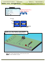
1
Doc. Name: NMC-DC User Manual
Revision: 01
NMC-DC Irrigation
Page: 1 of 38 pages
Farm Management Made Easier
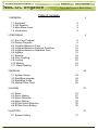
Table of contents
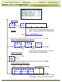
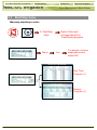
1.GENERAL
1.1 Keyboard
1.2 Hot Screens
1.3 Main Menu Icons
1.4 Introduction
02
02
02
03
04
2.PROGRAM
2.1 Run Time Program
2.2 Dosing Program
2.3 Irrigation Based on Time
2.4 Irrigation Based on External Condition
2.5 Irrigation Based on Radiation Sum
2.6 Agitator
2.7 Selector
2.8 Filter Flushing
2.9 Cooling
2.10 Misting
2.11 Water Heating
05
05
06
12
16
18
19
19
20
22
23
23
3.MANUAL
3.1 System Pause
3.2 Start/Stop program
3.3 Start/Stop Valve
3.4 Manual Filter Flush
24
24
24
25
26
4.ALARM
4.1 Reset
4.2 Alarm History
4.3 Alarm Definition
4.4 Alarm Setting
4.5 EC/pH Alarm Definition
4.6 EC/pH Alarm Setting
27
27
27
28
30
30
30
5.HISTORY
5.1 System History
31
31
Doc. Name: NMC-DC User Manual
Chapter: General
NMC-DC Irrigation
Revision: 01
Page: 2 of 38 pages
Farm Management Made Easier
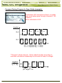
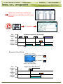
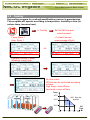
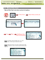
1. GENERAL
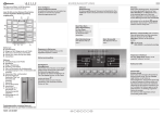
1.1 Keyboard
Numeric- To enter values, quantities. Act as
shortcuts to selections.
+/- Key- Toggles between positive and negative
values and marks check boxes option selection.
In a History screen, use to toggle between
quantities and time format.
Arrows- Scroll up, down, left, and right to select
menus.
MENU- To main menu, also acts as "ESC" and
"Back" keys.
ENTER- Enter menu, submenu, value, open
window, confirm a value or change.
HELP- Access help screens and graphs.
DELETE- Erases typing mistake.
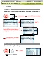
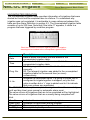
1.2 Hot Screens
Press MENU from Main Menu to see Read-Only overview running
processes. Press MENU again to return to Main Menu.
9 Hot Screens/Keys:
0- Hot Key- Icon of active actions/processes
1- Main Screen/System Status
2- Irrigation Process
3- Irrigation Program Status
4- Water, EC/pH, Dosing
5- Filter Flushing Status
6- Temperature & Humidity measurement
7- Weather Station measurement
8- System Pressure
Doc. Name: NMC-DC User Manual
Chapter: General
NMC-DC Irrigation
Revision: 01
Page: 3 of 38 pages
Farm Management Made Easier
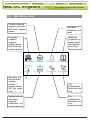
1.3 Main Menu Icons
Conduct manual
irrigation process,
filter flush, system
pause
Programs:
irrigation
regimen,
dosing recipe,
filter flushing,
entire program
Manually test
field devices
(valves,
pumps…),
sensor values
(EC, pH, temp,
hum…)
System set-up,
time/date,
sensors
calibration, unit
measurements
Set alarm
threshold, and
reset
Data logirrigation log,
water meter,
and system
event log
For
professional
technical use
only
For
professional
technical use
only
Doc. Name: NMC-DC User Manual
Chapter: General
NMC-DC Irrigation
Revision: 01
Page: 4 of 38 pages
Farm Management Made Easier
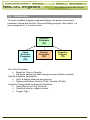
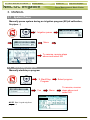
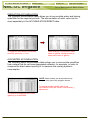
1.4 Introduction
To set an irrigation program-regiment/strategy- the grower must select
necessary valves and set Run Time and Dosing program. May define 1 or
more programs for 1 or more valves.
Irrigation
Programs
(15)
Valve
Run time
Programs
(60)
Dosing
Programs
(10)
Irrigation
Triggers
(15)
Run Time Programs• Based on Time or Quantity
• Set water before and after dosing process (fertilizer injection)
Dosing Programs (fertilization)
• Up to 8 dosing channels per program
• Dosing method per channel (Time, Quantity, EC/pH)
Irrigation Timing based on External Conditions
• Start/ Stop up to 2 Dry Contacts
• Start/End time for irrigation period
• Trigger Type
Doc. Name: NMC-DC User Manual
Chapter: Program
NMC-DC Irrigation
Revision: 01
Page: 5 of 38 pages
Farm Management Made Easier
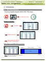
2. PROGRAM
2.1 Run Time Program
For every irrigation program, define a Run Time recipe
2. Water Run Time
Based on Time/Qty:
Time/Qty.
Define Time/Qty.
Define value for "before"
and "after" time program
Water Before and After Dosing process:
Water
2 min
NOTE: Define total Time/Qty. Before and after
deducted from total Time/Qty.
Water + dosing
12 min
Water
1 min
Time
Doc. Name: NMC-DC User Manual
Chapter: Program
NMC-DC Irrigation
Revision: 01
Page: 6 of 38 pages
Farm Management Made Easier
2.2 Dosing Program
For every irrigation program, define a Dosing recipe
3. Dosing
Dosing Channel Definition (Channel mode pre-configured by
technician):
Channel
Define dosing method
for specific channels
(USA: Qty.=gallon)
Proportional Qty. (1/1000, Litre/m³, gallon/1000gallons):
5 liters (gallon) of
fertilizer for every M³
(1000 gallon) of water
Doc. Name: NMC-DC User Manual
Chapter: Program
Revision: 01
NMC-DC Irrigation
Page: 7 of 38 pages
Farm Management Made Easier
Proportional Time:
P. Time
Define minimum dose
for each channel
Irrigation
P1
P2
P3
P4
P5
P6
Time in pulses for
Channel 1 or 2
Ex: Ch 1= P1+P2+P3…+Pn= 10 min.
NOTE: Proportional Time= Take desired dosing time and spread out
dose over irrigation program in open/close pulses per channel.
Time:
Define in 1 bulk: Open
for a set time straight
through, i.e. not spread
out over a defined
program.
Time
Irrigation
5 min
Ex: Ch 3= P1= 5 min. (1 pulse)
Time in bulk
Channel 3
Doc. Name: NMC-DC User Manual
Chapter: Program
Revision: 01
NMC-DC Irrigation
Page: 8 of 38 pages
Farm Management Made Easier
Quantity: (Example shows liters, in USA use gallons.)
Qty.
•
Option A- In Bulk (similar to Time above).
Irrigation
Ex: Ch 1= P1= 4liters.
(1 pulse)
4 liters
Quantity in bulk Channel 1
•
Option B- Spread Out (According to dosing configuration done
by technician).
Irrigation
P1
P2
P3
P4
P5
P6
Ex: Ch 1= P1+P2+P3…
+Pn= 4 litres.
Quantity in pulses
Main Menu
7. Dosing Configuration
Define according to
Bulk or Spread
Back in Dosing Program menu,
define Injection per Dosing
Channel.
Doc. Name: NMC-DC User Manual
Chapter: Program
Revision: 01
NMC-DC Irrigation
Page: 9 of 38 pages
Farm Management Made Easier
Common Dosing Program for Open Fields (example):
Fertilization (EC) amounts are fixed, no matter
how much water goes through (channels 1 &2Passive)
pH is controlled at 5.50
Irrigation
P1
Ch.2
Ch.1
P1
P2
P2
P3
P3
P4
P4
P5
P6
Ch. 1Ö Spread Qty. = 2 liters
Ch. 2Ö Spread Qty. = 5 liters
**Channel 3 (Acid channel) - Pulse width fluctuates according to
controller calculations depending on pH levels to keep it on target.
Irrigation
pH Dosing
by P. Qty.
P1
3 liter Ö 1m³
pH Target = 5.5
P2
P3
Doc. Name: NMC-DC User Manual
Chapter: Program
Revision: 01
NMC-DC Irrigation
Page: 10 of 38 pages
Farm Management Made Easier
Controlled EC/pH based on P.Qty. (example):
Example A-
Example B-
Define dosing program:
Nutrient amount and
desired EC/pH levels
Controlled EC/pH Target
1.5 EC
5.5 pH
Ex. A
Ex. B
5 liters
(gallons)
3 liters
(gallons)
5 liters
5 liters
(gallons)
(gallons)
5 liters
2 liters
(gallons)
(gallons)
Doc. Name: NMC-DC User Manual
Chapter: Program
Revision: 01
NMC-DC Irrigation
Page: 11 of 38 pages
Farm Management Made Easier
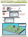
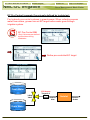
EC Pre-Control (example if previously defined by technician):
For hydraulic pre-control systems in greenhouses: When collecting excess
water from drains, grower can set EC target before water goes through
irrigation system.
EC Pre-Control ON
*Only if this was pre-defined
by technician during
installation.
Define pre-controlled EC target
Fresh Water
EC SensorTarget 0.8
3-Way
Valve
Drain Water
NetaJet
Inlet
NetaJet
NetaJet
Outlet
Doc. Name: NMC-DC User Manual
Chapter: Program
Revision: 01
NMC-DC Irrigation
Page: 12 of 38 pages
Farm Management Made Easier
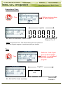
2.3 Irrigation Based on Time
1. Irrigation
Example 1
Select program
Valve
V2
V1
Cycle 2
Cycle 1
Irrigation program for 1 valve
8:00
9:00
NOTE: Min. Time= Delay between cycles from start time to start time
Clock Start= Number of cycles
Valve 1- runs 2 cycles, 1 hour between start
times on Run Time & Dosing Prog. 1
10:00
Doc. Name: NMC-DC User Manual
Chapter: Program
NMC-DC Irrigation
Revision: 01
Farm Management Made Easier
Example 2
Irrigation program for a
group of 2 valves
Valve
V2
V1
Cycle 2
Cycle 1
8:00
Page: 13 of 38 pages
9:00
10:00
Valve 1 & 2- run 2 cycles, 1 hour between
start times on Run Time & Dosing Prog. 1
NOTE: Min. Time= Delay between cycles from start to start
Clock Start= Number of cycles
Doc. Name: NMC-DC User Manual
Chapter: Program
Revision: 01
NMC-DC Irrigation
Page: 14 of 38 pages
Farm Management Made Easier
Example 3
Irrigation program for a
group and individual valve
+
C1= cycle 1
C2= cycle 2
Valve
V3
C1
C2
C1
C2
C1
C2
V2
V1
C1
8:00
C2
9:00
C1
10:30
C2
11:00
C1
12:30
C2
1:30
Time
Valve 1 & 2- runs 6 cycles simultaneously on Run Time & Dosing
Program 1, valve 3 runs after valves 1& 2 on Run time & Dosing
Program 2, different/interchangeable start times.
NOTE: Different/interchangeable delays (multiple start time) dividing the day into periods
NOTE: Min. Time= Delay between cycles from start to start
Clock Start= Number of cycles in every period (start time)
Doc. Name: NMC-DC User Manual
Chapter: Program
NMC-DC Irrigation
Revision: 01
Page: 15 of 38 pages
Farm Management Made Easier
Depending on weather conditions, increase/decrease amount of water
emitted from valves without changing the program.
Example 4
If a lot of radiation, want to
irrigate more, +20%
(Regular 10min. runtimeÖ12 min.)
NOTE: Daily = Current day only. Regular program will resume the following day.
Example 5
If there is bad weather,
want to irrigate less, -10%
(Regular 10min. runtimeÖ9 min.)
NOTE: Const.= Constant running of program on daily basis. May increase/decrease
amount of water in this mode according to weather conditions.
Select water/dosing program by days of week
Example 6
Select program
by days of week
S
X
M
T
X
W
TH
X
F
ST
X
S
D
M
W
T
-
W
D
TH
W
F
-
ST
D
OR
Choose cycle of days
D = Dosing + Water
W = Just Water
- = Nothing
Doc. Name: NMC-DC User Manual
Chapter: Program
Revision: 01
NMC-DC Irrigation
Page: 16 of 38 pages
Farm Management Made Easier
2.4 Irrigation Based on External Condition (Field)
To operate irrigation by peripheral equipment (i.e., filling a water tank
according to level float switch)
4. Ext.
Condition
Set
start/end
time
Select trigger type
Condition On
Input
Off
Irrigation On
Program
Off
Condition On
Input
Off
Irrigation On
Program
Off
Condition On
Input
Off
Irrigation On
Program
Off
Start
Condition
Input
Stop
Condition
Input
On
Trigger Type: One Shot
= 6 sec
Run Time
Run Time
Trigger Type: Multi Shot
Run Time
Run Time
Run Time
Run Time
Trigger Type: Only if ON
Run Time
Run Time
Trigger Type: Stop Dry Con.
Off
On
Off
Irrigation On
Program Off
Run Time
Run Time
Doc. Name: NMC-DC User Manual
Chapter: Program
Revision: 01
NMC-DC Irrigation
Page: 17 of 38 pages
Farm Management Made Easier
Select dry contact (pre-defined by
technician) to start/stop condition and
set limit
1. Irrigation
Start
Condition
Input
Stop
Condition
Input
On
Start/Stop Irrigation by Dry Contact
Off
On
Off
Irrigation On
Program Off
Run Time
Run Time
8:00
Example of tank filling:
Dry contact 2
Dry contact 1
Water Tank with Floats
Start
Condition
Input
Stop
Condition
Input
On
Off
On
Off
Irrigation On
Program Off
Trigger Type: Stop Dry Con.
Doc. Name: NMC-DC User Manual
Chapter: Program
Revision: 01
NMC-DC Irrigation
Page: 18 of 38 pages
Farm Management Made Easier
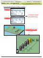
2.5 Irrigation Based on Radiation Sum (Greenhouses)
Set trigger based radiation sum limit Joul/cm²=Energy
1. Irrigation
Set start/end time
Rad. Sum limit
Set min./max. resting time
Select program
NOTE: Start Time= When to begin measuring radiation levels to implement irrigation program.
Min. rest time most important so as to not irrigate too often when radiation levels fluctuate. In
this example, 8:00-10:00 irrigation should occur at most every 30 min. when radiation hits
300joules/cm².Max. rest time here indicates that irrigation must occur at least every hour if there
is less radiation.
Rad. Sum
limit 150
Rad. Sum
limit 300
Irrigation
300
Joules/cm²
150
7:00
8:00
10:00
Irrigation by clock start at 7:00
Irrigation by radiation sum
16:00
Doc. Name: NMC-DC User Manual
Chapter: Program
Revision: 01
NMC-DC Irrigation
Page: 19 of 38 pages
Farm Management Made Easier
2.6 Agitator
To operate fertilizer tanks with mixing devices
5. Agitator
Ö Define On/Off time during dosing and
when system is idle
Ö Select Parallel to operate +1 Agitator
simultaneously
Ö Select Serial if not enough power to
operate +1 agitator at a time
OR
2.7 Selector
+1 fertilizer tank (with different fertilizers) attached to a single dosing
channel
6. Selector
S1
S2
S1
S2
Dos. Chan. 1 / Dos. Chan. 2
Doc. Name: NMC-DC User Manual
Chapter: Program
NMC-DC Irrigation
Revision: 01
Page: 20 of 38 pages
Farm Management Made Easier
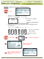
2.8 Filter Flushing
Program filter flushing during irrigation process
7. Filter
Flushing
NOTE: Filter flush process can start only after main
water line is full. Default set at 1 min., see menu 3.3.
NOTE: See graph on next page for further information.
Item
Time Between
Flushing
Flush Time
Delay Between
Filters
Delta Pressure
Delta Pressure
Value (sensor)
Delta Pressure
Delay
Delta Pressure
Reiteration
Dwell Time Main
Description
Time between flushes accumulated during set
irrigation time (one filter flush a time).
Flush time per filter.
Set delay between flushes to build up pressure.
Set flush by pressure sensor. Pressure at filter
inlet/outlet, if there is a significant difference, a filter
may be blocked.
If there is a differential, (DP signal or Analog DP
value), a flush is needed.
Set delay to verify if there is a definite blockage.
Set to give signal after XX flushes. If Delta Pressure
still indicates a blockage, an alarm will be raised.
Open main filter valve before flush to balance
pressure for a reliable flushing process.
Doc. Name: NMC-DC User Manual
Chapter: Program
Revision: 01
NMC-DC Irrigation
Page: 21 of 38 pages
Farm Management Made Easier
Start Time
1 hr
Irrigation
8:00
1 hr
Irrigation
Delay
9:00
10:00
3:00
11:00
After 2 hours of water flowing through
filters, flush every filter for 10 seconds.
Trigger
Flush Process
Trigger
Flush Time/Delay Between Filters
Flush 1
Flush 2
5 sec.
Delay
10 sec.
Dwell Time Main
10 sec.
Dwell
Time
Flush 3
5 sec.
Delay
10 sec.
10 seconds of flushing with 5 second
delay between flushes/filters.
Flush 1…
Delta Pressure Reiteration
DP
Signal
Flush 1
DP
Signal
Flush 2
DP
Signal
Alarm/Stop Flushing
Flush 3
After 3 flushes, if Delta Pressure shows
a blockage, system will raise an alarm.
Doc. Name: NMC-DC User Manual
Chapter: Program
Revision: 01
NMC-DC Irrigation
Page: 22 of 38 pages
Farm Management Made Easier
2.9 Cooling
Set cooling program for cooling/humidification process in greenhouses.
This program will operate according to temperature, humidity or time (to
reduce temp, increase hum.)
8. Cooling
Temp. Sens. 1
Hum. Sens. 1
Set On/Off time and
select sensors
+1 of each sensor:
uses average of both
OR
Dynamic cooling: 2 temp.
threshold, same Hum.
On time is set.
Off time can be controlled according
to temp.
High temp.= less off time
Low temp.= more off time
Temp.
V1
V2
35°C
80%- Stop the
process
30°C
25°C
Off
Time
2.5
5
7.5
10
12.5
Doc. Name: NMC-DC User Manual
Chapter: Program
Revision: 01
NMC-DC Irrigation
2.10
Page: 23 of 38 pages
Farm Management Made Easier
Misting
General program using a timer
9. Misting
Ö Define Start/End time
Ö Define misting On/Off time
2.11
Water Heating
Heat water in cold areas/seasons
10. Water
Heating
Ö Define Start/End time
Ö Define Water Temp. ± Difference (dead band) to stop
Ö Define sensors
ON /OFF
Cold
Hot
16
18
20
Temperature
22
24
°C
Doc. Name: NMC-DC User Manual
Chapter: Manual
Revision: 01
NMC-DC Irrigation
Page: 24 of 38 pages
Farm Management Made Easier
3. MANUAL
3.1 System Pause
Manually pause system during an irrigation program (EC/pH calibration,
fix pipes…)
1. Irrigation pause
Menu
To resume, reverse steps
above and select NO
3.2 Start/Stop program
Manually start/stop a program
2. Start/Stop
Program
Yes
NOTE: Start 1 cycle only from
program 1
Menu
Select program
To resume, reverse
steps above and
select NO
Doc. Name: NMC-DC User Manual
Chapter: Manual
NMC-DC Irrigation
Revision: 01
Page: 25 of 38 pages
Farm Management Made Easier
3.3 Start/Stop Valve
Manually start/stop a valve
3. Start/Stop
Valve
Menu
Select Valve and
corresponding Run
Time/Dosing program
Yes
To resume, reverse
steps above and
select NO
Run Time
Program (1)
Dosing
Program (1)
Doc. Name: NMC-DC User Manual
Chapter: Manual
NMC-DC Irrigation
Revision: 01
Page: 26 of 38 pages
Farm Management Made Easier
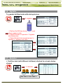
3.4 Manual Filter Flush
Manual filter flush only when system is irrigating
4. Filter Flush
Yes
Menu
Hot Screen 5 to
view flushing status
NOTE: "All Filters" means all filter's but 1 at a time.
No more than 1 filter may be flushed at a time.
NOTE: Filter flush process can start only after main water
line is full. Default is 1min. as shown in picture below (See
menu 3.3
Select filters (usually all)
Doc. Name: NMC-DC User Manual
Chapter: Alarm
NMC-DC Irrigation
Revision: 01
Page: 27 of 38 pages
Farm Management Made Easier
4. ALARM
4.1
Reset
Reset alarm (in case of high flow, low flow, water leak, fertilizer leak…)
1. Alarm Reset
Option A: Reset manually
Yes
Option B: Automatic reset to check
itself every so often as desired:
Ö Select how often system should
reset itself
"Complete Irrig. On Reset?"
Select Yes or No
4.2
Alarm History
View alarm history (Read-Only)
2. History
NOTE: Logs up to 250 alarms
Doc. Name: NMC-DC User Manual
Chapter: Alarm
NMC-DC Irrigation
4.3
Revision: 01
Page: 28 of 38 pages
Farm Management Made Easier
Alarm Definition
Define system threshold
3. Alarm Definition
Define trigger: deviation from
target pressure, flow…
Item
Water Fill Up
(min)
Water Leak (m3
or Gal)
Water Leak
Period (hh:mm)
Identify LeakSubtr. Meter?
Dosing Channel
Leak Delay (s)
Dosing Channel
Leak (Pulse)
Dosing Flow
Difference (%)
Description
Time of filling the main irrigation line. In that time, the
system will ignore high flow alarm and won't
implement a filter flushing process.
Quantity of water leaking while the system is in idle.
Time frame to measure the water leak quantity
Example; 1m3 was leaking in less than 30min.
This setting relevant only when working in "Water
source" method. User can ignore or identify a water
leak.
Delay between switching off a dosing channel and
generating dosing leak alarm.
Number of pulses (by dosing meter) during the delay
above to generate an alarm. Example; 10 pulses in 3
seconds will generate alarm.
Difference between calculated and measured dosing
channel flow. Example; Dosing Channel 1 defined by
technician as 100liter/hour, but if the system
measured less than 75liter/hour or more than
125liter/hour, an alarm will be generated.
Doc. Name: NMC-DC User Manual
Chapter: Alarm
NMC-DC Irrigation
Revision: 01
Page: 29 of 38 pages
Farm Management Made Easier
Table continued…
Item
Missing Pulses
For No Flow
Stop System
Consecutive Flow
Alarms
# of Irrigations
Without Drainage
Low Pressure
Alarm (bar/psi)
Num. Of Short
Circ. To Pause
Short Output
Level (60-350)
Short O. Level
EXT1 (60 – 350)
Short O. Level
EXT2 (60 – 350)
Short O. Level
EXT3 (60 – 350)
Description
Number of missing pulses before the system will
generate a No Flow alarm. The system calculates the
expected time between pulses of water meter and if a
certain time elapsed without receiving the desired
number of pulses, then generate an alarm.
Number of consecutive flow alarms of the same type
(high flow, low flow etc’) but different valves before the
system is stopped. Example; High flow at valve 1 >High flow at valve 2->High flow at valve 3 = 3
consecutive High flow, then system stops.
Number of irrigations given without measuring
drainage, above which an alarm will be generated.
Common reasons: Irrigation quantity is too small so
there is not enough drain, or drain measurement
malfunction because of technical problem.
Minimum system pressure before generate an alarm.
Number of short circuit (in field device) alarms
measured before the system is paused.
Define the A/D threshold value to be considered as a
short circuit (For technician use only).
Define the A/D threshold value to be considered as a
short circuit for Extension box no. 1 (For technician
use only)
Define the A/D threshold value to be considered as a
short circuit for Extension box no. 2 (For technician
use only)
Define the A/D threshold value to be considered as a
short circuit for Extension box no. 3 (For technician
use only)
Doc. Name: NMC-DC User Manual
Chapter: Alarm
NMC-DC Irrigation
4.4
Revision: 01
Page: 30 of 38 pages
Farm Management Made Easier
Alarm Setting
Set alarms and define action in event of an alarm
4. Alarm Setting
Ö Define alarm action: automatically
stop or continue.
Ö Delay before generating alarm.
Ö Alarm output activation: YES/NO (siren, light).
4.5
EC/pH Alarm Definition
Define EC/pH threshold
5. EC/pH Alarm
Definition
Ö Delta Low: Maximum differences
bellow EC, pH and EC Pre-Control targets.
Ö Delta High: Maximum difference above EC, pH and
EC Pre-Control targets.
Ö Emergency: Critical values of High EC and Low pH
that stop the system after 1min.
4.6
EC/pH Alarm Setting
Set EC/pH alarm and define action in event of an EC/pH alarm
6. EC/pH Alarm
Setting
Ö Define EC/pH alarm action: automatically stop or continue.
Ö Delay before generating alarm.
Ö Alarm output activation: YES/NO (siren, light).
Doc. Name: NMC-DC User Manual
Chapter: History
Revision: 01
NMC-DC Irrigation
Page: 31 of 38 pages
Farm Management Made Easier
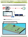
5. HISTORY
5.1
System History
Read-Only screens of system's history (measurements, settings,
processes, events, graphs…)
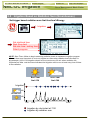
11. Sensor
Log
Select sensors using +/- key
(no more than 3 per graph)
Menu
NOTE: Use ×Ø arrow keys to zoom in/out.
Use ÕÖ arrow keys to scroll.
Doc. Name: NMC-DC User Manual
Chapter: History
NMC-DC Irrigation
Revision: 01
Page: 32 of 38 pages
Farm Management Made Easier
The history menu provides extensive information regarding
measurements and processes performed by the NMC-DC.
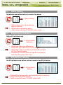
IRRIGATION LOG
The Irrigation Log table includes up to 200 rows of the last irrigations' data.
Each row includes information regarding a specific irrigation.
To view additional information, use the left/right arrow keys.
To switch between dosing quantities or time simply press the ‘+/-‘ key.
NOTE: Water quantity is measured in m³
or gallons; duration is measured by time;
flow is measured in m³/h or gallon/m;
dosing quantity is measured in liters or
gallons.
Item
Date
Time
Valve
Reason
Water
Duration
Flow
Chan. #
EC Low
EC Avg.
EC High
pH Low
pH Avg.
pH High
Description
Date in which the irrigation started.
Time in which the irrigation started.
Leading valve; the first valve set for the group of valves
Specification of the irrigation triggers; time, condition, Rad
Sum, etc.
Irrigation quantity (m³ or gallon) or irrigation time.
Irrigation duration (hh:mm:ss).
Average flow throughout the irrigation cycle.
Dosing quantities per channel (liter or gallon) or dosing time.
Lowest EC value recorded during irrigation.
Average EC value recorded during irrigation.
Highest EC value recorded during irrigation.
Lowest pH value recorded during irrigation.
Average pH value recorded during irrigation.
Highest pH value recorded during irrigation.
Doc. Name: NMC-DC User Manual
Chapter: History
NMC-DC Irrigation
Revision: 01
Page: 33 of 38 pages
Farm Management Made Easier
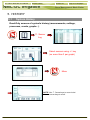
RAD. SUM & DRAIN LOG
Item
Time
Valve
Reason
Water
Drain %
Drain
Rad Sum
Interval
Description
Time irrigation started.
Leading valve.
Specification of the irrigation triggers; time, condition, Rad
Sum, etc.
Irrigation quantity (m³ or gallon) or irrigation time.
Percentage of drain for relevant irrigation cycle.
Drain quantity related to relevant irrigation.
Accumulated radiation sum level when irrigation started.
Time (in minutes) since last irrigation cycle. Refers to the last
irrigation of a specific valve.
Doc. Name: NMC-DC User Manual
Chapter: History
NMC-DC Irrigation
Revision: 01
Page: 34 of 38 pages
Farm Management Made Easier
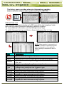
UNCOMPLETED IRRIGATION
The Uncompleted Irrigation table provides information of irrigations that were
started but could not be completed due to a failure. To understand why
irrigation was not completed, it is advisable to cross-reference between this
table and the Alarm Definition in section 4.3. The Uncompleted Irrigation table
consists of up to 200 lines. Note that if the letter 'C' appears, it refers to a
program that was triggered by condition program.
Each line includes information regarding when the irrigation
was stopped and added to the uncompleted irrigations table.
Item
Description
Date in which the current line was added to the
Date
uncompleted irrigation table.
Time in which the current line was added to the
Time
uncompleted irrigation table
92- The program that was added to the table was started
manually.
Prog. No.
93- The relevant irrigation was added to the uncompleted
irrigations table for the second time (or more)
consecutively.
Indicates the associated valve. If a group of valves that is
configured to irrigate together is stopped, only the first
Vl. No.
valve is written but a ‘+’ sign is added next to it to indicate
that more valves are associated.
The NMC-DC will attempt to complete the irrigations from the current day
(until end day time) upon manual or automatic alarm reset.
The valve column of irrigations that are to be completed will be highlighted.
The valve column of irrigations that are currently being completed will
blink.
Run No
Dose Prog.
Prog. Qty.
Left Qty.
Indicates the associated run time program.
Indicates the associated dosing program.
Planned quantity according to the run time program.
Uncompleted quantity.
Doc. Name: NMC-DC User Manual
Chapter: History
Revision: 01
NMC-DC Irrigation
Page: 35 of 38 pages
Farm Management Made Easier
In order to manually stop an uncompleted irrigation you must go to the
START/STOP VALVE in section 3.3 because the activation is according to
single valves.
UNCOMPLETED PROGRAMS
The Uncompleted Programs table provides information on programs that could
not be completed. It is important to understand the difference between this
table and the Uncompleted Irrigations table; this table consists only of
irrigation cycles that haven’t been started and could not be completed during
the current day. This can happen due to wrong system setup (more tasks than
could be completed), or because the system was not active for a long period
of time, for example due to a power failure, and could not complete its tasks.
The uncompleted program
table consists of 200 lines.
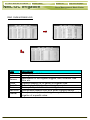
DAILY IRRIGATION
This table allows you to view history of irrigation quantities or time per valve.
Example: 1 day ago means
you would like to view
yesterday's history, and Today
means you would like to view
the accumulated history since
the last End Day.
To open the
selection list
Current date viewed at top of screen.
Relevant day
using arrow
keys
ENTER
Daily Irrigation table contains all water (m3 or gallon)
and dosing (liter or gallon). To toggle the view
between quantities and time, press the ‘+/-‘ key.
Doc. Name: NMC-DC User Manual
Chapter: History
NMC-DC Irrigation
Revision: 01
Page: 36 of 38 pages
Farm Management Made Easier
IRRIGATION ACCUMULATION
The Irrigation Accumulation table allows you to accumulate water and dosing
quantities for the required periods. The accumulation of each valve can be
reset separately in the ACCUMULATION RESET table.
To toggle the view between quantities
and time, press the ‘+/-‘ key
Water quantity is measured in cubic
meter or gallons; dosing quantity is
measured in liters or gallons.
AUX METER ACCUMULATION
The Auxiliary Meter Accumulation table allows you to accumulate quantities
from meters that do not have designated software, for example, in order to
measure the drain water quantity or to measure the cooling system’s
consumption.
NOTE: Water meters are accumulators only
and are not a part of the irrigation control.
To reset an auxiliary meter refer to the
ACCUMULATION {XE "Reset Total Quantity" }
table below.
The quantities displayed are in liters
(gallons) up to 9999.999.
Doc. Name: NMC-DC User Manual
Chapter: History
Revision: 01
NMC-DC Irrigation
Page: 37 of 38 pages
Farm Management Made Easier
ACCUMULATION RESET
ENTER
ENTER to reset
accumulation of a
specific valve or all
valves
Desired option
using arrow keys
NOTE: When resetting a valve (or all valves), its history will be erased from the following tables:
-Daily Irrigation
-Irrigation Accumulation
ENTER to reset an
individual auxiliary
meter or all auxiliary
meters
Desired option
using arrow keys
ENTER
NOTE: When resetting an Aux meter (or all Aux meters), its history will be erased from the Aux
Meter Accumulation table.
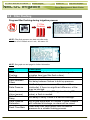
FILTERS
The filters history table provides daily information of the number and cause of
flushing.
COOLING
Viewing the history of cooling activities or time per valve is allowed.
ENTER
ENTER to open
selection list
Relevant day
using arrow keys
For example, 1 day ago means you would like to view
yesterday's history, and Today means you would like to
view the accumulated history since the last End Day.
Doc. Name: NMC-DC User Manual
Chapter: History
NMC-DC Irrigation
Revision: 01
Page: 38 of 38 pages
Farm Management Made Easier
SENSOR LOG
The sensors Log table includes history of average measurements of logged
sensors. In order to define which sensor to log, the user should access menu
6.8 – Sensor Logging, and mark by +/- button the required sensor.
In order to define the measurement interval, the user should go to menu 6.2
and choose the required History resolution.
The sensors Log table contains up to 10,000 data fields. Date and time are 2
fields per line and every sensor is an additional field.
For example: logging of 2 sensors uses 4 data fields; 2 for time and date and
1 for each sensor. In this case, the table will consist of a maximum of 2,500
lines.
EVENT LOG
The table provides information of all the processes performed by the NMC-DC
including their time and date.
The table consists of the last 999 events.
SYSTEM LOG
This table provides information of all the system changes.
The table consists of the last 999 events.
Examples of system changes are changes of triggered by the controller, the PC
communication, a power off, etc.
Main Battery LOW = 11.7 Volts
System In Idle Mode = under 11.7 Volts (Valves are closed)
Emergency Power Down = Main Battery drops to 11.2 Volts (Controller is OFF)