1
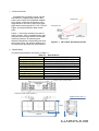
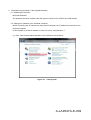
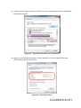
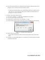
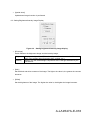
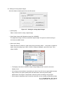
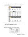
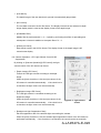
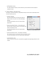
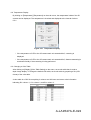
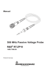
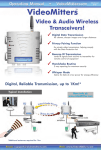
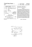
User Manual
ZA1 Type 3D Camera
LA9547A
Ver. 2.0
The Nippon Signal Co., Ltd.
Visionary Business Center
MEMS Promotion Dept.
Nippon Signal Co., Ltd.
A-LA9547A-E-001
Table of Contents
1. Product Overview ...........................................................................................................................6
2. Specifications .................................................................................................................................6
3. Main unit/Accessories ....................................................................................................................7
4. Preparation .....................................................................................................................................8
4.1
Mounting ..............................................................................................................................8
4.2
Demounting ..........................................................................................................................8
5. Preparation and Activation of the Supplied Software ......................................................................9
5.1
Operating Environment ........................................................................................................9
5.2
Setting an IP Address of the Personal Computer .................................................................9
5.3
Activation of the Sample Display Software .........................................................................12
6. Operation Procedure of the Supplied Software ............................................................................13
6.1
Starting/Stopping Image Generation ...................................................................................14
6.2
Setting Display of a Depth Image .......................................................................................14
6.3
Setting Brightness/Intensity Image Display ........................................................................16
6.4
Setting for Saving Depth Images ........................................................................................17
6.5
Playing Back Recorded Data..............................................................................................19
6.6
Camera Operation-LED Light Volume Control & BG Suppression ...................................20
6.7
Camera Operation-Depth Map Control ............................................................................21
6.8
Temperature Display ..........................................................................................................22
6.9
Changing a Color Table ......................................................................................................22
6.10
Camera Setting ..................................................................................................................23
6.11
Network Setting ..................................................................................................................24
A-LA9547A-E-002
Precautions
To use this product effectively, read all the contents relating to the product you have purchased
before using it.
Since this manual contains important information for using this product, keep this manual at hand so
that you can verify the information as required.
Safety Precautions
This manual provides a number of pictograms in order to prevent any harm to the customers, other
people, or property damage by ensuring the correct safe use of this product. The pictograms and the
meanings are provided below. Familiarize yourself with the contents before reading the main text.
If this product is handled incorrectly, ignoring this sign, a
serious injury could occur.
If this product is handled incorrectly, ignoring this sign, a
serious injury and property damage may occur.
Example of pictograms
Invokes a caution (including warning).
A caution is necessary.
Indicates that the behavior is prohibited.
Prohibited.
Indicates that the action is forced or directed.
The action is mandatory.
A-LA9547A-E-003
While operating the 3D camera, do not look through the glass window of
the LED 3D emission surface. Doing so may harm the eyes.
Do not use the product with the voltage other than the specified power
supply voltage. Doing so causes a fire or an electric shock.
Turn off the power supply as soon as detecting smoke or any strange
odor.
When detecting smoke, wait until verifying that smoke is no longer
generated from the product and then request for repair. Never carry out
repair by yourself as it is dangerous.
A-LA9547A-E-004
Vibration and impact
Do not apply strong vibrations or impact such as dropping this product.
If this product is dropped on a floor, the product can no longer be
guaranteed.
Since this product uses precise optical elements, mechanical vibrations
and impacts may damage the product, causing performance deterioration.
Handle the glass window with care since it is particularly fragile.
Environment condition
Do not leave this product in a location that is exposed to condensation or
a corrosive gas.
Property degradation may occur due to the environment conditions.
Wiring
If this product is used incorrectly such as with incorrect wiring, connector
insertion error, or use of the product outside of the specified ratings, the
performance may not be exerted or the product may be destroyed.
Disassembly
Disassembling this product may cause performance degradation or
destruction of internal parts. If this product is disassembled, the product
can no longer be guaranteed.
Caution on cleaning method
If normal performance is impaired by the dirty glass window, clean the
window by gently wiping it with a clean soft cloth such as cotton swab or
gauze moistened with reagent ethanol (ethyl alcohol). Do not clean any
parts other than the glass window.
Duplication, transcription, distribution, and alteration of a part or the entire
contents of this manual or other documents, electronic data, and programs
that belong to the product are prohibited.
Copying or production of a similar item to this product is prohibited.
Please note that the contents of this manual are subject to change without
prior notice.
A-LA9547A-E-005
1. Product Overview
PixelSoleil ZA1 (refered to as 3D camera
henceforth) is a depth image camera that
emits near infrared LED modulated radiation
to the space, measures the distance to the
target based on the time of light return flight
(flight time measuring method = TOF: Time Of
Flight), and outputs distance data of each
point.
Figure 1.1 shows the operation principle of
the 3D camera. LED is radiated and the light
reflected from the target enters into the light
receiving elements. By measuring the
difference between the transmitting time and
the receiving time, the distance between the
3D camera and the target can be measured.
Ambient light
LED light source
Condensing
lens
Depth
measuring area
CMOS sensor
Figure 1.1 3D camera operation principle
2. Specifications
3D camera specifications are shown in Table 2.1.
Table 2.1 Specifications
Detecting range
0.3 - 4m H72° x V72°
Image resolution / Frame rate
126 x 126 / 30fps
Ranging accuracy
+/-130mm (2m/reflection rate30%)
Dimensions / Weight
W188 x H70 x D65mm / about 850g
Ambient light resistance
100,000lx
IP ratings
IP65
Operating temperature
-10 - 50°C
Storage temperature
-20 - 70°C
Supply voltage
DC12 - 24V
Power consumption
18W or less
Data interface
Ethernet(TCP/IP)
Power (JAE JN1FS10SL1)
Ethernet (JAE JN1FS10SL1)
tapped hole (M4 x 4)
70mm
188mm
65mm
A-LA9547A-E-006
3. Main unit/Accessories
(1) 3D camera main unit
(2) AC adaptor
(3) Power supply cable
(4) Communication cable
(5) Supplied CD
The folder configuration and the contents of the supplied CD are as follows.
• User Manual
• Communication Interface Specification
• English version sample display software
• Japanese version sample display software
• Run time module for executing sample display software
Separated into the Japanese version and the English
version in the subfolder.
A-LA9547A-E-007
4. Preparation
4.1 Mounting
Connect the power supply cable and the communication cable to the 3D camera at the
orientations that are shown in Figure 3.1
POWER
Figure 4.1 Cable connection
Connect the supplied AC adaptor to the end of the power supply cable.
When the AC adaptor is connected to the AC outlet, power is supplied to the 3D camera.
4.2 Demounting
When turning off the power supply of the 3D camera, remove the AC adaptor from the outlet.
When removing the cable from the 3D camera, pull out the connector by twisting the locking unit.
Locking unit
Figure 4.2 Removing the table
A-LA9547A-E-008
5. Preparation and Activation of the Supplied Software
5.1 Operating Environment
Microsoft Windows7
The operation has been verified under the system of Intel Core i5 2.5GHz and 2GB memory.
5.2 Setting an IP Address of the Personal Computer
Before connecting the 3D camera and the personal computer, the IP address must be set on the
personal computer.
In this example, a private IP address of class C is set by using Windows 7.
(1) Click “View network status and tasks” on the Windows control panel.
Figure 5.1 Control panel
A-LA9547A-E-009
(2) Click on “Local Area Connection”.
Figure 5.2 Local area connection
(3) Click on “Properties”.
Figure 5.3 Status of the local area connection
A-LA9547A-E-010
(4) Click on “Internet Protocol Version 4 (TCP/IPv4)” of the General tab and click on [Properties]
button below the item.
Figure 5.4 Properties of the local area connection
(5) Select “Use the following IP address”. Enter [192.168.0.1] in the IP address field. Enter
[255.255.255.0] as the subnet mask.
Figure 5.5 Properties of IPv4
A-LA9547A-E-011
(6) Close the window by clicking on the [OK] button and complete the setting by clicking on the
[OK] button of the “Local Area Connection Properties” window.
* To connect the personal computer to the network different from this 3D camera (in-house
LAN, Internet, etc.) after changing the setting of the IP address as indicated above, set
according to the network environment.
5.3 Activation of the Sample Display Software
(1) Copy the “PS_Viewer(E)_v3.1” folder from the supplied CD to any location.
(2) Turn on the power supply of the 3D camera.
(3) Double-click PS_Viewer.exe in the “PS_Viewer(E)_v3.1” folder.
(4) On the network connection window, check that connection destination IP is [192.168.0.80].
Figure 5.6 Connection with the 3D camera
(5) Click on the [Connection] button.
* To start software independently without connecting the 3D camera, click on the [Close]
button.
(6) Preparation for acquiring depth images is now completed. The software operation procedure
is described subsequently.
A-LA9547A-E-012
6. Operation Procedure of the Supplied Software
5
1
2
3
6
7
4
Figure 6.1 Screen structure of the supplied software
Depth image display area
Brightness/intensity image
display area
Image generation start/stop
button
Depth image display setting area
Brightness/intensity display
setting area
Depth image storage setting area
Saved data playback setting area
Displays the depth image that is acquired from the 3D
camera.
Displays the brightness/intensity image that is acquired
from the 3D camera.
Starts/stops image generation.
Sets various parameters for displaying the depth image.
Sets various parameters for displaying the
brightness/intensity image.
Stores the depth image.
Plays back the depth image that has been saved.
A-LA9547A-E-013
6.1 Starting/Stopping Image Generation
Acquire an image from the 3D camera.
Figure 6.2 Monitor button
• [Monitor] button
When this button is clicked on, image generation starts and the button display changes to
[Stop].
• [Stop] button
When this button is clicked on, image generation stops. The button display changes to
[Monitor].
* The Frame rate of the Depth Image Control is 10 FPS. (The depth image from the 3D
camera is loaded into the PC at the interval of 200 ms.)
6.2 Setting Display of a Depth Image
Set the display method of the depth image that is acquired from the 3D camera.
Figure 6.3 Depth image display setting
A-LA9547A-E-014
• [Drawing Mode]
Switch the depth image display mode in the list.
3D color pointillism
2D Color
Performs 3D pointillism while expressing the distance with color.
Performs 2D display while expressing the distance with color.
* In color display, the distance values are displayed by mapping in the color table of 256
colors. For the color table, 256 colors are specified in “TCS_DefColor.csv” in the same
folder as PS_Viewer.
• [Distance Display Range]
Specify the maximum value and the minimum value of the display range in m units.
For color display, the range from the minimum value to the maximum value is mapped in the
color table of 256 colors.
• [Center]
Specify a distance value that becomes the center at the Y-axis rotation in m units.
• [Y-Rot]
Specify the angle of rotation around the Y axis.
When the “Auto” check box is set to ON, the image automatically rotates within the range from
-60° to 60° around the Y-axis during depth image generation.
• [X-Rot]
Specify the angle of rotation around the X axis.
When the “Auto” check box is set to ON, the image automatically rotates within the range from
-60° to 60° around the X-axis during depth image generation.
• [Cam_Position]
“Near” increases the image size. “Far” reduces the image size.
• Binning
Select whether binning processing is performed within the 3D camera.
None
2×2
4×4
•
Binning is not performed
Averaging is performed with 2 adjoining pixels.
Averaging is performed with 4 adjoining pixels.
Mirror inversion]
Left/right image inversion is performed.
A-LA9547A-E-015
• [Upside down]
Upside down image inversion is performed.
6.3 Setting Brightness/Intensity Image Display
Figure 6.4 Setting brightness/intensity image display
• [2D Image]
Switch between the brightness image and the intensity image.
Brightness
Intensity
Displays the light of the LED irradiated by the 3D camera and the reflected
light of the ambient light (fluorescent light, sunlight, etc.).
Display only the reflected light components of the LED light irradiated by the
3D camera.
• [Gain]
Set the black and white contrast of the image. The higher the value is, the greater the contrast
becomes.
• [Offset]
Set the brightness of the image. The higher the value is, the brighter the image becomes.
A-LA9547A-E-016
6.4 Setting for Saving Depth Images
Save the distance data acquired from the 3D camera.
Figure 6.5 Setting for saving depth images
• [Folder path]
Select a folder used for saving a depth image.
• [Save Depth Image with Brightness Image (for AVI/BMP)]
The brightness image is saved as well as the depth image. This option is valid for saving in
AVI format and BMP format.
• [Movie (AVI) Save]
When this button is clicked on, depth image save processing starts.
If the button is clicked on
again, save processing stops. When “Save As” dialog is displayed, enter a file name. Then,
select CODEC.
Figure 6.6 Selection of CODEC
* The display mode that is selected in depth image display mode is used for the movie
display format.
* If the image is saved without compressing, the size of the AVI file to be generated becomes
large, however, the picture quality does not deteriorate. Since the picture quality
deteriorates if the image is compressed, select the option accordiing to the purpose.
* Since distance data (large size) is stored in the buffer once by creating a [TempSave] folder
A-LA9547A-E-017
under the folder and the data is converted to the movie in AVI format by compressing the
data, greater HDD space is required than the actual size of the file that is used. Therefore,
when using the movie saving function, check that the disk of the PC has sufficient free
capacity.
* When a movie is saved under AVI format, the image displayed on the screen is
compressed and saved in AVI format as it is, the depth information of the depth image will
be lost. When performing image processing by using depth information, save the data
under [RawData(.tc4) format].
• [RawData(tc4) Save]
When this button is clicked on, the raw data of the depth image that is being monitored is
saved in binary format. In RawData(.tc4) format, the entire information of depth, brightness,
and intensity is saved, and the image can be displayed in three-dimensional format by loading
the PS_Viewer.exe software.
* The depth image is not displayed while the raw data is being saved.
* Raw data is saved in the folder that was specified in the “Folder path” by assigning a file
name automatically. Note that no dialog is displayed, unlike the AVI format.
* Since a large volume of data is saved, the number of frames that are saved in one .tc4 file
is limited to 10000 frames.
The file name will be as follows.
Year-month-day_hour-minute-second_msec.tc4
Example: Data is saved on May 1,2014, hour 20, minute 34, second 34, 111.
20140501_203434_111.tc4
• [Picture(BMP) Save]
When this button is clicked on, the image that is displayed in the display area is saved in BMP
format. When the “Save As” dialog is displayed, save the name by entering a file name.
• [CSV (ASCII) Save]
When this button is clicked on, the image that is displayed in the display area is saved in CSV
format.
* In CSV format, the image is saved in the folder that is specified in [Folder path] by
assigning a file name automatically. Note that no dialog is displayed, unlike the BMP format.
The file naming rule is the same as for raw data (tc4 format).
A-LA9547A-E-018
• CSV file format
Data is listed in 128 columns x 128 rows in the order of distance data, brightness data, and
intensity data from the top.
The unit of the distance data of the CSV file is digit. Convert the unit to metrics based on the
following formula.
Distance value [m]=15 × distance value [digit] ÷ 16384
6.5 Playing Back Recorded Data
Saved raw data (tc4 format) can be played back.
Select the file to be played back by selecting [File]-[Open] on the menu.
Figure 6.7 Playing back recorded data
A-LA9547A-E-019
• [Auto Movie]
The depth image of the raw data that is opened is automatically played back.
• [AVI convert]
The raw data is saved in the AVI file format. The display format that was selected in depth
image display mode is used as the display format of the depth image.
• [3D Median Filter]
Median filter is performed with 3 × 3 × 3 pixels by performing time filter for preceding and
subsequent 3 frames in addition to the space filter of 3 × 3.
• [2DGray-AVI Save]
Raw data is saved in the AVI file format. The display format of the depth image is 2D
monochrome display.
6.6 Camera Operation-LED Light Volume Control & BG
Suppression
By clicking on [Camera Operation]-[LED Control], the light
volume control of the 3D camera can be set.
• [Depth Image LED Power]
Control the LED light volume according to the depth
image.
When the [Auto] check box is ON, the light volume of the
3D camera is controlled automatically.
If the check box is
unchecked, the light volume can be set manually.
• [Brightness Image LED Power]
The LED light volume is controlled according to the
brightness image.
When the [Auto] check box is ON, the light volume of the
3D camera is controlled automatically.
If the check box is
Figure 6.8 Light volume
control
unchecked, the light volume can be set manually.
• [Background Light Suppression Rate]
Set the suppression rate of the ambient light surrounding the camera.
When the [Auto] check box is ON, the ambient light suppression control of the 3D camera is
performed automatically.
If the check box is unchecked, the control can be set manually.
A-LA9547A-E-020
• [LED Modulation Clock]
The LED modulation frequency can be selected to prevent interference when multiple 3D
cameras are used.
6.7 Camera Operation-Depth Map Control
By clicking on [Camera Operation] – [Depth Map Control] on the main menu, depth image control
of the 3D camera can be set.
• [Intensity Trimming]
Set the threshold value of the function that clips the
distance value of the pixel of low LED reflected light
intensity.
For the function details, refer to the Communication
Specification.
• [Smart Accumulation Function – Accumulation rate]
Set the number of times the frame is accumulated in the
Smart Accumulation function.
For the function details, refer to the Communication
Specification.
Figure 6.9 Depth image control
• [Smart Accumulation function – Accumulation Threshold]
Set a threshold value for executing the Smart Accumulation function.
For the function details, refer to the Communication Specification.
• [Use MedianFilter (HW)]
When the check box is set to ON, a median filter is applied to the depth image inside of the 3D
camera.
A-LA9547A-E-021
6.8 Temperature Display
By clicking on [Temperature]-[Temperature] on the main menu, the temperature inside of the 3D
camera can be displayed. The temperature is checked and displayed at the interval of about
0.5 s.
Figure 6.10
Temperature display
* If the temperature of LED or the 3D camera main unit exceeds 80°C, a warning is
displayed.
* If the temperature of LED or the 3D camera main unit exceeds 85°C, distance measuring is
terminated forcibly if the measuring is being performed.
6.9 Changing a Color Table
After clicking on [Display]-[Color Table Setting] on the menu, set a color table that is used at
depth image display. To change the default color table, set a color table by preparing a file (CSV
format) of the color table.
A color table is a CSV file comprising 3 columns and 256 rows and stores color information
indicating R in column 1, G in column 2, and B in column 3.
A-LA9547A-E-022
6.10
Camera Setting
By clicking on [Camera Operation]-[Camera Setting] on the main menu, time information of the
3D camera can be set.
Figure 6.11
Camera setting
• [Date and Time Acquisition]
The time of the 3D camera can be set. The PC time can be acquired by pressing the [PC]
button. When the [Camera] button is pressed, the time of the 3D camera is acquired. When
the [Set] button is pressed, the time that is displayed is set in the 3D camra.
• [LED indiator settings]
The ON/OFF time of the indicator can be set. When the [Initialize] button is pressed, the
ON/OFF time of the LED is set to the initial value.
Set each value in the unit of 100ms. The function of each color is shown below.
Red
Yellow
Green
Lit at the occurrence of an error.
Lit when the LED is emitted.
Lit when the 3D camera and the PC are connected.
• [LED Emission control temperature]
When the temperature reaches the set temperature or higher, the temprature rise is prevented
by controlling the LED light volume.
A-LA9547A-E-023
6.11
Network Setting
By clicking [Camera Operation]-[Network Connection] on the main menu, the connection between
the 3D camera and the PC can be set.
Figure 6.12
Network connection
• [IP Setting]
To connect the 3D camera and the PC, press the [Connection] button. The button display
changes to [Disconnection]. To disconnect the connection between the 3D camera and the PC,
press the [Disconnection] button.
To use the application only without connecting the 3D camera and the PC, press the [Close]
button.
A-LA9547A-E-024
MEMS Promotion Dept.
Visionary Business Center
THE NIPPON SIGNAL CO., LTD
Head Office
1-5-1 Marunouchi, Chiyoda-ku, Tokyo 100-6513 Japan
Phone: +(81)3-3217-7167
FAX: +(81)3-3217-7377
2014.7.8
A-LA9547A-E-025