1
Industrial
Workstation (WCI)
User Manual for
HE693WCIxxx
12-12-97
MAN0098-02
Page iii
PREFACE
PREFACE
Page iv
PREFACE
This manual explains how to use the Horner APG Industrial Workstation - Controller - Interface
(WCI) for use in industrial environments.
Copyright (C) 2002 Horner APG, LLC., 640 North Sherman, Indianapolis Indiana 46201-3899.
All rights reserved. No part of this publication may be reproduced, transmitted, transcribed, stored
in a retrieval system, or translated into any language or computer language, in any form by any
means, electronic, mechanical, magnetic, optical, chemical, manual or otherwise, without the prior
agreement and written permission of Horner APG, LLC.
Information in this document is subject to change without notice and does not represent a
commitment on the part of Horner APG, LLC.
Genius and Series 90 are trademarks of GE Fanuc Automation North America Inc.
PS/2 is a trademark of IBM Corporation
MS-DOS, Microsoft, and Windows are trademarks of Microsoft Corporation
Appreciation to GE Fanuc Automation and Intel Corporation for the right to incorporate documentation segments authored by them into this document.
Page v
PREFACE
LIMITED WARRANTY AND LIMITATION OF LIABILITY
Horner APG, LLC. ("HE") warrants to the original purchaser that the Workstation manufactured by
HE is free from defects in material and workmanship under normal use and service. The obligation
of HE under this warranty shall be limited to the repair or exchange of any part or parts which may
prove defective under normal use and service within two (2) years from the date of manufacture
or eighteen (18) months from the date of installation by the original purchaser whichever occurs
first, such defect to be disclosed to the satisfaction of HE after examination by HE of the allegedly
defective part or parts. THIS WARRANTY IS EXPRESSLY IN LIEU OF ALL OTHER WARRANTIES EXPRESSED OR IMPLIED INCLUDING THE WARRANTIES OF MERCHANTABILITY
AND FITNESS FOR USE AND OF ALL OTHER OBLIGATIONS OR LIABILITIES AND HE
NEITHER ASSUMES, NOR AUTHORIZES ANY OTHER PERSON TO ASSUME FOR HE, ANY
OTHER LIABILITY IN CONNECTION WITH THE SALE OF THIS WORKSTATION. THIS WARRANTY SHALL NOT APPLY TO THIS WORKSTATION OR ANY PART THEREOF WHICH HAS
BEEN SUBJECT TO ACCIDENT, NEGLIGENCE, ALTERATION, ABUSE, OR MISUSE. HE
MAKES NO WARRANTY WHATSOEVER IN RESPECT TO ACCESSORIES OR PARTS NOT
SUPPLIED BY HE. THE TERM "ORIGINAL PURCHASER", AS USED IN THIS WARRANTY,
SHALL BE DEEMED TO MEAN THAT PERSON FOR WHOM THE WORKSTATION IS
ORIGINALLY INSTALLED. THIS WARRANTY SHALL APPLY ONLY WITHIN THE BOUNDARIES OF THE CONTINENTAL UNITED STATES.
In no event, whether as a result of breach of contract, warranty, tort (including negligence) or
otherwise, shall HE or its suppliers be liable of any special, consequential, incidental or penal
damages including, but not limited to, loss of profit or revenues, loss of use of the products or any
associated equipment, damage to associated equipment, cost of capital, cost of substitute
products, facilities, services or replacement power, down time costs, or claims of original
purchaser's customers for such damages.
To obtain warranty service, return the product to your distributor with a description of the problem,
proof of purchase, post paid, insured and in a suitable package.
PREFACE
Page vi
TABLE OF CONTENTS
CHAPTER 1: INTRODUCTION
1.1
1.2
Features
.
Key Components
.
.
.
.
.
.
.
.
.
.
Page 1-1
Page 1-2
Mounting Instructions
Providing Power
.
User Connections .
Pinouts
.
.
.
.
.
.
.
.
.
.
.
.
.
.
.
.
.
.
Page 2-1
Page 2-1
Page 2-1
Page 2-3
RS-485 Connections
.
PCIF Interface
.
.
Genius Pinouts
.
.
Genius Dipswitch Settings .
Mouse/Touchscreen Cable .
.
.
.
.
.
.
.
.
.
.
Page 2-3
Page 2-4
Page 2-4
Page 2-5
Page 2-5
.
.
.
.
.
.
Page 2-5
Page 2-6
Page 2-6
CHAPTER 2: WCI HARDWARE
2.1
2.2
2.3
2.4
2.4.1
2.4.2
2.4.3
2.4.4
2.4.5
2.5
2.6
2.7
Keypad Interface
I/O Addresses
Expansion Slot
.
.
.
.
.
.
.
.
.
APPENDIX A:
PANEL CUTOUT
APPENDIX B:
INTEL DOCUMENTATION
APPENDIX C:
INCLUDED DRIVERS & INSTALLATION DISKETTES
(not included in Revision A of manual)
Page 1-1
CHAPTER 1: INTRODUCTION
CHAPTER 1:
INTRODUCTION
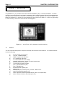
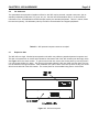
Congratulations on your purchase of the Horner Electric Workstation (WCI). The WCI (Workstation - Controller Interface) is a unique product in the industrial marketplace which combines standard personal computer hardware
with specialized communications interfaces. The WCI is panel mountable, gasketed, and is rated for NEMA 4 and
NEMA 12 applications. It operates from user supplied AC power, 80-267VAC, 50/60 Hz. It offers very high ratings
for noise immunity, and as such carries the CE mark designation.
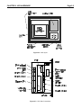
Figure 1-1. Horner Electric WCI (Workstation-Controller-Interface)
1.1
Features
The WCI offers standard personal computer functionality with enhanced communications. It’s hardware features
include the following:
a)
b)
c)
d)
e)
f)
g)
h)
i)
j)
k)
l)
m)
n)
o)
p)
Pentium-based microprocessor
8, 16, 32, or 64MB of DRAM
500MB or greater hard disk drive
3.5" 1.44MB floppy disk drive
10.4" Active Matrix TFT color display
Industrial pointing device (mouse) or optional touchscreen,
25-key tactile feel function keys
17-key tactile feel numeric keypad
Two (2) standard RS-232 ports,
Two (2) RS-485 ports
Enhanced Parallel (printer) port
keyboard port
Personal Computer Interface (PCIF) for Series 90TM-30 PLC
spare Full-length ISA expansion slot
optional GeniusTM PCIM-compatible interface (does not use spare slot)
optional Ethernet interface (eliminates spare slot)
CHAPTER 1: INTRODUCTION
1.2
Page 1-2
Key Components
The WCI product line is manufactured using high quality components from a variety of manufacturers. These
components are housed in a rugged, noise-immune package which has met the most stringent standards for
industrial equipment (CE mark). The two primary circuit board components are described below.
Intel Pentium-based motherboard
Through a close relationship with Intel, Horner Electric has integrated a standard, Intel manufactured motherboard
designed around the Pentium Processor. Beyond processing, this board includes interfaces to control the hard
drive, floppy drive, RS-232 ports, Parallel port, keyboard port and mouse port. By using a standard Intel
motherboard, Horner Electric can quickly keep pace with the latest microprocessor products as they are released
by Intel.
Sharp Active Matrix (TFT) Display
This brilliant display features a 10.4” diagonal width and a resolution of 640 x 480 pixels. It is backlit, and because
of its active matrix construction offers a wide viewing angle.
Horner Electric Communications board
In addition to high quality, standard hardware from Intel, the Horner Electric communications board provides
unique functionality to the WCI. The option board includes two RS-485 ports, which are well suited for serial
communications in an industrial environment. The board also provides an integrated Personal Computer Interface
(PCIF) port, which enables the WCI to directly control up to four racks of Series 90-30 I/O. A Genius PCIMcompatible option adds high speed communications and capability to control up to 31 devices on the Genius LAN.
An optional Ethernet card (residing in the spare ISA expansion slot) is also available. With these builit-in communications capabilities, the WCI can truly be effective as a Industrial Controller, or Human Machine Interface.
Operating System
The WCI is preloaded with MS-DOS on its units with 16MB or less of factory installed DRAM. The 32MB WCI
product is offered with Windows NT Workstation as its standard operating system. If MS-DOS is desired on this
model, it must be specifically requested.
Other operating systems (Windows ’95, Windows 3.11, etc.) may be requested, but typically require a minimum
order quantity.
Page 2-1
CHAPTER 2:
2.1
CHAPTER 2: WCI HARDWARE
WCI Hardware
Mounting Instructions
The WCI is panel mountable, typically mounted in an enclosure door. Mounting hardware includes ten (10) 6-32
studs. A rubber gasket provides the seal making the WCI oiltight and watertight when properly installed. The
installation procedure follows below:
1)
Cut and Drill the enclosure door as shown in WCI panel cutout diagram located in Appendix A at the rear
of this manual.
2)
Make sure that the external mouse or touchscreen cable is disconnected.
3)
From the front of the enclosure, place the WCI partway through the cutout
4)
Before tightening 6-32 hardware, remove the gasket’s adhesive backing paper.
5)
Carefully place the WCI all the way through the cutout, carefully sealing the gasket to the enclosure door.
6)
Tighten the 6-32 nuts to the mounting studs carefully, providing even pressure. Hardware should be
tightened until the unit is secure, and slight compression of the sealing gasket is evident. Do not overtighten!
7)
Re-install the external mouse or touchscreen cable as detailed later in this chapter.
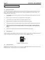
2.2
Providing Power
The WCI operates on user-supplied AC power, 80-267VAC, 50-60Hz. A three position removable terminal strip is
located on the upper left side of the unit, and its connection is shown in Figure 2-1 below:
Figure 2-1. Power Connections
2.3
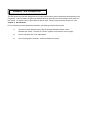
User Connections
Figure 2-2 shows the relative location of the WCI components. Figure 2-3 details the connections located on the
left side of the WCI. These figures are shown on the following page.
CHAPTER 2: WCI HARDWARE
Page 2-2
Figure 2-2. WCI layout
Figure 2-3. WCI User Connections
Page 2-3
2.4
CHAPTER 2: WCI HARDWARE
Pinouts
For standard RS-232, keyboard, mouse, and parallel port pinouts, consult the Intel portion of the documentation in
subsequent sections of this manual. This section covers the specific industrial communications interfaces provided by the Horner Electric communications board.
2.4.1
RS-485 Connections
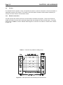
The WCI provides two RS-485 ports which are well suited to industrial environments. These are accessed as
COM3 and COM4, and have been specifically designed with the standard GE Fanuc RS-485 pinout. The pinout
follows below in Table 2-1, and the standard cable diagram for connection of the WCI to a Series 90 PLC follows
in Figure 2-4.
Table 2-1. RS-485 Ports (COM3 & COM4) pinouts
Figure 2-4. Cable pinout from WCI RS-485 port to Series 90 PLC.
CHAPTER 2: WCI HARDWARE
2.4.2
Page 2-4
PCIF Interface
The WCI’s PCIF connector allows the WCI to directly control Series 90-30 remote and/or expansion racks. As in
any PCIF application, the personal computer (in this case the WCI) takes the place of the PLC CPU, performing all
logic and I/O scanning. A variety of personal computer based industrial control software available in the marketplace supports the PCIF interface. A number of programming libraries (C++, DLL, etc.) are also available for those
using a standard development language such as Visual Basic or Visual C.
The WCI connects to GE Fanuc expansion and/or remote racks through standard GE Fanuc cables, or alternatively, through customer built-to-length cables. See the GE Fanuc document GFK-0356G, Series 90-30 Programmable Controller Installation Manual, for information on standard cables and custom cable specifications. This
manual also provides installation details crucial to a successful installation. For informational purposes, the pinout
for the 25-pin female PCIF connector follows in Table 2-2.
Table 2-2. PCIF Pinout
2.4.3
Genius Pinouts
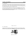
The Genius terminal strip and dipswitch are installed on each WCI whether or not the Genius option is actually
installed at the factory. A factory installed micro-GENI board, located within the WCI case, enables the Genius
PCIM functions. See the GE Fanuc document, GEK-90486F-1, Genius I/O System & Communications for details.
Figure 2-5. Genius pinouts
Page 2-5
2.4.4
CHAPTER 2: WCI HARDWARE
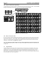
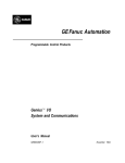
Genius Communications Dip Switches
The WCI features an 8-position dip switch for configuring the Genius baud rate and device number. This is accessible
through an access hole in the rear cover of the OIU, and its settings are listed as follows:
8
8
outputs
CLOSD
enabled
OPEN
disabled
7
6
5
4
3
2
1
Figure 2-6. Genius dispswitch settings
2.4.5
Mouse / Touchscreen Cable
Due to its construction utilizing a standard Intel motherboard, a physical cable connection must be made between
the mouse and mouse port. A short “jumper” cable is included with the WCI which has a PS/2 style connector on
either end. This cable must be connected by the user between the PS/2 mouse input port and the PS/2 mouse
output port. For port location, see Figure 2-3 on page 2-2.
In the case of touchscreen models, this cable connection must be made between the touchscreen output port and
either of the RS-232 ports (COM1 or COM2). The “jumper” cable supplied for these units has a 9-pin femal D-sub
on either end.
2.5
Keypad Interface
The WCI features 25 function keys and a full numeric keypad. The function keys can operate as “macro” keys,
allowing the press of one of these keys to generate one or more keystrokes, seen to the personals computer as
keyboard input. A driver disk is supplied which includes DOS, Windows NT, and Windows ‘95 drivers. As of
March 1996, only the DOS driver and utility was complete. As all the drivers become available, additional information will be added to this manual as Appendix C.
CHAPTER 2: WCI HARDWARE
2.6
Page 2-6
I/O Addresses
The specialized communications interfaces offered on the WCI require personal computer rescources, just as
standard peripherals (COM ports, LPT ports, etc.) do. See the Intel documentation later on in this manual for
information on the I/O addresses and IRQ interrupts used by the standard peripherals. Table 2-3, below, shows
the resources (namely, I/O addresses) used by the WCIs communications and keypad peripherals.
Table 2-3. WCI personal computer resources occupied
2.7
Expansion Slot
The WCI offers a single, full sized spare expansion slot which may utilize any standard personal computer card.
This slot is accessed from an access panel located on the bottom side of the WCI chassis (near the floppy drive).
See Figure 2-7 for the exact location. To gain access to that slot, remove the access panel by removing the ten
(10) 4-40 screws holding it in place. The removal of the plate makes the ISA slot visible, and the option card can
now be installed in the typical fashion. After installation, the option card’s connectors (if there are any) are accessible from the left side of the WCI chassis. The access plate can be reinstalled using the ten 4-40 screws.
Figure 2-7. WCI access panel
APPENDIX A: PANEL CUTOUT
APPENDIX B: INTEL DOCUMENTATION
The WCI product line has been designed around a high quality Pentium-based motherboard manufactured by Intel
Corporation. Intel Corporation has graciously allowed Horner to reprint the user documentation of their product in
this manual. For specific WCI functions added by Horner (PCIF, Genius, Keypad Interface, Mouse, etc.) see
Chapter 2: WCI Hardware.
Prior to examining the Intel supplied documentation, the following errata should be noted:
1)
The WCI has been designed using a Horner-designed Industrial Chassis, not the
standard Intel chassis. Therefore, the section “System Level Features” does not apply.
2)
The PCI expansion bus is not implemented.
3)
The on-board graphics controller, drivers and utilities are unused.