1
User’s manual
TransForm SCN
R5976968, Current Version
Title:
ID-no.:
Revision:
Date:
chapter 1
chapter 2
chapter 3
chapter 4
chapter 5
chapter 6
chapter 7
chapter 8
new:
corr.:
add.:
TRANSFORM SCN – User’s Manual
R5976968
02
June-2006
Main issue
update
corr.
rev. 02: changed according to firmware 2.0.1.12 (remote pointer handling)
The corresponding chapters are new or completely revised.
Passages of the corresponding chapter were corrected; see modification bars.
Passages of the corresponding chapter were added; see modification bars.
This manual refers to following hardware and software configurations of TRANSFORM SCN:
Firmware version
2.0.1.12
Document History
Modifications which result in a new version are indicated by a vertical bar.
Barco – TransForm SCN – R5976968 – Revision 02 – June 2006
___________________________________________________________________________________________________
ii
Trademarks
Brand and product names mentioned in this manual may be trademarks, registered trademarks or copyrights of
their respective holders. All brand and product names mentioned in this manual serve as comments or examples
and are not to be understood as advertising for the products or their manufacturers.
Copyright © 2006 by Barco
Die Weitergabe sowie die Vervielfältigung aller Unterlagen, die von uns überlassen werden, deren Verwertung
und Mitteilung ihres Inhaltes an Dritte ist nicht gestattet, soweit dies nicht ausdrücklich zugestanden ist.
Urheberrechte, insbesondere auch solche an Software, werden nur insoweit übertragen, als es für die Erreichung
des speziellen Vertragszwecks erforderlich ist. Zuwiderhandlungen können zu Schadensersatz verpflichten. Alle
Rechte aus der Erteilung eines Patents oder der Eintragung eines Gebrauchsmusters verbleiben bei uns.
Copyright © 2006 by Barco
All rights reserved. No part of this document may be copied, reproduced or translated. It shall not otherwise be
recorded, transmitted or stored in a retrieval system without the prior written consent of Barco.
Guarantee and Compensation
Barco provides a guarantee relating to perfect manufacturing as part of the legally stipulated terms of guarantee.
On receipt, the purchaser must immediately inspect all delivered goods for damage incurred during transport, as
well as for material and manufacturing faults. Barco must be informed immediately in writing of any complaints.
The period of guarantee begins on the date of transfer of risks, in the case of special systems and software on
the date of commissioning, at the latest 30 days after the transfer of risks. In the event of justified notice of
complaint, Barco can repair the fault or provide a replacement at its own discretion within an appropriate period.
If this measure proves to be impossible or unsuccessful, the purchaser can demand a reduction in the purchase
price or cancellation of the contract (redhibition). All other claims, in particular those relating to compensation for
direct or indirect damage, and also damage attributed to the operation of software as well as to other services
provided by Barco, being a component of the system or independent services, will be deemed invalid provided
the damage is not proven to be attributed to the absence of properties guaranteed in writing or due to the intent
or gross negligence on the part of Barco.
If the purchaser or a third party carries out modifications or repairs on good delivered by Barco, or if the goods
are handled incorrectly, in particular if the systems are commissioned or operated incorrectly or if, after the
transfer of risks, the goods are subject to influences not agreed upon in the contract, all guarantee claims of the
purchaser will be rendered invalid. Not included in the guarantee coverage are system failures which are attributed to programs or special electronic circuitry provided by the purchaser, e. g. interfaces. Normal wear as well
as normal maintenance are not subject to the guarantee provided by Barco either.
The environmental conditions as well as the servicing and maintenance regulations specified in this manual must
be complied with by the customer.
Barco – TransForm SCN – R5976968 – Revision 02 – June 2006
__________________________________________________________________________________________________
iii
Revision sheet
To:
•
Barco Control Rooms GmbH
An der Rossweid 5, D-76229 Karlsruhe
Phone: +49-721-6201-0, Fax: +49-721-6201-298
E-mail: [email protected], Web: www.barcocontrolrooms.com
From:
Date:
Please correct the following points in this documentation (R5976968):
page
wrong
Barco – TransForm SCN – R5976968 – Revision 02 – June 2006
correct
__________________________________________________________________________________________________
iv
Contents
1 Introduction......................................................................................................................................... 1-1
1.1 How this manual is organized .....................................................................................................................1-2
1.2 Styles and symbols.......................................................................................................................................1-3
1.3 Safety instructions ........................................................................................................................................1-4
1.3.1 Standards .............................................................................................................................................1-4
1.3.2 Precautions ..........................................................................................................................................1-4
1.3.3 Unpacking of devices...........................................................................................................................1-5
1.3.4 Installation ...........................................................................................................................................1-6
1.3.5 Servicing...............................................................................................................................................1-6
1.3.6 Cleaning ...............................................................................................................................................1-6
1.3.7 Re-packing ...........................................................................................................................................1-6
1.4 Online manual ..............................................................................................................................................1-7
2 Summary ............................................................................................................................................. 2-1
2.1 Properties......................................................................................................................................................2-2
3 Getting started .................................................................................................................................... 3-1
3.1 Examining .....................................................................................................................................................3-2
3.1.1 TransForm SCN .....................................................................................................................................3-2
3.2 Cabling ..........................................................................................................................................................3-4
3.2.1 Power supply .......................................................................................................................................3-4
3.2.2 Graphical data......................................................................................................................................3-5
3.2.3 Network ...............................................................................................................................................3-5
3.2.4 Remote Pointer....................................................................................................................................3-6
3.3 Starting up ....................................................................................................................................................3-7
3.3.1 Connecting ...........................................................................................................................................3-7
3.3.2 Switching on ........................................................................................................................................3-7
3.3.3 Switching off ........................................................................................................................................3-7
4 Operating ............................................................................................................................................ 4-1
4.1 Encoder .........................................................................................................................................................4-2
4.1.1 Encoding...............................................................................................................................................4-2
4.1.2 DDC .......................................................................................................................................................4-2
4.1.3 Loop through........................................................................................................................................4-2
4.2 Remote pointer ............................................................................................................................................4-3
4.2.1 Configuration........................................................................................................................................4-4
4.2.2 Using remote pointer ..........................................................................................................................4-5
4.3 TransForm SCN web interface......................................................................................................................4-6
4.3.1 Starting the TransForm SCN web interface.........................................................................................4-6
4.3.2 Structure of the TransForm SCN web interface ..................................................................................4-6
4.3.3 General settings...................................................................................................................................4-7
4.3.4 Network settings .................................................................................................................................4-8
4.3.5 Encoder settings – Destination ..........................................................................................................4-10
Barco – TransForm SCN – R5976968 – Revision 02 – June 2006
___________________________________________________________________________________________________
v
4.3.6 Encoder settings – properties ............................................................................................................4-11
4.3.7 Encoder settings – timing ..................................................................................................................4-13
4.3.8 Encoder settings – status ...................................................................................................................4-15
4.3.9 Keyboard & mouse – Remote pointer...............................................................................................4-16
4.3.10 Keyboard & mouse – Settings .........................................................................................................4-21
4.3.11 Status summary...............................................................................................................................4-22
4.3.12 System Access – Reboot ..................................................................................................................4-23
4.3.13 System access – Devices .................................................................................................................4-24
4.3.14 Firmware upgrade ...........................................................................................................................4-25
4.3.15 Administration login/logout ...........................................................................................................4-26
4.3.16 Change admin password.................................................................................................................4-27
5 Maintenance ....................................................................................................................................... 5-1
5.1 Cleaning ........................................................................................................................................................5-1
6 Advanced configuration...................................................................................................................... 6-1
6.1 Initial configuration of the network settings ..............................................................................................6-2
6.2 Resetting factory settings ............................................................................................................................6-3
7 Technical appendix ............................................................................................................................. 7-1
7.1 Technical data...............................................................................................................................................7-2
7.2 Interfaces ......................................................................................................................................................7-4
7.3 Order codes...................................................................................................................................................7-6
8 Trouble shooting ................................................................................................................................. 8-1
8.1 Errors .............................................................................................................................................................8-2
8.1.1 General errors ......................................................................................................................................8-2
8.2 Contact ..........................................................................................................................................................8-3
Barco – TransForm SCN – R5976968 – Revision 02 – June 2006
__________________________________________________________________________________________________
vi
1. Introduction
1 Introduction
This chapter explains the structure of the manual itself and the used typographic styles and symbols. Safety information is provided concerning the operation of computer systems from Barco.
Barco – TransForm SCN – R5976968 – Revision 02 – June 2006
________________________________________________________________________________________________
1-1
1. Introduction
1.1 How this manual is organized
This manual describes design and startup of TRANSFORM SCN from Barco. It is divided into eight chapters:
•
Introduction
explains the structure of the manual itself and the used typographic styles and symbols. Safety information is
provided concerning the operation of computer systems from Barco.
•
Summary
gives an overview about the features of TRANSFORM SCN.
•
Getting Started
describes the set up of TRANSFORM SCN.
•
Operating
shows the capabilities which TRANSFORM SCN offers in decoding RGB data.
•
Maintenance
describes the maintenance of TRANSFORM SCN.
•
Advanced Configuration
may provide useful information for reconfiguring the software of your TRANSFORM SCN.
•
Technical Appendix
gives tabular overviews about the technical details of TRANSFORM SCN, its components and of their interfaces.
•
Troubleshooting
gives advice, if your TRANSFORM SCN does not operate properly.
Chapters, pages, figures and tables are numbered separately. Chapters are indicated by a »point syntax«, e. g.
4.2.3, pages by a »dash syntax«, e. g. 2-1, as figures and tables are, e. g. figure 5-4.
Barco – TransForm SCN – R5976968 – Revision 02 – June 2006
________________________________________________________________________________________________
1-2
1. Introduction
1.2 Styles and symbols
The typographic styles and the symbols used in this document have the following meaning:
Bold
Labels, menus and buttons are printed in the Bold font.
Condensed
Links to both other chapters of this manual and to sites in the Internet are printed
condensed. In the on-line version of this manual all hyperlinks appear teal.
Courier
Names of files and parts from programs are printed in the Courier font.
Courier bold
Inputs you are supposed to do from the keyboard are printed in Courier bold font.
ª
Within a piece of programming code this arrow marks a line, that must be made up in two
lines, though meant to be one line.
If you do not heed instructions indicated by this symbol there is a risk of damage to the
equipment!
If you do not heed instructions indicated by this symbol there is a risk of electrical shock and
danger to personal health!
If you do not heed instructions indicated by this symbol there is a risk of damage to parts,
which are sensitive to electrostatic charge!
If you do not heed instructions indicated by this symbol there is a risk to get harmed by sharp
objects!
If you do not heed instructions indicated by this symbol there is a risk that parts may
explode!
If you do not heed instructions indicated by this symbol there is a risk that hot parts impact
persons or objects!
The sheet icon indicates additional notes.
Next to this icon you find further information.
This arrow marks tips.
Next to this icon you find important notes.
Barco – TransForm SCN – R5976968 – Revision 02 – June 2006
________________________________________________________________________________________________
1-3
1. Introduction
1.3 Safety instructions
This section describes safety precautions which must be observed when installing and operating a product from
Barco.
1.3.1 Standards
Safety regulations
TRANSFORM SCN is built in accordance with the requirements of the international safety standard IEC-60950-1,
UL 60950-1 and CSA C22.2 No. 60950-1-03, which are the safety standards of information technology equipment
including electrical business equipment.
These safety standards impose important requirements on the use of safety critical components, materials and
isolation, in order to protect the user or operator against the risk of electric shock and energy hazard, and having
access to live parts.
Safety standards also impose requirements to the internal and external temperature variations, radiation levels,
mechanical stability and strength, enclosure construction and protection against risk of fire.
Simulated single fault condition testing ensures the safety of the equipment to the user even when the equipment's normal operation fails.
Electromagnetic interference
Electromagnetic emission of TRANSFORM SCN complies with EN55022 class A, EN61000-3-2, EN61000-3-3 and the
limits for a class A digital device, pursuant to Part 15 of the FCC Rules.
Electromagnetic immunity of TRANSFORM SCN complies with EN55024.
1.3.2 Precautions
For your own protection, observe the following safety precautions when installing,
operating and servicing your device:
•
Before operating the units please read this manual thoroughly and retain it for future reference!
•
Observe all warnings and instructions printed on the devices!
•
Servicing not explicitly mentioned in this manual should never be carried out by unauthorized personnel!
Never open the case of the unit!
•
To prevent fire or electrical shock hazard, do not expose this unit to rain or moisture!
•
This product should be operated from an AC power source!
•
Check that the voltage and frequency of your power supply match those printed on the device label with the
rated electrical values!
•
If you are not sure of the type of AC power available, consult your dealer or local power company!
•
This product is equipped with a desktop power adapter with a 3-pin power inlet, a plug having a third
(grounding) pin. This plug will only fit into a grounding-type power outlet. This is a safety feature. If you are
unable to insert the plug into the outlet, contact your electrician to replace your obsolete outlet. Do not defeat the purpose of the grounding–type plug!
•
This desktop power adapter must be grounded (earthed) via the supplied 3 conductor AC power cable. (If the
supplied cable is not the correct one, consult your dealer.)
Barco – TransForm SCN – R5976968 – Revision 02 – June 2006
________________________________________________________________________________________________
1-4
1. Introduction
Mains lead (AC power cord) with CEE 7 plug:
The wires of the mains lead are colored in accordance with the following code:
yellow + green
blue
brown
Earth (Ground)
Neutral
Line (Live)
Figure 1-1
CEE 7 plug
Power cord with NEMA 5-15 plug:
•
The cord set must be UL-approved and CSA-certified.
•
The minimum specification for the flexible cord is No. 18 AWG, Type SVT or SJT, 3-conductor.
•
The cord set must have a rated current capacity of at least 10A.
•
The attachment plug must be an Earth-grounding type with a NEMA 5-15P (10A, 125V) configuration.
The wires of the power cord are colored in accordance with the following code.
green or yellow + green
blue or white
brown or black
Earth (Ground)
Neutral
Line ( Live)
Figure 1-2
NEMA 5-15 plug
•
Do not allow anything to rest on the desktop power adapter and on the power cord. Do not locate this product where people will walk on the cord. To disconnect the cord, pull it out by the plug. Never pull the cord itself.
•
If an extension cord is used with this product, make sure that the total of the ampere ratings on the products
plugged into the extension cord does not exceed the extension cord ampere rating.
•
Never push objects of any kind into this product through cabinet slots as they may touch dangerous voltage
points or short out parts that could result in a risk of fire or electrical shock.
•
Never spill liquid of any kind on the product. Should any liquid or solid object fall into the cabinet, unplug the
set and have it checked by qualified service personnel before resuming operations.
•
Lightning - For extra protection for this video product during a lightning storm or when it is lift unattended
and unused for a long period of time, unplug it from the wall outlet. This will prevent damage to the unit
due to lightning and AC power-line surges.
1.3.3 Unpacking of devices
Note advises on the packaging for unpacking!
Barco – TransForm SCN – R5976968 – Revision 02 – June 2006
________________________________________________________________________________________________
1-5
1. Introduction
1.3.4 Installation
•
Do not place this unit on an unstable cart, stand, or table. The unit may fall, causing serious damage to it.
•
Do not use this unit near water.
•
Use only the power cord and the desktop power adapter supplied with your unit. While appearing to be
similar, other desktop power adapters and power cords have not been safety tested at the factory and may
not be used to power the unit. For a replacement power cord, contact your dealer.
•
Slots and openings in the cabinet and the sides are provided for ventilation; to ensure reliable operation of
the unit and to protect it from overheating, these openings must not be blocked or covered. The openings
should never be blocked by placing the product on a bed, sofa, rug, or other similar surface. This product
should never be placed near or over a radiator or heat register. This unit should not be placed in a built-in installation or enclosure unless proper ventilation is provided.
•
The maximum recommended ambient temperature for this equipment is 40° C.
•
When using the unit in a multi-unit rack assembly or closed assembly the ambient temperature inside the
assembly may not succeed the maximum rated ambient temperature.
•
When installed in a rack, the installation should be such that the amount of air flow required for safe operation of the equipment is not compromised. The mounting of the equipment should be such that no hazardous
condition is achieved due to uneven mechanical loading.
1.3.5 Servicing
Mechanical or electrical modifications others than described in this manual must not be made to the devices.
Barco is not liable for damages resulting from modified devices.
Only authorized personnel should carry out other maintenance work not explicitly
mentioned in this manual!
Never open the case of the TRANSFORM SCN without first disconnecting the desktop power
adapter! Measurements and tests with the opened device may be carried out only in the
factory or by specially trained personnel, due to the dangers of electrical shock.
1.3.6 Cleaning
Unplug this product from the wall outlet before cleaning. Do not use liquid cleaners or aerosol cleaners. See section 5.1 Cleaning for a cleaning instruction!
1.3.7 Re-packing
Keep the original shipping carton and packing material; they will come in handy if you ever have to ship your
unit. For maximum protection, repack your set as it was originally packed at the factory.
Barco – TransForm SCN – R5976968 – Revision 02 – June 2006
________________________________________________________________________________________________
1-6
1. Introduction
1.4 Online manual
On the TRANSFORM SCN CD R5976969 this manual R5976968 can also be found in electronic form. Insert the CD in
the CD ROM drive of your PC. If autorun is enabled on TRANSFORM SCN the start page of the CD comes up. If the CD
does not start automatically, open the file index.htm from the CD in a browser. There you will find the documentation.
Acrobat Reader can be used to view R5976968_XX_owners.pdf. Adobe® Acrobat® Reader is free and freely
distributable software that lets you view and print Adobe Portable Document Format (PDF) files.
If Acrobat Reader is already installed, the manual can be viewed just by a click on the link. Else the Acrobat
Reader must be installed first. Its setup program can be found on the CD in section 3rd party tools.
Barco – TransForm SCN – R5976968 – Revision 02 – June 2006
________________________________________________________________________________________________
1-7
2. Summary
2 Summary
This chapter gives an overview about the features of TRANSFORM SCN.
Barco – TransForm SCN – R5976968 – Revision 02 – June 2006
________________________________________________________________________________________________
2-1
2. Summary
2.1 Properties
The TRANSFORM SCN, a member of Barco's family of networked visualization products, provides lossless compression and transport of computer graphics over standard networks. It is especially suited for distributed visualization of secure and/or legacy applications over IP networks.
With TRANSFORM SCN, any computer graphics source can be captured and transported over an IP network without
the need for extra software on the source computer (host PC). This allows better security and requires less processing power than software screen scraping tools.
TRANSFORM SCN provides amongst others the following features:
•
external capture of the computer graphics output allowing complete host computing platform independency
•
graphic sources up to UXGA@60 Hz
•
active loop through with sync recovery for graphics data
•
DDC loop through
•
DDC generation, if graphics loop through is not used
•
hardware based encoding with optimal compression performance
•
distribution of graphics stream via unicast and multicast UDP
•
USB keyboard and mouse emulation
•
browser based configuration
Basic setup
A setup where the graphics output of the host PC is just captured and displayed is shown below. The graphical
output of the host PC is connected to TRANSFORM SCN and looped through to the host PC’s monitor. By this an
operator will not be interfered and no software needs to be installed on the host PC.
TRANSFORM SCN converts and compresses the graphical signal to a stream of graphical data and distributes it via
the LAN. This stream can be decoded by a wall controller of Barco which is equipped with a STREAMING VIDEO CARD
and be displayed on a display wall or other projection device.
TRANSFORM SCN is controlled by a master PC via TCP/IP. Any PC in the same LAN can be used for this purpose.
Display wall
TransForm SCN
Encoder
DVI
Host PC
Image generator
Master PC
DVI
Wall controller
with Streaming Video Card decoder
LAN TCP/IP
Figure 2-1
basic setup configuration
Barco – TransForm SCN – R5976968 – Revision 02 – June 2006
________________________________________________________________________________________________
2-2
2. Summary
Setup with remote pointer
In a setup with remote pointer in addition the mouse and keyboard of another computer can be used to operate
the screen of the host PC. This can either be the mouse and keyboard of the master PC or, in combination with
Barco’s wall management software APOLLO, the wall controller or another APOLLO client.
For remote pointer just an additional USB connection between host PC and TRANSFORM SCN is required.
Display wall
TransForm SCN
Encoder
DVI
Host PC
Image generator
Master PC
Remote pointer
DVI
USB for remote pointer
Wall controller
with Streaming Video Card decoder
LAN TCP/IP
Figure 2-2
setup with remote pointer
Barco – TransForm SCN – R5976968 – Revision 02 – June 2006
________________________________________________________________________________________________
2-3
3. Getting started
3 Getting started
This chapter describes the set up of the TRANSFORM SCN.
Barco – TransForm SCN – R5976968 – Revision 02 – June 2006
________________________________________________________________________________________________
3-1
3. Getting started
3.1 Examining
3.1.1 TransForm SCN
The front:
12
1 2 3 4
9
10
1
red LED 1:
2
green LED 2:
3
green LED 3:
4
green LED 4:
5
red LED 5:
6
green LED 6:
7
green LED 7:
8
green LED 8:
9
DVI in
DVI out
USB (for keyboard and mouse connection)
ventilation slots
10
11
12
12
5 6 7 8
temperature
on – temperature error
DDC Hot Plug detect
on – display is connected and generates hot plug signal
off – display is not connected or display does not support hot plug signal
signal detection
on – analog or digital Sync detected
off – no Sync detected
Ethernet activity
blinking – Ethernet activity
Fan
on – fan error
on, LED 1 and LED 5 blinking – internal error
software heartbeat
blinking – OK, otherwise there is an internal firmware error
input type
on – analog input
off – digital input
power
on – power OK
Figure 3-1
front view of TransForm SCN
On the front panel of TransForm SCN there are eight LEDs [1-8], indicating the operating state of the device. On
the left side there is a DVI in connector [9] and a DVI out connector [10] to insert and loop through the source
signal. On the right side there is a USB connector [11] for remote operation of the screen content.
Barco – TransForm SCN – R5976968 – Revision 02 – June 2006
________________________________________________________________________________________________
3-2
3. Getting started
The back
13
13
14
15
16
17
18
13
15 14 16
13
17
18
ventilation slots
LAN adapter (10/100 Mbps) with the following LED signals:
yellow LED 1 Ethernet link
on – 100 Base-TX connection
off – 10 Base-TX connection
green LED 2 Ethernet activity
on – valid link
blinking – traffic
off – no valid link
LED: power OK
power connection
Figure3-2
rear view of TRANSFORM SCN
In the middle of the rear there is the network adapter [14] to connect to the LAN. On the right hand side there
are the power connection [18] and a LED [17] indicating power OK.
To disconnect TransForm SCN from the power supply the DC output connector of the desktop
power adapter has to be pulled of the power connection [18]. Therefore the back panel has
to be easily accessible!
Barco – TransForm SCN – R5976968 – Revision 02 – June 2006
________________________________________________________________________________________________
3-3
3. Getting started
3.2 Cabling
3.2.1 Power supply
TRANSFORM SCN is supplied with a desktop power adapter.
Check the power rating on your outlet before connecting the desktop power adapter of
TRANSFORM SCN to the wall outlet or to a power strip. Contact your facilities manager or a
qualified electrician if you are not sure what type of power is supplied to your building.
The desktop power adapter of TRANSFORM SCN is designed to operate with single-phase
power systems having a grounded neutral conductor. To reduce the risk of electrical shock,
do not plug into any other type of power system.
•
Plug the female end of the power cord into the desktop power adapter.
Figure 3-3
Mains connection
•
Plug the male end of the power cord into a power outlet.
•
Plug the plug of the DC output into the power connection [18] of the TRANSFORM SCN.
Barco – TransForm SCN – R5976968 – Revision 02 – June 2006
________________________________________________________________________________________________
3-4
3. Getting started
3.2.2 Graphical data
The TRANSFORM SCN is capable to decode the analog or digital graphical output of a computer.
Formats
An analog or digital VESA source up to 1600×1200@60 Hz (UXGA) with up to 24 bpp color depth can be encoded,
please refer also to section 7.1 Technical data.
Connection
The TRANSFORM SCN comes with a set of cables and adapters for graphical data:
•
cable DVI-I –> DVI-I
•
cable VGA 15 pin -> DVI-A
•
adapter DVI-A -> VGA 15 pin
They can be used depending on the type of the graphic connectors of the graphic card of the host PC and of the
monitor.
For the connection of the host PC with the DVI in [9] connector of the TRANSFORM SCN the provided cables DVI-I –
DVI-I or VGA – DVI-A can be used, depending on the connector type of the host PC.
If you want to loop through the signal and display it on a monitor or other displaying device, connect the DVI out
[10] connector with the displaying device. For that purpose you can use the so far used cable. If this cable has a
VGA plug you can use the DVI-A -> VGA 15 pin adapter to connect it to the TRANSFORM SCN.
9
10
Figure 3-4
connecting a graphical data source
To be able to use DDC information of the monitor, it must be connected before the
TransForm SCN is connected to the power supply.
3.2.3 Network
For the network connection the network adapter on the back of the TRANSFORM SCN is used. It consists of an RJ45
connector suitable for a 10/100 Mbps connection.
Connection
Plug the network cable into the LAN adapter [14] on the rear of TRANSFORM SCN.
Network requirements
property
requirement
speed
100 Mbps full duplex
port
switched (no hub)
bandwidth
capacity to transport a 30 Mbps TRANSFORM SCN stream without packet loss
Table 3-1
Barco – TransForm SCN – R5976968 – Revision 02 – June 2006
________________________________________________________________________________________________
3-5
3. Getting started
3.2.4 Remote Pointer
To operate the screen of the host PC its local mouse and keyboard can be used. Furthermore to remotely control
the screen also the mouse and keyboard of the master PC can be used. Mouse and keyboard signals are transferred over the LAN to the TRANSFORM SCN. The TRANSFORM SCN transforms the signal to a USB signal and sends it
over a USB connection to the host computer. For the USB connection a suitable USB cable is included in delivery.
Connection
Plug the USB connector type B (more quadratic shape) of the cable into the USB jack [11] of the TRANSFORM SCN.
Plug the other side of the USB cable (connector type A, flat rectangular shape) into an USB jack of the host PC.
Figure 3-5
connection of remote pointer – USB cable
The master PC and the TRANSFORM SCN have to be connected to the same LAN.
Please refer also to section 4.2 Remote pointer for the usage of remote pointer.
Barco – TransForm SCN – R5976968 – Revision 02 – June 2006
________________________________________________________________________________________________
3-6
3. Getting started
3.3 Starting up
3.3.1 Connecting
•
Connect TRANSFORM SCN to the local area network by connecting the network adapter! Please, refer to section
3.2.3 Network!
•
If desired, connect a monitor to the DVI out connector of the TRANSFORM SCN, please refer to section 3.2.2
Graphical data.
•
Connect the TRANSFORM SCN to the power net; please, refer to section 3.2.1 Power supply!
•
Connect the graphic source to TRANSFORM SCN; please refer to section 3.2.2 Graphical data.
•
If you want to remotely control the host PC, connect the TRANSFORM SCN and the computer who generates the
graphical source with the provided USB cable; please refer to sections 3.2.4 Remote Pointer!
3.3.2 Switching on
Initial system start after delivery
The TRANSFORM SCN is preconfigured at the factory with a default IP address. Therefore before connecting the TRANSFORM SCN to your company’s network, its network settings have to be adapted.
For the configuration of the network properties please refer to 6.1 Initial configuration of the network
settings.
When power is applied to the TRANSFORM SCN the green LED power OK [17] on its back is lighting and the device
is automatically switched on and initializes. When initialization is ready, the green LED software heartbeat [6]
starts blinking and the device is in operation mode.
The device is controlled via the TRANSFORM SCN web interface; please refer to section 4.3 TransForm SCN web
interface.
If the host PC does not support DDC, then the output timing of the host PC has to be checked. It may not exceed
a resolution of UXGA (1600×1200), which is the maximal TRANSFORM SCN input resolution. Please refer also to
section 4.1.2 DDC and 7.1 Technical data.
3.3.3 Switching off
To switch off the TRANSFORM SCN simply the power supply has to be disconnected.
If TransForm SCN is switched off the graphical signal is also no longer looped through.
Therefore after switching off the TransForm SCN you should connect the monitor directly to
the host PC, to be able to see the graphical output!
Barco – TransForm SCN – R5976968 – Revision 02 – June 2006
________________________________________________________________________________________________
3-7
4. Operating
4 Operating
This chapter shows the capabilities that TRANSFORM SCN offers for decoding graphical data and for using remote
control. It explains also how the TRANSFORM SCN is configured.
Barco – TransForm SCN – R5976968 – Revision 02 – June 2006
________________________________________________________________________________________________
4-1
4. Operating
4.1 Encoder
4.1.1 Encoding
A digital or analog graphical source up to UXGA@60 Hz is connected to the graphical input of the encoder.
The encoder detects the source and, if recognized, automatically adjusts the necessary parameters. In this way
no manual adaptation is necessary when the source changes.
4.1.2 DDC
The Display Data Channel or DDC is a digital connection between a computer display and a graphics adapter that
allows the display to communicate its specifications to the adapter.
The TRANSFORM SCN provides DDC data at the input connector for the host PC which creates the image. This DDC
data is in general looped through from the monitor. If a monitor gets connected to the TRANSFORM SCN while the
TRANSFORM SCN is already in operation, the host PC will not adapt its output timing for this monitor. For this case
or for monitors without DDC capability an upper limit for the timing can be set and can be sent from the
TRANSFORM SCN instead of looped through DDC data to the host PC. The upper limit can also be used to optimize
bandwidth usage.
The table below shows which setting is used in which situation:
incoming DDC at output connector
DDC at input connector
incoming monitor DDC ≤ upper limit DDC
monitor DDC
incoming monitor DDC > upper limit DDC
upper limit DDC
monitor without DDC
upper limit DDC
no monitor connected
upper limit DDC
Figure 4-1
DDC – operating mode
Anyhow for decoding the detected timing the parameters of the source are used, not the DDC information, ensuring that also graphical sources of systems which are not DDC compliant are optimally decoded.
The maximum DDC timing is set by means of the TRANSFORM SCN web interface, please refer to section 4.3.7
Encoder settings – timing.
4.1.3 Loop through
The graphical output port is an active loop through of the graphical input with sync recovery. The table below
shows which output signal is provided on basis of the provided input:
input signal
output signal
analog
analog and digital simultaneously
digital
digital
Figure 4-2
loop through – format of input and output signal
Barco – TransForm SCN – R5976968 – Revision 02 – June 2006
________________________________________________________________________________________________
4-2
4. Operating
4.2 Remote pointer
The graphics output of the host PC can not only be compressed and streamed, it is also possible to use the remote pointer functionality of TRANSFORM SCN to remotely interact with the content of the screen.
Mode of operation
The remote pointer functionality offers a method to interact with the host PC without using its own mouse and
keyboard. There are two manners to do so:
•
Usage of a PC which is a client computer for Barco’s wall management software APOLLO (FRG viewer from
APOLLO version 1.8 SR1 on)
•
Usage of mouse and keyboard of a PC via the TRANSFORM SCN web interface (master PC)
This manual describes only the latter. For an instruction of remote pointer with APOLLO please refer to the APOLLO
user’s manual.
The mouse and keyboard signal of the master PC is transferred over the LAN to the TRANSFORM SCN. The
TRANSFORM SCN transforms the received signal to a USB coded signal and sends it over a USB cable to the host PC,
which reacts to the signal like to its own keyboard and mouse.
Wall controller
with Streaming Video Card decoder
TCP/IP LAN
Master PC
Remote pointer
Host PC
Image generator
TransForm SCN
Encoder
DVI
USB for remote control
Figure 4-3
Configuration for remote pointer
Barco – TransForm SCN – R5976968 – Revision 02 – June 2006
________________________________________________________________________________________________
4-3
4. Operating
4.2.1 Configuration
System requirements
•
host PC has a USB connector available
•
operating system of the host PC supports the USB HID profile
•
operating system of the master PC: Windows 2000 or Windows XP
•
Java runtime environment is installed on the master PC
Connecting the USB cable and device installation on the host PC
Connect the USB cable as explained in section 3.2.4 Remote Pointer.
The new device has to be installed on the host PC. The manner to do so depends on the operating system of the
host PC. On a Windows 2000 or Windows XP system, for example, the Found new hardware wizard will come up
automatically and guide through the installation.
A total of three devices have to be installed. This is at first the new TRANSFORM SCN USB device, a low-speed USB
composite device. This device includes two further USB interfaces, the remote HID-keyboard (a standard 104-key
keyboard) and the remote HID-mouse (a standard 3-button wheel mouse). They work according to the USB HID
Boot Protocol. Operating systems from 1998 on have a built-in support for HID Boot devices. These two HID interfaces have to be installed as well.
Java runtime environment on the master PC
On the master PC the Sun Java Virtual Machine must be installed to provide the appropriate Java runtime environment for operation of the remote pointer. The installation file is located on the CD R5976969 Manuals &
Supplement. Insert the CD into the master PC and make a local copy of the file from the CD-ROM \3rd
party\sun\j2re-1_4_2_05-windows-i586-p.exe. Start the installation by a double click on the local
copy of the file. After a short preparation phase the InstallShield Wizard comes up. First you will have to accept
the license agreement and then select the setup type. The Typical setup is sufficient for this purpose. After that
the installation starts and takes some minutes. As soon as clicking on the final Finish button, the Java Virtual
Machine is available on the master PC.
To install the Java runtime environment you must be logged in on the master PC with administrative rights.
For proper operation the browser settings have to allow the usage of Java script.
Make sure that Java Script is enabled for the browser you use:
•
In the Java Plug-in Control Panel (Start -> Settings -> Control Panel -> Java Plug-in) select the browser you
are using.
In the browser enable the usage of Java applets, e.g. for Internet Explorer 4.x or higher this is the following:
•
Click Tools -> Internet Options…
•
On the Advanced tab go to Java (Sun) and enable Use Java …
•
On the tab Security click the Custom Level … button and enable Scripting of Java applets
•
Click OK to save the settings
Barco – TransForm SCN – R5976968 – Revision 02 – June 2006
________________________________________________________________________________________________
4-4
4. Operating
Adapting the keyboard of the master PC
If using the keyboard of the master PC for remote control, the type of the keyboard and the used keyboard layout have to be considered. Depending on the keyboard and keyboard scheme that is used on the master PC, all
or part of the following actions have to be done:
•
Keyboard which has a left Shift key that is smaller than the Caps Lock key
There is one more key compared to the keys on a US keyboard. To be able to use this extra key through remote pointer, please follow the whole procedure explained below (steps 1 to 4).
•
Keyboard which has a left Shift key that is larger than the Caps Lock key (a standard US QWERTY
keyboard)
Make sure, that a keyboard layout without dead keys is used. This means check with step 3 that US and not
US-international is selected. Check also step 4.
Adaptation steps for the keyboard:
1. Installation of US Barco layout
On the master PC execute the file BarcoLayout.exe. You find it on the TRANSFORM SCN CD R5976969. This
installs the suitable keyboard layout, called US (BARCO). It is installed without further notice.
If the TRANSFORM SCN web interface is open while the keyboard layout gets installed, it has to
be closed and restarted to make the changed keyboard layout available for the usage with
remote pointer!
2. Adding US Barco layout to the Regional Options
On the master PC open the Regional Options dialog (Start -> Settings -> Control Panel -> Regional Options).
Go to the Input Locales tab and click Change.
In the Text Services dialog click Add…
In the Add Input Language dialog select from the Input Language list the entry US (Barco).
3. Selecting keyboard layout from the Language Bar
In the Notification area of the master PC there is usually the icon of the Language Bar. It shows within a
blue square a shortcut for the used keyboard layout. Make sure that the new entry is selected.
4. Adapting the keyboard settings of the host PC
On the host PC adapt the keyboard layout to the keyboard layout that the master PC uses.
4.2.2 Using remote pointer
The remote pointer is completely operated via the TRANSFORM SCN web interface, please refer to section 4.3.9
Keyboard & mouse – Remote pointer to use the remote pointer and to section 4.3.10 Keyboard & mouse – Settings for
configuration and activation of the remote pointer.
Multiple master PCs may use the TransForm SCN web interface simultaneously and by this
the remote pointer. There may arise conflicts between the input of distinct master PCs, e.g.
keyboard entries might be combined which might lead to send unintended shortcut keys.
Barco – TransForm SCN – R5976968 – Revision 02 – June 2006
________________________________________________________________________________________________
4-5
4. Operating
4.3 TransForm SCN web interface
The TRANSFORM SCN offers via the LAN a web based graphical user interface. It provides access to configuration
parameters and operation of TRANSFORM SCN. The software can be accessed from any PC within the same network
allowing maximal flexibility in control.
4.3.1 Starting the TransForm SCN web interface
The graphical user interface of the configuration software of TRANSFORM SCN is automatically started, when calling
its IP address via http. Therefore please follow the steps below:
•
On a computer which is connected to the same network as the TRANSFORM SCN open a web-browser.
•
Make sure, that the usage of cookies is enabled for the web content zone of the TRANSFORM SCN.
•
Into the address bar of the browser enter the IP address of the TRANSFORM SCN, e.g.:
http://192.168.180.14
The browser will display the configuration software.
4.3.2 Structure of the TransForm SCN web interface
When the TRANSFORM SCN web interface has started, its home page can be seen. On the left hand side there is a
navigation-menu, which provides access to the different kind of settings of TRANSFORM SCN. Each section can be
accessed on an individual page. The meaning of the entries on these pages is explained below.
The web interface can be used in two different modes: standard user mode and administration mode. Depending on this mode the menu as well as the possibility to configure settings on the respective pages differs.
The mode can be switched by logging in or out, please refer to section 4.3.15 Administration login/logout. At the
bottom of some screens there is an Update button. Press it when you are sure about your changes to transmit
them to the TRANSFORM SCN.
In the following sections the user interface is general shown as it would appear in administration mode, if nothing special is mentioned. If there are decisive differences between the two modes, you will find a note or additional screenshots of the web interface in user mode.
Figure 4-4
TRANSFORM SCN web interface – home
Barco – TransForm SCN – R5976968 – Revision 02 – June 2006
________________________________________________________________________________________________
4-6
4. Operating
4.3.3 General settings
The general settings screen lists general information of the TRANSFORM SCN.
[Active] Upgrade Version
Default firmware version
Active firmware version. If an error occurs while installing a new firmware version
the TRANSFORM SCN is operated with the default firmware version instead.
DSP Release
Release version of the DSP
Build date
Build date of the DSP
FPGA Code version
version of the FPGA Code
Compression
compression type
number of maximum channels
number of maximum total bitrate
uptime since the last reboot
load average within different time intervals: last 1 minute, 5 minutes, 15 minutes
e.g
average: 1.10,
1.08,
1.03
Default Version
Maximum Channels
Maximum Total Bitrate
System Uptime
System Load
Build Information
used firmware version and build date of this version
Figure 4-5
TRANSFORM SCN web interface – general settings
Barco – TransForm SCN – R5976968 – Revision 02 – June 2006
________________________________________________________________________________________________
4-7
4. Operating
4.3.4 Network settings
Within network settings the settings for the network connection of TRANSFORM SCN are configured.
Fast interface settings
The fast interface settings screen serves to configure and view network settings of the TRANSFORM SCN.
MAC address
IP origin
IP address
IP subnet mask
Route
MAC address of the device
static or DHCP
IP address of the TRANSFORM SCN; only selectable, if DHCP is disabled
IP subnet mask of the TRANSFORM SCN; only selectable, if DHCP is disabled
IP default gateway TRANSFORM SCN uses in case that DHCP is disabled
DHCP
Enabled or Disabled.
If enabled, DHCP is used to assign an IP address to TRANSFORM SCN.
It is advisable to enable DHCP, if a DHCP server is used within the network.
IGMP version
Shows the IGMP version used in the network; IGMP v1, IGMP v2 and IGMP v3 is
possible
Figure 4-6
TRANSFORM SCN web interface – Network – Fast interface settings in administration mode (left) and standard user mode (right)
Barco – TransForm SCN – R5976968 – Revision 02 – June 2006
________________________________________________________________________________________________
4-8
4. Operating
All interface settings
On the all interface settings screen the settings for default gateway IGMP Version and the server port can be
found and a user defined name can be assigned.
IP Route
Ethernet Mode
Auto
100 Mbps HD
100 Mbps FD
Force IGMP Version:
Auto
IGMP v1
IGMP v2
IGMP v3
Server Port
Custom name
Use the default board name
The IP default gateway that TRANSFORM SCN uses in case that DHCP is disabled
Auto should be selected. In user mode this setting is not displayed.
The Ethernet mode of the device is adjusted to the Ethernet mode of the
network.
100 Mbps half duplex is used.
100 Mbps full duplex is used.
Auto should be selected. In user mode the used version is displayed.
same version is used as in the network
version 1 is used
version 2 is used
version 3 is used
Port for communication (commands, changing parameters, etc.) between
TRANSFORM SCN and master PC
Default is 6666
user defined name can be entered here (max. 31 characters), please see below
checked
Default setting, the standard name BARCO TransForm SCN Encoder
is used. TransForm SCN is displayed on top of the page.
unchecked A user defined name can be assigned to the TRANSFORM SCN.
Behind the standard name the user defined name is displayed in
brackets.
Figure 4-7
TRANSFORM SCN web interface – Network – All interface settings in administration mode (left) and standard user mode (right)
Barco – TransForm SCN – R5976968 – Revision 02 – June 2006
________________________________________________________________________________________________
4-9
4. Operating
4.3.5 Encoder settings – Destination
With Encoder settings the recipient of the computer graphics stream is defined and its transport parameters are
determined.
IP Address
A unicast or multicast IP address:
unicast
IP address of the intended STREAMING VIDEO CARD
multicast
multicast group address of the stream
(usable range within 224.0.1.0 to 239.255.255.255)
IP Port
Port where the STREAMING VIDEO CARD listens for the computer graphics stream;
mandatory for both a unicast as well as for a multicast stream.
Active
Encoding is active (YES) or deactivated (NO)
Figure 4-8
TRANSFORM SCN web interface – encoder settings – destination
Barco – TransForm SCN – R5976968 – Revision 02 – June 2006
_______________________________________________________________________________________________
4-10
4. Operating
4.3.6 Encoder settings – properties
On the Encoder properties page the compression parameters are defined.
Use default
checked default values are used, user settings are reset.
Unchecked values can be edited
Compression
Number of Inter Frames
Indicator for the number of inter frames between two intra frames
inter frame: characterizing the difference between two consecutive frames;
intra frame: complete autonomous frame
TRANSFORM SCN reduces automatically the interval for intra frames, if fast changing
image contents are observed and additional bandwidth reduction can be achieved
this way.
The default value -1 corresponds to 100 inter frames.
Noise Threshold
Noise threshold defines how much the value of adjacent pixels within a color
plane might differ without being regarded as a change in color value.
Auto stands for auto-selection of the best parameter with respect to noise and
optimal compression
Lossless stands for lossless transfer of the images.
Values from 1 up to 16 are possible, where 16 stands for optimal compression but
may cause trails for moving objects.
Barco – TransForm SCN – R5976968 – Revision 02 – June 2006
_______________________________________________________________________________________________
4-11
4. Operating
With the values entered here the image can be downscaled to a lower resolution.
Scaling
The default value -1 corresponds to unchanged resolution.
Horizontal Resolution
Vertical Resolution
horizontal resolution in pixels
vertical resolution in pixels
Defines a rectangular portion of the visible part of the graphic, only this portion is
encoded. If the image is also downscaled, then the values entered here refer to
the scaled size
Cropping
The default value -1 means no cropping, values are entered in pixels
Horizontal Start
Vertical Start
Horizontal Resolution
Vertical Resolution
horizontal start point of the cropped section in respect to the left border
vertical start point of the cropped section, in respect to the upper border
width of the cropped section
height of the cropped section
Figure 4-9
TRANSFORM SCN web interface – encoder settings – properties
The scaling and cropping settings do not affect resolution or visible range of the graphic
data of the loup-through output!
Barco – TransForm SCN – R5976968 – Revision 02 – June 2006
_______________________________________________________________________________________________
4-12
4. Operating
4.3.7 Encoder settings – timing
On the Encoder Timing page the timing settings of the applied signal are indicated.
The encoder is able to auto detect all VESA timings, therefore for VESA timings it is best to have auto-detection
enabled. For all other signal timings auto-detection should be disabled and the settings should be indicated in
the respective fields.
Timing
Auto Detection
Enabled
Disabled
Horizontal Resolution
Vertical Resolution
Horizontal Total
resolution:
640×480
800×600
1024×768
1280×1024
1400×1050
1600×1200
Horizontal Phase
Vertical Phase
Sampling Phase
VESA timings can be auto detected. The detected timing is indicated
on the Status screen; please see 4.3.8 Encoder settings – status below.
Timings supported by auto detection are listed in section 7.1 Technical
data
For non-VESA timings the timing settings have to be entered manually; five additional textboxes are displayed and have to be filled in.
Horizontal resolution of graphics output of the host PC
Vertical resolution of graphics output of the host PC
Select the following values for the known resolutions. For non-VESA timings the
values are only meant as an initial start value, which must be adapted unless the
image is correctly adjusted:
refresh rate:
60 Hz
75 Hz
85 Hz
values:
800
840
832
1056
1056
1048
1344
1312
1376
1688
1688
1728
1864
1896
1912
2160
2160
2160
Use 40 as a start value and adjust this value until the left border of the output fits
Use 5 as a start value and adjust this value until the top border of the output fits
In case that picture jittering occurs the sampling phase can be adjusted.
Only applicable for analog sources!
Barco – TransForm SCN – R5976968 – Revision 02 – June 2006
_______________________________________________________________________________________________
4-13
4. Operating
Maximum DDC Timing
Timing
TRANSFORM SCN forwards DDC data from a DDC capable displaying device towards
the data source. In case there is no monitor connected to the TRANSFORM SCN or
that it does not provide DDC data, the TRANSFORM SCN may create a DDC signal to
request a special resolution, please refer to section 4.1.2 DDC.
Select a resolution for DDC from the list.
Figure 4-10
TRANSFORM SCN web interface – encoder timing – properties with auto detection enabled (left) and disabled (right)
If you connected an analog source and the loop through is connected to a digital display,
the timing settings entered above are used to create the digital signal. Therefore, if you are
not satisfied with the quality of the image of your digital displaying device, re-check the
timing settings please.
Barco – TransForm SCN – R5976968 – Revision 02 – June 2006
_______________________________________________________________________________________________
4-14
4. Operating
4.3.8 Encoder settings – status
The Status screen lists the detected timing.
Figure 4-11
TRANSFORM SCN web interface – encoder timing – status
Barco – TransForm SCN – R5976968 – Revision 02 – June 2006
_______________________________________________________________________________________________
4-15
4. Operating
4.3.9 Keyboard & mouse – Remote pointer
The Keyboard & Mouse section is used to configure and use remote pointer. Keyboard and mouse of the master
PC control may remotely control the content of the screen of the host PC.
To enable remote keyboard and mouse a USB connection between TransForm SCN and the
host PC has to be established!
Extensive information about remote pointer can be found in section 4.2 Remote pointer.
The overview screen USB Interface Status shows the status of the remote pointer. How to use the remote
pointer is explained below. To enable or disable and to configure the remote pointer, please refer to section
4.3.10 Keyboard & mouse – Settings below.
Figure 4-12
TRANSFORM SCN web interface – keyboard & mouse – USB interface status
If remote pointer is enabled and you click on the menu entry Remote Pointer on the left, the Barco remote
pointer Java applet is loaded. Therefore the first time you go to the remote pointer screen there appears a dialog
for the Barco Java applet. This applet is required for the functioning of the remote pointer. Click on the Always
button to be able to use remote pointer on this computer.
Barco – TransForm SCN – R5976968 – Revision 02 – June 2006
_______________________________________________________________________________________________
4-16
4. Operating
The Remote Pointer screen provides a screen representation area which represents the screen of the host PC.
The screen representation does not show the screen content. To see the effect of the remote pointer actions it is
required to see the decoded image of the host PC.
If the Barco remote pointer Java applet is loaded properly, the screen representation is shown as a black area. If
the remote pointer java applet is not running then the screen representation is shown as a gray area.
If the screen representation remains gray instead of black, re-check the remote pointer configuration; please refer to section 4.2.1 Configuration and check also the section Additional configuration
for Barco remote pointer Java plug-in on the next pages.
•
activate remote control
Move the mouse pointer into the screen representation and click.
•
deactivate remote control
Keep the Ctrl-key pressed while you move the mouse pointer.
Figure 4-13
TRANSFORM SCN web interface – keyboard & mouse – remote pointer
The menu of the screen representation area provides the following features:
Menu
Connect to…
opens a dialog to connect to the screen of another host PC. Enter the IP address of
the respective TRANSFORM SCN.
Ctrl+Alt+Del
transmits the shortcut key Ctrl+Alt+Del to the host PC
Show log…
opens a dialog with the log files
Mouse Settings
Speed
Speed of the mouse movement; slow movement when slider is on the left, fast
movement when slider is on the right.
Table 4-1
TRANSFORM SCN web interface – menu of remote pointer screen
Barco – TransForm SCN – R5976968 – Revision 02 – June 2006
_______________________________________________________________________________________________
4-17
4. Operating
Considerations for usage of remote pointer
When using the remote pointer the following should be considered
Item
Action
Reason
Usage of shortcut keys
Some shortcut keys are not transmitted to the host PC. To get the same
result, the mouse can be used instead.
Some keyboard combinations are captured internally by the operating system of the master PC. Such combinations are e.g. for Windows Alt+Tab, Ctrl+Alt+Del, WIN-key etc.
Autorepeat of the last typed key
On the host PC increase the pause before key auto-repeating. (For Windows 2000 e.g. it is located in Start -> Settings -> Control panel -> Keyboard -> Speed -> Repeat delay.)
The remote pointer protocol, which is used to send mouse and keystrokes packets from the master PC to the
TRANSFORM SCN, sends two packets for every key. The first packet contains the key code and a pressed
marker. The second packet contains the key code and a released marker. When the TRANSFORM SCN receives
the first packet, it retransmits it to the host PC. The host PC assumes the key being pressed unless it receives
also the second packet. After the repeat delay the TRANSFORM SCN autorepeates the key.
Host PC does not react on the
keyboard any more
Applies with master PCs with Windows operating system.
Leave the remote pointer window (keep the Ctrl-key pressed while
moving the mouse pointer) and go back to it (by clicking in it). The
keyboard shall work again. If it does not help, close the remote pointer
web page and browse to it again.
When pressing the WIN-key, Ctrl+Esc-keys or Alt+Tab-keys the Windows operating system changes the active window. The remote pointer applet receives a packet with the key code and the pressed marker, but
since the active window changes the remote pointer can never send the key code and released marker
packet to the TRANSFORM SCN. For the host PC it looks like the key is kept pressed.
Jerky mouse pointer movement;
jumping mouse pointer
At the host PC adjust the mouse settings. Try a slower mouse speed and
acceleration. (Start -> Settings -> Control panel -> Mouse -> Motion ->
Speed, Acceleration)
In the TRANSFORM SCN web interface adjust the mouse settings
smoothing and speed (see section 4.3.10 Keyboard & mouse – Settings
below).
The operating system of the host PC receives mouse coordinates which are already accelerated by the operating system of the master PC and which are sent through remote pointer java applet. No further acceleration on host PC side is required.
The screen representation (see
figure above) is gray instead of
black and does not react on mouse
clicks
Make sure that Java runtime environment is installed and running (see
section 4.2.1 Configuration).
Make sure that Java, Java script and Active scripting are enabled in
the browser settings.
Clear the browser’s cache.
Refresh the remote pointer page.
Finally, try another browser.
Table 4-2
usage of remote pointer
Barco – TransForm SCN – R5976968 – Revision 02 – June 2006
_______________________________________________________________________________________________
4-18
4. Operating
Additional configuration for Barco remote pointer Java plug-in
If the Java applet has been accepted with the Always button, but the screen representation is gray again the
next time the remote pointer shall be used, then the Java plug-in has to be added to the list of applet certificates. Therefore the following procedure has to be carried out:
Open the Control Panel (Start –> Settings –> Control Panel) and double click on the Java Plug-in icon.
This opens the Java Plug-in Control Panel. Click the Certificates tab, take care that Signed Applet is selected and
press the Import button.
Barco – TransForm SCN – R5976968 – Revision 02 – June 2006
_______________________________________________________________________________________________
4-19
4. Operating
The signed applet file is located on the TRANSFORM SCN CD R5976969 in the tools directory. Specify this folder in
the Open dialog, select SCNcertificate.csr and click Open.
Now there is an additional line in the certificates list with the entry:
[email protected] ([email protected])
Barco – TransForm SCN – R5976968 – Revision 02 – June 2006
_______________________________________________________________________________________________
4-20
4. Operating
4.3.10 Keyboard & mouse – Settings
On the Keyboard & Mouse Settings screen the settings for usage of keyboard and mouse of the master PC are
made.
General settings
Communication Port
TCP/IP Port where TRANSFORM SCN listens to incoming messages
values: 5900 (default) .. 6000
Please consider requirement of the software of the master PC
Keyboard settings
Keyboard
Select Enabled, if you want to use a remote keyboard, default is Disabled.
Mouse Settings
Mouse
Select Enabled, if you want to use a remote mouse, default is Disabled.
Speed
Speed of the mouse movement, values between 1 .. 10 are available.
Used to compensate different screen resolutions of host PC and master PC.
Smoothing
Enable or disable smoothing of the mouse movement.
Used, if the network or remote pointer client is slow to interpolate jerkily mouse
movement.
Figure 4-14
TRANSFORM SCN web interface – keyboard & mouse – settings
Barco – TransForm SCN – R5976968 – Revision 02 – June 2006
_______________________________________________________________________________________________
4-21
4. Operating
4.3.11 Status summary
The Status Summary screen provides access to an archive file which can be downloaded. This archive file contains several log files, which contain all available information from the TRANSFORM SCN. Main purpose of this is to
be able to send the complete information about the device state to the customer support in case that a problem
occurs.
Furthermore in administration mode, a text box shows information directly on the screen. Information is divided
in four sections. The sections General Settings, Network Settings and Stream Settings repeat information from
other screens of the web interface. The Logging section contains mainly the information of the archive file.
General Settings
Information about firmware versions, used compression, encoding limitations
Network Settings
IP address, subnet mask and default gateway of TRANSFORM SCN
Stream Settings
destination IP address and port
Logging
Information from different devices or tasks
Stream
logging of initialization and configuration settings of the stream
Server
logging of the actions of the server
DSP
logging of the DSP
CGI
logging of the CGI commands from the TRANSFORM SCN web interface
Logging level
for future use
Figure 4-15
TRANSFORM SCN web interface – status summary in administration mode (left) and standard user mode (right)
Barco – TransForm SCN – R5976968 – Revision 02 – June 2006
_______________________________________________________________________________________________
4-22
4. Operating
4.3.12 System Access – Reboot
The Reboot screen is only available in administration mode. The TRANSFORM SCN can be rebooted by clicking the
Reboot button.
While the TransForm SCN reboots, no stream is sent out and the looped through image for the
monitor might be disturbed shortly. Also the TransForm SCN web interface does not react to
any input unless the TransForm SCN has completely booted.
Figure 4-16
TRANSFORM SCN web interface – system access – reboot, only in administration mode
Barco – TransForm SCN – R5976968 – Revision 02 – June 2006
_______________________________________________________________________________________________
4-23
4. Operating
4.3.13 System access – Devices
The devices screen lists all TRANSFORM SCN devices and STREAMING VIDEO CARDS, which are connected to the same
network. In standard user mode the devices are only listed for information, in administrator mode the IP settings
of a selected TRANSFORM SCN can also be changed.
Figure 4-17
TRANSFORM SCN web interface – system access – devices
IP
IP subnet mask
Default Gateway
IP address of the device
IP subnet mask of the TRANSFORM SCN
IP default gateway of the TRANSFORM SCN
All three fields have to be filled in completely.
As the configuration assigns a fixed IP address, DHCP will not be used. If the device was originally
configured to use DHCP, DHCP usage will be disabled automatically.
Barco – TransForm SCN – R5976968 – Revision 02 – June 2006
_______________________________________________________________________________________________
4-24
4. Operating
4.3.14 Firmware upgrade
The Firmware Upgrade screen is only available in administration mode. It can be used to replace the firmware
on the TRANSFORM SCN with a newer version.
The upgrade software can be found on the TRANSFORM SCN CD R5976969 or the Barco support will provide you
with it. The file needs to be of the format firmware-scn.2.0.X.XX.tar.gz. Click on the Browse button to
select this file and afterwards on the Upload button to start the upgrade.
Do not reboot the TransForm SCN, it will reboot automatically after upgrading the firmware.
Figure 4-18
TRANSFORM SCN web interface – firmware upgrade, only in administration mode
Barco – TransForm SCN – R5976968 – Revision 02 – June 2006
_______________________________________________________________________________________________
4-25
4. Operating
4.3.15 Administration login/logout
On the Administration Login screen the administration mode can be activated. On the screen enter user name
and password and click Login.
Figure 4-19
TRANSFORM SCN web interface – login / logout admin – administration login (left) and changed menu after login (right)
If you entered a valid user name and password you get administration access on the web interface and you can
see additional menu entries and will be able to access the related screens. The entry Login changed to Logout
Admin. If you click it again you will be back in standard user mode.
At delivery time the device has the following access settings:
user name
password
admin
barco
Table 4-3
access settings
Barco – TransForm SCN – R5976968 – Revision 02 – June 2006
_______________________________________________________________________________________________
4-26
4. Operating
4.3.16 Change admin password
The Firmware Upgrade screen is only available in administration mode. You have to enter the current password
and twice the new password. After an update it will be changed.
Figure 4-20
TRANSFORM SCN web interface – Login/Logout Admin – change admin password, only in administration mode
Barco – TransForm SCN – R5976968 – Revision 02 – June 2006
_______________________________________________________________________________________________
4-27
5. Maintenance
5 Maintenance
The devices of TRANSFORM SCN require very little maintenance. Ask authorized personnel, if anyhow maintenance
work is necessary.
5.1 Cleaning
Use a soft cloth to periodically clean the cabinet. Stubborn stains may be removed with a cloth lightly dampened
with mild detergent solution. Never use strong solvents, such as thinner or benzine, or abrasive cleaners, since
these will damage the cabinet.
Unplug the device from the wall outlet before cleaning.
Never clean the case of a TransForm SCN device without first disconnecting the power
supply cord! Please refer to seciton 3.3.3 Switching off.
Do not use liquid cleaners or aerosol cleaners!
Barco – TransForm SCN – R5976968 – Revision 02 – June 2006
________________________________________________________________________________________________
5-1
6. Advanced configuration
6 Advanced configuration
This chapter provides help to initially adapt the TRANSFORM SCN to your network.
Barco – TransForm SCN – R5976968 – Revision 02 – June 2006
________________________________________________________________________________________________
6-1
6. Advanced configuration
6.1 Initial configuration of the network settings
The TRANSFORM SCN comes with preconfigured network settings. Before connecting the TRANSFORM SCN to the network, these network settings have to get adapted to suit to the company’s network. It has to be distinguished
between connection to a network with or without DHCP server.
Connecting to a network with DHCP server
There are two different ways to configure the network settings. Either the DHCP server assigns the TRANSFORM SCN
an arbitrary IP address:
•
Connect the TRANSFORM SCN to the network. The DHCP server will assign it an IP address.
•
Ask your network administrator to provide you with the assigned IP address of the TRANSFORM SCN.
•
Use the IP address to connect to the TRANSFORM SCN.
Or the DHCP server can be configured to assign a specific IP address. Therefore its MAC address is required:
•
Look on the underneath of the TRANSFORM SCN. There is labeled its MAC address.
•
Configure the DHCP server to use the desired IP address with the MAC address of the TRANSFORM SCN.
•
Connect the TRANSFORM SCN to the network. The DHCP server will assign it the desired IP address.
•
Use the IP address to connect to the TRANSFORM SCN.
Connecting to a network without DHCP server
For the configuration you need a crossed network cable to connect a PC to the TRANSFORM SCN. Please follow the
steps below.
•
First consult the network administrator to get a valid IP address.
•
Disconnect your PC from the LAN.
•
Configure the network settings of the PC in a way that it is suitable for the network settings of the
TRANSFORM SCN, i.e. use the same net mask as the TRANSFORM SCN and an IP address within the same address
range. Below you find the factory set network settings of the TRANSFORM SCN:
IP address
net mask
default gateway
10.0.0.2
255.255.255.192
10.0.0.254
Table 6-1
factory set network settings
•
Connect the network connectors of the PC and of the TRANSFORM SCN [14] with a crossed network cable.
•
Connect the TRANSFORM SCN to the power supply; please refer to section 3.2.1 Power supply.
•
As soon as the TRANSFORM SCN is operable you can change the network settings of the TRANSFORM SCN with
the TRANSFORM SCN web interface, please refer to section 4.3.4 Network settings.
•
When the network settings are changed, disconnect the crossed network cable from the TRANSFORM SCN and
connect the TRANSFORM SCN to the intended network.
•
Readjust the network settings of your PC and reconnect it to the network.
The network settings will be activated only, if IP address and default gateway are configured correctly. That is, if
they belong to the same subnet.
If a TransForm SCN, which is configured to have an IP address assigned via DHCP is
connected to a network without DHCP server, it uses its last received IP address instead!
Barco – TransForm SCN – R5976968 – Revision 02 – June 2006
________________________________________________________________________________________________
6-2
6. Advanced configuration
6.2 Resetting factory settings
To reset the TRANSFORM SCN to factory settings the following procedure can be used.
•
Disconnect the TRANSFORM SCN from the power supply; please refer to section 3.2.1 Power supply.
On the right side face of the TRANSFORM SCN there is a small hole with the reset button [19] in it.
19
Figure 6-1
TRANSFORM SCN – side view, front panel is shown on the left, back panel is shown on the right
•
Push the reset button. Use a lean, non-metallic object for this purpose.
•
Keep the reset button pressed while you reconnect the TRANSFORM SCN to the power supply.
•
Wait until all the LEDs light up
•
Stop pressing the reset button
•
Wait till the TRANSFORM SCN is back to operating state
•
Disconnect the TRANSFORM SCN once again from the power supply and reconnect it.
Barco – TransForm SCN – R5976968 – Revision 02 – June 2006
________________________________________________________________________________________________
6-3
7. Technical appendix
7 Technical appendix
This chapter provides tabular overview about the technical details of TRANSFORM SCN, its components and of their
interfaces.
Barco – TransForm SCN – R5976968 – Revision 02 – June 2006
________________________________________________________________________________________________
7-1
7. Technical appendix
7.1 Technical data
TransForm SCN
dimensions overall (h/w/d)
weight
power mains
power consumption
operating conditions
plugs
46 mm / 220 mm / 262 mm | 1.81 in /8.66 in /10.31 in
1780 g | 3.9 lbs.
100-240V, 60Hz/50Hz
typical 21 W
0 .. 40 °C | 32 .. 104 °F at max. 90% relative humidity, non condensing
2 DVI-I connector
1 USB – B type connector
1 DC power adapter jack with 2.1 mm pin diameter
1 RJ45 rectangular 10/100Base 8 pin
Table 7-1
Codec
input
colors input format
signal processing
active loop through
digital interface
output
compression values for SXGA digital
in different test cases:
mouse responsiveness
FPS test
slide show
scrolling text
up to UXGA (digital or analog), up to 160 MSPS
up to 24 bpp
sync recovery
DDC supported
auto detect for standard VESA resolutions (sync type, resolution)
analog output via analog buffers (input signal analog)
digital output via transmitter (input signal digital or analog)
DVI 1.0
compressed and converted to Ethernet IP (fast Ethernet)
average output frame rate:
11.5 fps
17 fps
7 fps
11.8 fps
bandwidth:
6 – 26 Mbps
0.4 – 5 Mbps
7 – 18 Mbps
11 – 18 Mbps
latency:
120 - 500 ms
120 – 140 ms
150 – 600 ms
400 – 600 ms
Table 7-2
Barco – TransForm SCN – R5976968 – Revision 02 – June 2006
________________________________________________________________________________________________
7-2
7. Technical appendix
Supported timings
640×400@85Hz
720×400@85Hz
640×480@60Hz
640×480@72Hz
640×480@75Hz
640×480@85Hz
800×600@56Hz
800×600@60Hz
800×600@72Hz
800×600@75Hz
800×600@85Hz
1024×768@60Hz
1024×768@70Hz
1024×768@75Hz
1024×768@85Hz
1152×864@75Hz
1280×960@60Hz
1280×960@85Hz
1280×1024@60Hz
1280×1024@75Hz
1280×1024@85Hz
1600×1200@60Hz
OK
OK
OK
OK
OK
OK
OK
OK
OK
OK
OK
OK
OK
OK
OK
OK
OK
OK
OK
OK
OK
OK
OK
OK
OK
OK
OK
OK
OK
OK
OK
OK
OK
OK
OK
OK
OK
OK
OK
OK
OK
OK
OK
OK
OK
OK
OK
OK
OK
OK
OK
OK
OK
OK
OK
OK
OK
OK
OK
OK
OK
OK
OK
OK
OK
OK
OK
OK
OK
OK
OK
OK
OK
OK
OK
OK
OK
OK
OK
OK
OK
OK
OK
OK
OK
OK
OK
OK
OK
OK
OK
OK
OK
OK
OK
OK
OK
OK
OK
OK
OK
OK
OK
OK
OK
OK
OK
OK
OK
OK
OK
OK
OK
OK
OK
OK
OK
OK
OK
OK
OK
OK
OK
OK
OK
OK
OK
OK
OK
OK
OK
OK
OK
OK
OK
OK
OK
OK
OK
OK
OK
OK
OK
OK
OK
OK
OK
OK
OK
OK
OK
OK
OK
OK
OK
OK
OK
OK
OK
OK
OK
OK
OK
OK
OK
OK
OK
OK
OK
OK
OK
OK
OK
OK
OK
OK
OK
OK
OK
OK
OK
OK
OK
OK
OK
OK
OK
OK
OK
OK
OK
OK
OK
OK
OK
OK
OK
OK
OK
OK
OK
OK
OK
OK
OK
OK
OK
OK
OK
OK
OK
OK
OK
OK
OK
OK
OK
OK
OK
OK
OK
OK
OK
OK
OK
OK
OK
OK
OK
OK
OK
OK
OK
OK
OK
OK
OK
OK
OK
OK
OK
OK
OK
OK
OK
OK
OK
OK
OK
OK
OK
OK
OK
OK
OK
OK
OK
OK
OK
OK
OK
OK
OK
OK
separate sync
Sync on green
negative – negative VESA
syn
composite sync
Sync on green
composite sync
positive – positive
sync
separate sync
Sync on green
composite sync
negative – negative
sync
separate sync
Sync on green
Timing
composite sync
separate sync
positive – positive
sync
analog in – digital out
separate sync
analog in – analog out
digital
in –
digital
out
OK
OK
OK
OK
OK
OK
OK
OK
OK
OK
OK
OK
OK
OK
OK
OK
OK
OK
OK
OK
OK
OK
Table 7-3
supported VESA timings of TRANSFORM SCN
Following VESA timings are not supported:
•
640×350@85Hz
•
interlaced sources
•
timings above 1600×1200@60Hz
Barco – TransForm SCN – R5976968 – Revision 02 – June 2006
________________________________________________________________________________________________
7-3
7. Technical appendix
7.2 Interfaces
Seen from outside TRANSFORM SCN
DVI connector - digital and analog in
9 1
16 8 C1 C2
C5
17
C2
C1
24 C3 C4
analog green
analog red
C5
analog ground
(analog R, G, & B return)
C4
C3
analog HSync
analog Blue
8
7
analog Vsync
DDC serial data
16
15
24
23
RMDS clockRMDS clock+
6
5
4
3
2
1
DDC serial clock
not connected
not connected
RMDS data2 shield
RMDS data2+
RMDS data2-
14
13
12
11
10
9
hot plug detect
ground (return for +5V,
Hsync, and Vsync)
+5V power
not connected
not connected
RMDS data1 shield
RMDS data1+
RMDS data1-
22
21
20
19
18
17
RMDS clock shield
not connected
not connected
RMDS data0 shield
RMDS data0+
RMDS data0Figure 7-1
DVI-I in connector – pin assignment
DVI connector – digital and analog loop-through
9 1
16 8 C1 C2
C5
17
C2
C1
8
7
6
5
4
3
2
1
24 C3 C4
analog green
analog red
C5
analog ground
C4
C3
analog HSync
analog blue
analog Vsync
DDC serial data
DDC serial clock
not connected
not connected
TMDS data2 shield
TMDS data2+
TMDS data2-
16
15
14
13
12
11
10
9
hot plug detect
ground
+ 5V power
not connected
not connected
TMDS data1 shield
TMDS data1+
TMDS data1-
24
23
22
21
20
19
18
17
TMDS clockTMDS clock+
TMDS clock shield
not connected
not connected
TMDS data0 shield
TMDS data0+
TMDS data0Figure 7-2
DVI-I in connector – pin assignment
Barco – TransForm SCN – R5976968 – Revision 02 – June 2006
________________________________________________________________________________________________
7-4
7. Technical appendix
Network adapter
For complete cabling details, please refer to the IEEE802.3 specification, section 8.4, Coaxial Cables and
Electrical Parameters.
8
1
1
2
3
4
TD+
TD–
RD+
5
6
7
8
RD–
Figure 7-3
RJ-45 connector pin assignment
USB connector
1
2
3
4
Power
D+
D–
Ground
Figure 7-4
USB – type B pin assignment
Barco – TransForm SCN – R5976968 – Revision 02 – June 2006
________________________________________________________________________________________________
7-5
7. Technical appendix
7.3 Order codes
Documentation
R5976968
user’s manual TRANSFORM SCN, English
Hardware
R9842470
TRANSFORM SCN
Spare parts
R9832191
desktop power adapter
Software
R5976969
CD-ROM TRANSFORM SCN documentation & supplement,
including firmware, tools and documentation
Table 7-4
Barco – TransForm SCN – R5976968 – Revision 02 – June 2006
________________________________________________________________________________________________
7-6
8. Trouble shooting
8 Trouble shooting
Check this chapter for help, if your TRANSFORM SCN does not operate properly and for information how to contact
the technical support of Barco.
Barco – TransForm SCN – R5976968 – Revision 02 – June 2006
________________________________________________________________________________________________
8-1
8. Trouble shooting
8.1 Errors
8.1.1 General errors
Error
Applies when … / Action to be taken …
The looped through image on the monitor shows disturbances
If the host PC generates analog graphical output but a
digital display is connected to the loop through connector, then the settings as entered under Maximum
DDC Timing are used, please check that these settings
are correctly set. (section 4.3.7 Encoder settings – timing)
Barco – TransForm SCN – R5976968 – Revision 02 – June 2006
________________________________________________________________________________________________
8-2
8. Trouble shooting
8.2 Contact
Hot line
Feel free to contact us if you have any further questions!
•
Barco N.V. Projection Systems - Europe
Noordlaan 5, B-8520 Kuurne
Phone: +32-56-368-282, Fax: +32-56-368-251
E-mail: [email protected], Web: www.barcocontrolrooms.com
Barco – TransForm SCN – R5976968 – Revision 02 – June 2006
________________________________________________________________________________________________
8-3
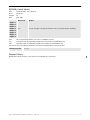

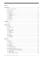


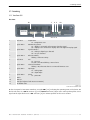

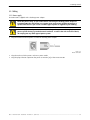

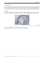


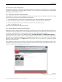
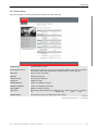
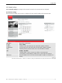


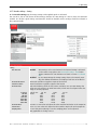

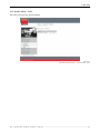
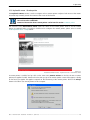
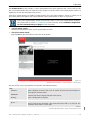
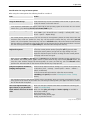
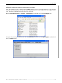


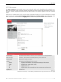


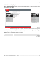
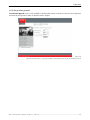


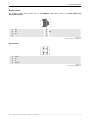


![OverView Control Manager user`s manual - operator [v04]](http://vs1.manualzilla.com/store/data/005659468_1-4c522981c7089838b286d7fbb1120c24-150x150.png)
![Overview cPR67 and cPR84 [v00]](http://vs1.manualzilla.com/store/data/005648847_1-d158a5d3d4b92d14c7a3179652b88ffd-150x150.png)


![FLM integration rod replacement + adjustment [v00]](http://vs1.manualzilla.com/store/data/005734078_1-ffddbeaec5f2fd08f6ea79cefb7ee063-150x150.png)