1
MTG1000 Trunk Gateway User Manual V2.0
MTG1000 User Manual
Revision Records
File Name
MTG1000 trunk gateway user manual
Document Version
2.0
Firmware Version
2.02.02.01
Date
03/05/2012
Revised by
Technical Support Department
MTG1000 User Manual
Content
1. Product Introduction ..................................................................................................................... 1
1.1 Overview ............................................................................................................................. 1
1.2 Equipment Structure ........................................................................................................... 2
1.2.1 Rear View ................................................................................................................. 2
1.2.2 Front View ................................................................................................................ 3
1.2.3 RJ-48c Line sequence .............................................................................................. 4
1.3 Functions and Features ....................................................................................................... 4
1.3.1 Protocol standard supported.................................................................................... 4
1.3.2 System Function ....................................................................................................... 4
1.3.3 Industrial standards supported ................................................................................ 5
1.3.4 General hardware specification ............................................................................... 5
2. Parameter Setting .......................................................................................................................... 6
2.1 Login ................................................................................................................................... 6
2.2 Web interface structure and navigation tree ...................................................................... 7
2.3 Status & Statistics ................................................................................................................ 9
2.3.1 System Information ................................................................................................ 10
2.3.2 E1/T1 Status ........................................................................................................... 11
2.3.3 PSTN Trunk Status ................................................................................................. 12
2.3.4 IP Trunk Status ....................................................................................................... 12
2.3.5 PRI Call Statistics................................................................................................... 13
2.3.6 SS7 Trunk Call Statistics ........................................................................................ 14
2.3.7 SIP Call Statistics ................................................................................................... 14
2.3.8 H.323 Call Statistics ................................................................................................ 14
2.4 Network............................................................................................................................. 15
2.5 PRI Config ........................................................................................................................ 16
2.5.1 PRI Parameter......................................................................................................... 16
2.5.2 PRI Trunk ................................................................................................................ 17
2.6 SS7 Config ........................................................................................................................ 18
2.6.1 SS7 Trunk ................................................................................................................ 18
2.6.2 SS7 MTP Link .......................................................................................................... 20
2.6.3 SS7 Circuit ............................................................................................................... 21
2.6.4 SS7 Circuit Maintain .............................................................................................. 22
2.6.5 Slave TG Management ........................................................................................... 23
2.7 PSTN Group Config.......................................................................................................... 24
2.7.1 E1/T1 Parameter..................................................................................................... 24
2.7.2 Coder Group ........................................................................................................... 25
2.7.3 Dial Plan................................................................................................................. 25
2.7.4 Dial Timeout .......................................................................................................... 27
2.7.5 PSTN Profile .......................................................................................................... 27
2.7.6 PSTN Group ........................................................................................................... 28
2.7.7 PSTN Group Management ..................................................................................... 29
2.8 SIP Config ......................................................................................................................... 30
MTG1000 User Manual
2.8.1 SIP Parameter ......................................................................................................... 30
2.8.2 SIP Trunk ............................................................................................................... 30
2.8.3 SIP Account............................................................................................................. 31
2.9 H323 Config ....................................................................................................................... 33
2.9.1 H.323 Parameter .................................................................................................... 33
2.9.2 H.323 Trunk ............................................................................................................ 34
2.10 IP Group Config ............................................................................................................... 35
2.10.1 IP Profile .............................................................................................................. 35
2.10.2 IP Group ............................................................................................................... 36
2.10.3 IP Group Management ......................................................................................... 36
2.11 Call Routing .................................................................................................................... 37
2.11.1 Routing Parameter ................................................................................................ 37
2.11.2 PSTN->IP Routing.................................................................................................. 37
2.11.3 PSTN->PSTN Routing ............................................................................................ 38
2.11.4 IP->PSTN Routing .................................................................................................. 39
2.11.5 IP->IP Routing ....................................................................................................... 40
2.12 Number Manipulation ..................................................................................................... 41
2.12.1 PSTN->IP Callee .................................................................................................... 42
2.12.2 PSTN->IP Caller ..................................................................................................... 43
2.13 Voice & Fax..................................................................................................................... 45
2.14 Management Parameter ................................................................................................... 47
2.14.2 SNMP Parameter .................................................................................................. 48
2.14.3 Data Backup ......................................................................................................... 49
2.14.4 Data Restore ......................................................................................................... 49
2.14.5 Version Information.............................................................................................. 49
2.14.6 Firmware Upload ................................................................................................. 50
2.14.7 Modify Password ................................................................................................. 50
2.14.8 Restart Device ...................................................................................................... 50
3. FAQ .............................................................................................................................................. 51
3.1 How to get the IP address if user modified or forgot the default IP? ............................... 51
3.2 If meet other questions, please from Dinstar website and download trouble
shootingV4.0 ........................................................................................................................... 51
4. Glossary ............................................................................................................................... 51
MTG1000 User Manual
1. Product Introduction
1.1 Overview
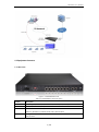
MTG1000 is a trunk gateway aimed at operators and call center, and used to help enterprise
to realize the evolution from the traditional PBX to voice IP. On the one hand, it supports
PRI/SS7 protocol and adopts standard T1/E1 trunk interface to realize docking with traditional
PBX. On the other hand, adopt standard SIP protocol docking with various soft switch to
ensure PSTN seamless access to IP voice/NGN network, and achieving VoIP/FoIP and more
value-added service. MTG1000 supports intelligent multiple trunk routing technology, makes
the operator easy to manage trunk routing by price optimum rule, and the automatic
switch-over between multiple trunk routing makes the network have high reliability.
MTG1000 has good call processing ability, and provides 4/8 T1/E1 interface. It is able to
handle a variety of signaling protocol and voice decoding. It supports the rich GUI
configuration, the user easily set and maintenance system. Mainly includes the following
kinds of models:
MTG1000-4E1
MTG1000-8E1
A typical network diagram shows the function of MTG1000 as below.
Figure 1-1-1 Application topology
1 / 55
MTG1000 User Manual
1.2 Equipment Structure
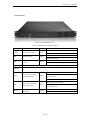
1.2.1 Rear View
Figure 1-2-1 MTG1000 Rear View
Table 1-2-1 MTG1000 Rear View Description
Interface
Description
PWR
Connecting the power adapter, 110~240VAC, 50~60HZ, 1.2A, double power
Port0-Port7
E1/T1 port, There are 8E1/T1 ports
FE0
The Service Ethernet Interface, standard 10/100BASE-TX Ethernet interfaces. Default IP
address is 192.168.1.111, default subnet mask is 255.255.255.0
FE1
Management Ethernet Interface. Default IP address is 192.168.11.1, default subnet mask is
255.255.255.0
2 / 55
MTG1000 User Manual
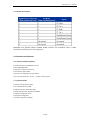
1.2.2 Front View
Figure 1-2-2 MTG1000 Front View
Table 1-2-2 MTG1000 Front View Description
LED
Function
Color
POWER
Power status indicator
Green
RUN
Register indicator
Green
ALM
RST
CONSOLE
The failure of device
indicator
Work Status
Off:Power is off
On: Power is on
Slow blinking: Unregister
Fast blinking: Register
Yellow
Off: Normal
On: Failed
Reset button, it is used to restart the device
RS232 console port: it can be used to debug and configure the device. The baud rate is 115200
bps.
Off:E1/T1 port connection normal
E1/T1
Indicating the connection
state of device E1/T1.
On: E1/T1 port connection and sending/ receiving
Green
message normal
Flash:E1/T1 port connection failed
LINK
Indicating the connection
state of the network
Off: Network connection failed
Green
On: Network connection normal, and 0 indicates FE0
and 1 indicates FE1
SPEED
Indicating the network
bandwidth
Yellow
Off:10Mbps bandwidth
On:100Mbps bandwidth
3 / 55
MTG1000 User Manual
1.2.3 RJ-48c Line sequence
MTG1000 trunk gateway adopts standard RJ-48C interface and impedance value is 120Ω.
Connected end device by cross lines sequence.
1.3 Functions and Features
1.3.1 Protocol standard supported
● Standard SIP /SIP-T/H.323/PRI/SS7 protocol
● NAT Traversing (STUN)
● Hypertext Transfer Protocol (HTTP)
● Domain Name System (DNS)
● Dynamic host configuration protocol (DHCP)
● ITU-T G.711A-Law/U-Law、G.723.1、G.729AB、iLBC (optional)
1.3.2 System Function
● Comfort Noise Generation (CNG)
● Voice Activity Detection (VAD)
● Adaptive (Dynamic) Jitter Buffer (DJB)
● DTMF mode: RFC 2833, SIP INFO and INBAND
● T.38/ Pass-Through FAX over IP
● HTTP/Telnet configuration
● Firmware upgrade by TFTP/Web
4 / 55
MTG1000 User Manual
1.3.3 Industrial standards supported
● Stationary use environment: EN 300 019: Class 3.1
● Storage environment: EN 300 019: Class 1.2
● Transportation environment: EN 300 019: Class 2.3
● Acoustic noise: EN 300 753
● CE EMC directive 2004/108/EC
● EN55022: 2006+A1:2007
● EN61000-3-2: 2006,
● EN61000-3-3: 1995+A1: 2001+A2: 2005
● EN55024: 1998+A1: 2001+A2: 2003
● Certifications: FCC, CE
1.3.4 General hardware specification
● Power supply: 220VAC, 1.2A
● Temperature: 0~40℃ (operational),-20~70℃(storage)
● Humidity: 10%~90%, no condensation
● Max power consumption: 25W
● Dimension (mm): 436*300*44
● Net Weight: 1.9 kg
5 / 55
MTG1000 User Manual
2. Parameter Setting
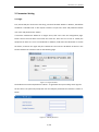
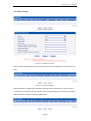
2.1 Login
First, device FE0 port connect PC with string, and then fill FE0 IP address in browser, FE0 default
IP address is 192.168.1.111. It will request customer to input user name and password. Default
user name and password are “admin”.
If customer modified the default IP or forgot the IP, that can’t enter the configuration page.
Please connect PC and device serial with the serial line. Enter the CLI to view or modify the
equipment IP. Here IP is set to 172.16.99.120. In addition, hold down the RST button to restart
the device, customer can regain the port’s default IP. Then enter the IP address of device in the
browser address bar. Customer will see the following page.
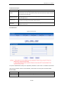
Figure 2-1-1 Login Interfaces
The default user name and password is "admin". To guarantee the system safety, when login for
the first time. The system will prompt the user to modify the password. The interface is shown as
below.
Figure 2-1-2 Modify Password
6 / 55
MTG1000 User Manual
Users through to traverse the left navigation tree, and can complete view, edit and configuration
device in the right configuration interface.
Figure 2-1-3 Description of System Information
2.2 Web interface structure and navigation tree
After entering configuration page, according to demand choose Chinese interface or English
interface, the default is English interface.
Figure 2-2-1 System Information
Users through to traverse the left navigation tree, and can complete view, edit and configuration
device in the right configuration interface.
7 / 55
MTG1000 User Manual
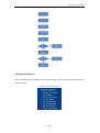
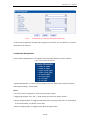
Figure 2-2-2 Navigation tree
MTG configuration flow chart below:
8 / 55
MTG1000 User Manual
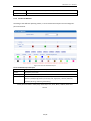
2.3 Status & Statistics
Open the operation of the navigation tree information node, and can view the device information
and state system.
Figure 2-3-1 Status & Statistics
9 / 55
MTG1000 User Manual
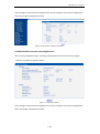
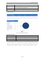
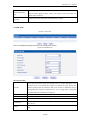
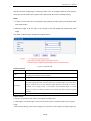
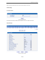
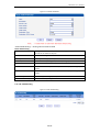
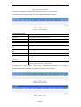
2.3.1 System Information
System information interface shows the general information and version information.
Figure 2-3-1 System Information
Table 2-3-1 System Information
MAC address
Hardware address of FE0 port
Service Ethernet Mode
Network mode of FE0, include: static and DHCP.
Service Ethernet Interface
Include: IP address, subnet mask, FE0 port default gateway
Management Ethernet Interface
Include IP address、subnet mask of FE1
DNS
DNS server IP address
System Up Time
Time elapsed from device power on to now
Traffic Statics
Total bytes of message received and sent by FE0 port
Equipment Type
Equipment type; this equipment is: MTG1000
Hardware Version
Hardware version of device
DSP Version
Digital signal processing chip driver version
Web Version
Version of current WEB interface of device
Software Version
Software version of device running currently
Built Time
The build time of current software version
10 / 55
MTG1000 User Manual
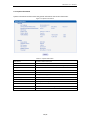
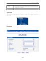
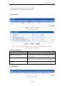
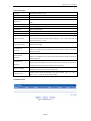
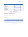
2.3.2 E1/T1 Status
Figure 2-3-2 E1/T1 Status
Table 2-3-2 Description of E1/T1 status
1. LOS Alarm: Signal loss alarm, this alarm is created when receiving is lost; please check
the physical connection whether disconnected.
2. RAI Alarm: Receive remote alarm indication, it is a signal transmitted in the outgoing
direction when a terminal determines that it has lost the incoming signal. Receiving
remote alarm indication (RAI) means the far-end equipment over the T1 line has a
problem with the signal it is receiving from the upstream equipment.
3. AIS Alarm: The Alarm Indication Signal (AIS) failure is declared when an AIS defect is
E1/T1 Port Status
detected at the input and the AIS defect still exists after the Loss of frame failure which is
caused by the unframed nature of the 'all-ones' signal is declared. The AIS failure is
cleared when the Loss Of Frame failure is cleared.
4. Disable: Means that this E1/T1 is not used.
5. ISDN/SS7 Signal Alarm: Means physical connection is normal, signaling link has
problem.
6. Active-OK: Means that physical connection and signaling link are normal.
Frame-Sync: Non voice channel, which used as a synchronization channel
Idle: Means this channel is idle, when the channel is enabled and the cable is connected
OK.
3.Signal: Signal channel
E1/T1Channel Status
4.Busy: Means this channel is occupied by voice
5. Fault: The channel is enabled but the cable is not connected.
6.Disable: Have not use this E1/T1 trunk
7.L-blocked:
Local blocked, means that communication can only be initiated from local
8.R-blocked:
11 / 55
MTG1000 User Manual
Remote blocked, means that communication can only be initiated from remote
9.B-blocked:
Both Sides blocked, means that the two sides cannot communication
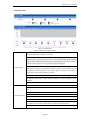
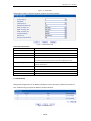
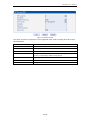
2.3.3 PSTN Trunk Status
Figure 2-3-3 PSTN Trunk Status
PSTN trunk status description:
1)PRI Link Status
PRI Trunk No.
The number of PRI trunk, each trunk corresponds to a PRI link
Trunk Name
Used to identify the name of the trunk
E1/T1Port No
Indicate the E1/T1 line occupied by the PRI trunk.
Link Status
Indicate whether the PRI link is established.
2)SS7 Link Status
SS7 Trunk No.
SS7 trunk number, each relay takes up a SS7 link.
Trunk Name
Used to identify the name of the trunk
E1/T1 Port No
Indicate the E1/T1 line occupied by the SS7 trunk.
Link Status
Indicate whether the SS7 link is established.
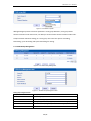
2.3.4 IP Trunk Status
Figure 2-3-4 SIP Trunk Status
IP trunk status
SIP Trunk No
The number of SIP trunk
Username
When SIP trunk is under registered mode, change the value in the configuration
shown in the account registration, If SIP trunk is under non-registered mode, the
value is meaningless, as '---'
12 / 55
MTG1000 User Manual
Trunk Mode
Peer and Access two modes
Register Status
Indicate the status of SIP trunk(access mode), register or unregister, when is under
peer to peer mode, the values is meaningless, as '---'
Link Status
Established and Fault status.
SIP Trunk No
The number of SIP trunk
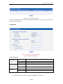
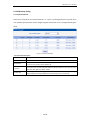
2.3.5 PRI Call Statistics
Figure 2-3-5 PRI Call Statistics description
PRI call statistics description
PRI Trunk No
The number of PRI trunk
Trunk Name
The name used to describe the PRI trunk
Current Calls
Number of lines that are being called currently
Accumulated Calls
Total number of calls from running start of system to current time.
ASR
The percent of calls completed in total calls.
This statistics page show the reasons for release of the call, including: Normal Call Clearing, Call
Rejected, User Busy, No User Response, No Circuit Available, Unassigned Number, Normal
Unspecified and others. Statistical information in an intuitive would be reflected on the pie char.
13 / 55
MTG1000 User Manual
2.3.6 SS7 Trunk Call Statistics
Figure 2-3-6 SS7 Trunk Call Statistics
The parameters of SS7 trunk call statistics are the same with PRI parameters. Please refer to PRI
trunk call statistics.
2.3.7 SIP Call Statistics
Figure 2-3-7 SIP Trunk Call Statistics
SIP call statistics description
SIP Trunk No
The number of SIP trunk
Trunk Name
The name used to describe the PRI trunk
Current Calls
Number of lines that are being called currently
2.3.8 H.323 Call Statistics
14 / 55
MTG1000 User Manual
Figure 2-3-8 H.323 Trunk Call Statistics
H. 323 call statistical parameters and SIP call statistical parameters is same, can be reference SIP
parameters statistics show.
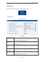
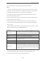
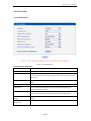
2.4 Network
Figure 2-4-1 Network Configuration
Network Configuration
IP address
Set FE0 port static IP address.
Subnet Mask
Fill in subnet mask
Default Gateway
Fill in default gateway
IP address
Set FE1 port static IP address
Subnet Mask
Fill in subnet mask
Primary DNS
Fill in DNS Server IP address.
Secondary DNS
The secondary DNS server is option.
Service Ethernet
Interface(FE0)
Management
Ethernet Interface
(FE1)
DNS Server
Ntoe:FE0 port IP and FE1 port IP should be set in different segments. After configure the
network address, and restart the gateway configuration to take effect.
15 / 55
MTG1000 User Manual
2.5 PRI Config
PRI configuration includes PRI parameter and PRI trunk configuration
Figure 2-5-1 PRI Config
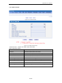
2.5.1 PRI Parameter
Figure 2-5-2 PRI Parameter
PRI parameter description
Calling Party
Numbering Plan
Calling Party Number
Type
Provide six plans: Unknown, ISDN/Telephony numbering plan, data numbering plan,
telegraph numbering plan, national standard numbering plan, private numbering plan.
The default is ISDN/Telephony numbering plan.
Six optional types are provided for calling party: Unknown, International number,
National number, Network special number, User number, Short code dialing. The
default option is Unknown.
Screening Indicator for
Four options available: User provider, no shield; User provide, check and send; User
Displaying Caller
provide, check and having failure; Network provide. The default option is: User
Number
provider, no shield.
Screening Indicator for
Four options available: User provider, no shield; User provide, check and send; User
No Displaying Caller
provide, check and having failure; Network provide. The default option is: User
Number
provider, no shield.
Called Party Numbering
Plan
Provide six plans: Unknown, ISDN/Telephony numbering plan, data numbering plan,
telegraph numbering plan, national standard numbering plan, private numbering plan.
The default is ISDN/Telephony numbering plan.
16 / 55
MTG1000 User Manual
Called Party Number
Type
Information Transfer
Capability
Six optional types are provided for called party: Unknown, International number,
National number, Network special number, User number, Short code dialing. The
default option is Unknown.
Support speech and 3.1khz audio. The default option is speech.
2.5.2 PRI Trunk
Figure 2-5-3 PRI Trunk
Users can add/delete/modify PRI trunk in this configuration option.
Figure 2-5-4 Add PRI Trunk
PRI trunk description
The number of PRI trunk; when user add PRI trunk, 0~7 number will appear in the
pull-down menu to be selected (the number here depends on E1/T1 physical port
Trunk No
number actually existed in equipment). After trunk number is established, filling in
corresponding port number in “E1/T1 Port No.”, so as to assign E1/T1 to designated
trunk; Each PRI trunk corresponds to a E1/T1 port.
Trunk Name
Description of PRI trunk
Channel ID
Channel ID of E1/T1 ports, this number definition generally starts from 0.
D-channel
Indicate whether E1/T1 supports D channel, the default is Yes.
E1/T1 Port No
Protocol
E1/T1 port number is numbered according to the physical position of E1/T1, it generally
starts from 0.
Interface type of PRI. There are two types are available: ISDN and QSIG; the default is
ISDN.
17 / 55
MTG1000 User Manual
Indicate PRI network property of E1/T1, it is divided into: “User side” and“Network side”.
Switch Side
When PRI loopback is carried out, the network properties of E1/T1 port at both receiving
and sending sides must be different.
Alerting Indication
The ring signal include Alerting and Progress
2.6 SS7 Config
SS7 configuration includes: SS7trunk, SS7 MTP Link, SS7 CIC, SS7 CIC Maintain and Slave TG
Management.
Figure 2-6-1 Add PRI Trunk
2.6.1 SS7 Trunk
Figure 2-6-2 SS7 Trunk
Figure 2-6-3 SS7 Trunk Add
18 / 55
MTG1000 User Manual
SS7 is a standard protocol to initiate a calling connection with SPC exchange.
Notes:
1. “Trunk No.” is a shared data, therefore, SS7 „Trunk No.‟ can't be the same as PRI “Trunk No.”
2. SPC length is 24bits when option “ANSI” or “ITU-CHINA” is selected in item “Standard Type”.
3. SPC length is 14bits when option “ITU” is selected in item “Standard Type”.
4. SPC Length represents the structure of OPC/DPC. SPC View Mode indicates which input
format is selected for OPC/DPC structure.
5. When SPC length is 24bits and 'Hex' are selected, the structure is like xyz, and x,y,z must be
hex number between 00-FF. eg., 33AA55.
6. When SPC length is 14bits and 'ITU Pointcode Structure' are selected, the structure is like
x-y-z, and x,z must be decimal number between 0-7, and y must be decimal number between
0-255. eg., 6-222-3.
7. When SPC length is 14bits and 'Hex' are selected, the structure is like xyz, and x/z is a 3 bit hex
number, y is a 8 bit hex number. eg., 202E(100 00000101 110).
SS7 trunk add
The number of SS7 trunk. Generally, a DPC will establish a SS7 trunk number
Select Trunk No
respectively, SS7 trunk number cannot be conflict with PRI trunk number. After
SS7 trunk is established, assign E1/T1 to SS7 trunk in “SS7 Circuit” option.
Trunk Name
Name of trunk, it can be edited to any name user want.
Protocol
SPC types: ITU-T (14 bit), ANSI (24 bit), ITU-CHINA (24 bit)
Protocol Type
Supported two protocol types: ISUP and TUP
SPC Format
Signaling Point Code format includes hexadecimal system and ITU pointcode
structure (decimal system)
OPC
Original Point Code
DPC
Destination Point Code
Service Type
SS7 service types: ISUP (ISDN User Part) and TUP (Telephone User Part).
Indicate the network property of SS7, including International Network,
International Spare, National Network, National Spare; the default is “National
Network Indicator
Network” (this type is used in China, USA, and Japan), “International Network”
is generally used in inter-office switch room; others will be selected according
to physical circumstances.
Note:
1. If protocol standard chose 'ANSI' or 'ITU-CHINA', and then the SPC length is 24 bits.
2. If protocol standard chose'ITU', and then the SPC length is 14 bits.
19 / 55
MTG1000 User Manual
3. SPC length performance on the OPC/DPC structure; SPC pattern instructions of the different
structure OPC/DPC input formats.
4. When the SPC length is 24 bits, and chosen ITU, OPC/DPC structure format is :x-y-z; x、y、z is
a number of 0-255, such as: 22-222-77
5. When the SPC length is 24 bits, and chosen Hex, OPC/DPC structure format is :xyz; x、y、z must
be Hex number of 00-FF, such as: 33AA55
6. When the SPC length is 24 bits, and chosen ITU, OPC/DPC structure format is : x-y-z;x、z must
be decimal value; y is decimal number 0-255, such as: 6-222-3
7. When the SPC length is 24 bits, and chosen Hex, OPC/DPC structure format is :xyz; x、z must
be three bitts hex value; y is 8 bitts hex value, such as:(202E)100 00000101 110
2.6.2 SS7 MTP Link
Figure 2-6-4 SS7 MTP Link
Figure 2-6-5 SS7 MTP Link Add
20 / 55
MTG1000 User Manual
SS7 MTP link description
Trunk No
It is consistent with foregoing “Trunk No” of SS7 trunk.
Equipment maximum support 2 signaling links, these two links share workload, when
Link No
one link fails, the other link will take over the load until restore from failure, and then
they will share the load again.
Signaling Link Code
E1/T1 Port No
Channel No
If a signaling point has established several signaling links, then the code of each signaling
link will begin from 0.
Indicate which E1/T1 this link is established on, it is stipulated that such numbering is
carried out according to the physical position of E1/T1.
Indicate time slot that link is established on. It is assigned to 1 or 16 for time slot, the
default is 16 time slot.
2.6.3 SS7 Circuit
Figure 2-6-5 SS7 Circuit
Figure 2-6-6 SS7 Circuit description
CIC (circuit identification code) is an important parameter of SS7 circuit. It should be confirmed
with service provider. If the CIC is mismatched, it will result in one-way voice communication.
SS7 Circuit Add
Trunk No
The “Trunk No.” here corresponds to the “Trunk No.” of SS7 trunk.
E1/T1 port No
Fill in the port number of E1/T1. Assign E1/T1 to selected SS7 trunk.
Start Channel
The start of SS7 channel trunk
21 / 55
MTG1000 User Manual
Start CIC No
An initial circuit number to this E1/T1 matches by both parties
Count
A total of 32 channels
2.6.4 SS7 Circuit Maintain
According to the different operating modes, 7 circuit maintenance objects into two categories:
ports and channel.
Figure 2-6-7 SS7 Circuit Maintain-E1/T1
SS7 Circuit Maintain-E1/T1 description
Operation Mode
There are port operation and channel optional
Port No
Display the port number
Protocol Type
TUP or ISUP
Status
There are 16 status with ports, each state corresponds to a color: activated, disable, fault,
RAI Alarm, ISDN/SS7 Signal Alarm, Frame-Sync, Idle, Signal, Busy, L-blocked, R-blocked,
B-blocked, Blocking, Unblocking and Resetting.
These ports can work in many ways: Select All, Invert, Clear, Block, Unblock, Reset and
Cancel.
22 / 55
MTG1000 User Manual
Figure 2-6-8 SS7 Circuit Maintain-Channel
If user wants to manage the channel, please select operation mode to channel.
Select current port, use will see port status and protocol type. The following will show the slot
and channel status. There are 16 kinds of channel states and each state corresponds to a color
2.6.5 Slave TG Management
Figure 2-6-9 Slave TG Management
When need to share 7 signaling point, add slave TG, so as to realize the multiple TG sharing a link.
23 / 55
MTG1000 User Manual
2.7 PSTN Group Config
2.7.1 E1/T1 Parameter
Clock source of E1/T1can be selected “Remote” or “Local”. If selecting E1/T1 port to port0, when
user modified port0, port0-3 will be changed together with port0. Port4-7 changed following the
port4.
Figure 2-7-1 E1/T1 Parameter
E1/T1 parameter description
Work Mode
E1/T1, the default is E1.
PCM Mode
PCM mode: A LAW and Mu LAW, the default is A LAW
Frame Mode
Line Code
Line Built Out
The frame modes of E1 are: DF, CRC-4, CRC4_ITU, the default is CRC-4; the frame modes
of T1 are: F12, F4, ESF, F72, the default is F4.
Line codes of E1 are: NRZ, CMI, AMI, HDB3, the default is HDB3. The Line codes of T1 are:
NRZ, CMI, AMI, B8ZS, the default is B8ZS.
Cable length. E1 lines docking, the environment will affect the E1 line signal strength,
signal strength according to (DB value) to select the long-term or short-term.
24 / 55
MTG1000 User Manual
2.7.2 Coder Group
Figure 2-7-2 Coder Group
Coder group description
ID standard for Voice ability, total with 8 groups, where 0 is the default group ID
Coder Group ID
number, the codec that equipment supports in the grouping will be displayed in 0
group. Default value cannot be modified.
Coder
Support 3 kinds of voice codec: G.711A/U/G.729/G.723
Payload Type Value
Each codec has a unique value, refer to RFC3551
Packetization Time(ms)
Rate(kbps)
Silence Suppression
Voice Codec packetization time, user can define different kinds of coding
and decoding minimum packetization time
Show the rate.
It is disabled by default. During talking, the bandwidth occupied by voice transmission
will be released automatically for silence party or when talk is paused.
ID standard for Voice ability, total with 8 groups, where 0 is the default group ID
Coder Group ID
number, the codec that equipment supports in the grouping will be displayed in 0
group. Default value cannot be modified.
2.7.3 Dial Plan
Figure 2-7-3 Dial Plan
25 / 55
MTG1000 User Manual
Dial plan used for configuring the receiving number, user can configure different prefix number,
these rules can be divided into 5 groups with a dial plan ID, where 0 is the default setting.
Notes:
1. In order to ensure each rule can take effect, long matching numbers (prefix) rule dial plan index
value need smaller.
2. Maximum length is 30, this value is the number of the total length and including the prefix
length.
Click “Add” to add dial plan, configuration page as follow:
Figure 2-7-4 Dial Plan Add
Dial Plan description
Dial Plan ID
Index
Prefix
The number to identify a dial plan
Dial plan priority rules take effect in accordance with dial plan index size, and not
according to the maximum number received.
Match number, "." representative of any number
The minimum receiving Number length (0 to 30). If receiving a number equal to the
minimum length greater than, less than equal to the maximum length, the number will be
Min Length
used to continue the call. If the maximum length determine the number to receive a
complete, will no longer receive a new number, and immediately began to number
analysis. If there are numbers continue to be received, the system will give up these
numbers.
Max Length
The largest received number length (0 to 30)
special version:
1. Dial plan can be backup and restore in management configuration.
2. “Min Length” and “Max Length” are equal to the total number of possible length minus the prefix
length.
3. When overlap dialing, called number length sure, and then the “Min Length” and “Max Length” will
26 / 55
MTG1000 User Manual
be set to the same value to accelerate connection rate.
4. Prefix configuration, compatible “digit map” mode.
2.7.4 Dial Timeout
Figure 2-7-5 Dial Timeout
Figure 2-7-6 Dial Timeout Add
Dial timeout description
Dial Time ID
The number to identify a dial timeout rule
Description
Description of dial timeout
Max Time for Collecting Prefix
Generally refer to the time from user dial first digit to harvest in
prefix number.
Time to Reach Min Length(after Prefix)
After receiving prefix number, the number has not yet reached the
length of the minimum receiving number, the length of timeout
Time to Reach Max Length(after Min
After receiving number, the number has reached the minimum
Length)
length, but not reached the maximum length of the dial timeout
2.7.5 PSTN Profile
27 / 55
MTG1000 User Manual
Figure 2-7-7 PSTN Profile
PSTN profile is used to configure PSTN call number rules and parameter.
Figure 2-7-8 PSTN Profile Add
PSTN profile add description
PSTN Profile ID
The number to the PSTN Profile
Description
Description of the PSTN Profile
Code Group ID
Refer to "Coder Group"
RFC2833 Payload Type
The item is 101 by default.
st
nd
rd
1 /2 /3 Tx DTMF Option
There are three ways to send DTMF: RFC2833/SIP INFO/ INBAND, in
accordance with the priority choice to send the configuration mode
Overlap Receiving
Not enabled by default, only user enables this feature, “Dial plan” and “Dial
timeout” would work.
Remove CLI
Default does not remove CLI
Play busy tone to PSTN
Equipment will play busy tone from IP to PSTN
PSTN Profile ID
The number to the PSTN Profile
Description
Description of the PSTN Profile
2.7.6 PSTN Group
PSTN group configuration can be different E1/T1ports or the same port in different time slots to
form a PSTN trunk group based on different channel selection.
Figure 2-7-9 PSTN Group
28 / 55
MTG1000 User Manual
Figure 2-7-10 PSTN Group Add
Adding PSTN group needs to fill three parameters: trunk group Numbers, trunk group Name.
Channel selection mode and at most, can add up to 16 set of data. Channel selection mode refers
to E1/T1 timeslot allocation strategy in a trunk group. There are four options: Ascending,
Descending, Cyclic Ascending and Cyclic Descending for routing.
2.7.7 PSTN Group Management
Figure 2-7-11 PSTN Group Management
Figure 2-7-12 PSTN Group Management Add
PSTN group management add
Group ID
PSTN group ID
Start E1
E1/T1 trunk group port number in the initial
End E1
Last a E1/T1 trunk group port number
Start Channel
The beginning of time slot, assigned a precise time slot for a group of trunk
End Channel
The end of time slot, assigned a precise time slot for a group of trunk
PSTN Profile ID
Refer to PSTN Profile
29 / 55
MTG1000 User Manual
When cross E1 port operation, don’t choose start/termination of the time.
2.8 SIP Config
2.8.1 SIP Parameter
Figure 2-8-1 SIP Parameter
The default Local SIP Port is 5060, and Local Domain set here can replace SIP account.
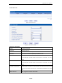
2.8.2 SIP Trunk
Figure 2-8-2 SIP Trunk
Figure 2-8-3 SIP Trunk Add
30 / 55
MTG1000 User Manual
SIP trunk description
Trunk No
The range of number is 1~99
Trunk Name
Description the trunk
Remote Address
IP address of remote platform interfacing with this equipment.
Remote Port
Q.931 port of SIP of remote platform interfacing with this equipment, the default is
5060
Outbound Proxy
SIP proxy IP address
Outbound Proxy Port
The default proxy port is 5060.
Local Domain
Refer to SIP parameter
Support SIP-T
Not the target configuration, the parameter is always no. it is for SS7.
Get Callee from
Received the called number from request domain or “To header” filed
Defined by IETF work group RFC3372, it is a standard used to establish remote
Register to Remote
communication between SIP and ISUP; the default is “Yes”; if SIP trunk does not
support, then set it to “No”.
Incoming SIP
There are two modes: IP address and Password. If user selects “password”, then
Authentication Type
password will be filled.
IP to PSTN Calls
Restriction
PSTN to IP Calls
Restriction
IP to PSTN Time
Restriction
Detect Trunk Status
Enable SIP Trunk
IP to PSTN side of the limitation on the number of calls; the range is 0~65535, the
default is no limitation; If Yes is selected, then input limitation number of calls in the
edit box appeared.
PSTN to IP side of the limitation on the number of calls; the range is 0~65535, the
default is no limitation; If Yes is selected, then input limitation number of calls in the
edit box appeared.
The default setting is disabled. If Enabled is selected, then user can edit the start
and stop time of prohibition time interval. Within this time interval, all calls from IP
to PSTN are prohibited. (Calls from PSTN to IP are not limited)
Detect the status of SIP trunk. If select it, the equipment will send HEARTBEAT
message to peer to make sure the link status is OK.
A switch used to enable this SIP trunk or not; user can select “Yes” or “No”,
when “No” is selected, this SIP trunk is invalid.
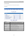
2.8.3 SIP Account
Figure 2-8-4 SIP Account
31 / 55
MTG1000 User Manual
Figure 2-8-5 SIP Account Add
This option is when the equipment is in the registered mode, used to manage SIP trunk account.
SIP trunk account
SIP Account ID
SIP Account Number, from 0-127
Description
Description of the SIP account
Binding PSTN Group
IP trunk group number, “any” indicates any trunk group
SIP Trunk No
The corresponding number and name of the SIP trunk
Username
SIP registration user name, the same SIP trunk can configure multiple SIP
accounts, corresponding to different trunk group ID
Password
Registered password
Confirm Password
Enter the password again.
Expire Time
SIP registration interval, default is 1800s
32 / 55
MTG1000 User Manual
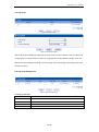
2.9 H323 Config
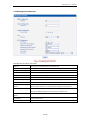
2.9.1 H.323 Parameter
Figure 2-9-1 H.323 Parameter
H.323 Parameter description
Call Mode
Supports faststart mode and conventional mode, faststart mode through faster.
Call Signal Port
Default call signal port is 1720
Enable H245 Tunneling
H. 245 is the multimedia communication control signaling protocol in H.323, and
its control of information running in H.245 control channels. Default, the channels
open forever.
DTMF Transfer Mode
Send mode has two: H.245 Alphabet and H.245 Signal, default is H.245 Alphabet
mode.
Start H245 on Fast Call
Whether establish H.245 agreement
Start H245 on
There are three steps building H.245: Call Connection, Signal Sending and
Proceeding, default is Connect.
Respond to Faststart on
When call mode is faststart mode, response phase is divided into three stages: Call
Connection, Signal Sending and Proceeding, default is Proceeding phase.
Start H.245 Negotiation
Whether establish H.245, terminal equipment will be sent H.245 negotiation news
Actively
consult.
Reset to default
Click the button to recover factory configuration.
configuration
33 / 55
MTG1000 User Manual
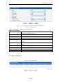
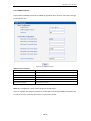
2.9.2 H.323 Trunk
Figure 2-9-2 H.323 Trunk
Figure 2-9-3 H.323 Trunk Add
H.323 trunk description
Trunk No.
Can add up to 63 trunk
Trunk Name
Named for the trunk
Remote IP
Equipment to end interface platform IP
Remote Port
Equipment to end interface platform port, default is 1720.
IP to PSTN Calls Restriction
IP to the side of the PSTN concurrent call the default without restriction. If select
Yes, and then fill in limited number of concurrent call in edit box. The max is
65535.
PSTN to IP Calls Restriction
PSTN to the side of the IP concurrent call the default without restriction. If select
Yes, and then fill in limited number of concurrent call in edit box. The max is
65535.
IP to PSTN Time Restriction
Default disables the function. If select enable, users will edit banning call of the
start time and end time. All call from IP to PSTN will be prohibited in this period
time.
Enable H.323 Trunk
After configuration, whether restart device.
34 / 55
MTG1000 User Manual
2.10 IP Group Config
The user can group manage SIP/H.323 trunk through IP packet configuration.
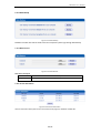
2.10.1 IP Profile
Figure 2-10-1 IP Profile
Figure 2-10-2 IP Profile Add
IP profile add
IP Profile ID
IP property identification number can be configured to 15 properties
Description
Description of the IP Profile
Declare RFC2833 in SDP
Default support
Support Early Media
Whether support Early Media(183). If select “Yes”, the called side to the early
media to provide ring back tone to the caller.
Ring back Tone to PSTN
IP-> PSTN call ring back tone player side, if setting to local, it will play from the
Originated from
equipment. If setting to IP , it will play by the called
Ring back Tone to IP Originated
PSTN->IP call ring back tone player side, if setting to local, it will play from the
from
equipment and set to PSTN, it will play by the called
Wait for RTP Packet from Peer
T.30 Expanded Type in SDP
If set to No, it will auto send RTP packets during the call and if set to Yes, it will
wait the RTP packet was sent by the back side first ,then send out RTP packets
T30 extended types in SDP: x-fax or fax
35 / 55
MTG1000 User Manual
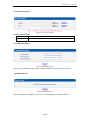
2.10.2 IP Group
Figure 2-10-3 IP Group
Figure 2-10-4 IP Group Add
Add the IP group including the IP group ID, IP group name, IP trunk selection. User can add a total
of 16 IP group. IP routing mod is to show in an IP group SIP time distribution strategy. There are
four options: Ascending, Descending, Cyclic ascending, Cyclic descending. (According to SIP trunk
number to choice)
2.10.3 IP Group Management
Figure 2-10-5 IP Trunk Group
IP trunk group description
Group ID
IP group ID
Index
The priority value of 0-15
Trunk Type
Currently only supports SIP, H.323 will be also supported in future
Trunk No
SIP trunk number
IP Profile ID
Refer to IP Profile
36 / 55
MTG1000 User Manual
2.11 Call Routing
2.11.1 Routing Parameter
Figure 2-11-1 Routing Parameter
Inbound and outbound call routing configuration
The key steps how to Configure routing:
The more accurate routing configuration, index values should be smaller.
“Any” and "." are useful; suggesting configuration, to avoid cannot match the routing.
2.11.2 PSTN->IP Routing
Figure 2-11-2 PSTN->IP Routing
37 / 55
MTG1000 User Manual
Figure 2-11-3 PSTN->IP Add
“PSTN -> IP Routing”: Routing Call from PSTN to IP
PSTN->IP routing description
Index
Routing index number (0 ~ 255) , “PSTN->IP Routing” priority rule is according to
the index to set. Reference dial plan.
Description
Describe the routing
Source Type
Source type is PSTN group or PRI/SS7 trunk.
PSTN Group
Refer to “PSTN Group Config”, any means any trunk group.
Callee Prefix
Callee number matches prefix number, "." Is a wildcard, representing any callee
number
Caller Prefix
Caller number matches prefix number, "." Is a wildcard, representing any caller
number
Destination Type
Destination type is IP group or SIP/H.323 trunk.
Destination IP Group
Refer to “IP Group”
Trunk Type
Trunk type means IP side trunk type-SIP/H.323.
Trunk No.
Trunk number
2.11.3 PSTN->PSTN Routing
Figure 2-11-4 PSTN->PSTN Routing
38 / 55
MTG1000 User Manual
Figure 2-11-5 PSTN->PSTN Add
“PSTN->PSTN Routing”:Routing Call from PSTN to PSTN
PSTN->PSTN Routing
Index
Routing index number (0 ~ 255) , “PSTN->IP Routing” priority rule is according to
the index to set. Reference dial plan.
Description
Describe the routing
Source Type
Source type is PSTN group or PRI/SS7 trunk.
PSTN Group
Refer to “PSTN Group Config”, any means any trunk group.
PSTN Trunk
Reference “PRI Trunk” or “SS7 Trunk”
Callee Prefix
Callee number matches prefix number, "." Is a wildcard, representing any callee
number
Caller Prefix
Caller number matches prefix number, "." Is a wildcard, representing any caller
number
Destination Type
Destination type is PSTN group or SIP/H.323 trunk.
Destination PSTN Group
Refer to “PSTN Group Config”
2.11.4 IP->PSTN Routing
Figure 2-11-6 IP->PSTN Routing
39 / 55
MTG1000 User Manual
Figure 2-11-7 IP->PSTN Routing
“IP -> PSTN Routing”: Routing Call from IP to PSTN
IP->PSTN routing configuration and PSTN->PSTN routing configuration are similar, the only
difference is PSTN destination group.
2.11.5 IP->IP Routing
Figure 2-11-8 IP->IP Routing
Figure 2-11-9 IP->IP Add
40 / 55
MTG1000 User Manual
IP->IP routing configuration and PSTN->IP configuration are similar. The only difference is that the
destination is the IP group.
2.12 Number Manipulation
Select “Number Manipulation” in navigation tree, the display interface is shown as below:
Figure 2-12-1 Number Manipulation
"Number Manipulation” is used to replace numbers. User can replace and remove the inbound
and outbound calling / called number.
Notes:
1. The more precise configuration, index values should be smaller.
2. Suggesting configure “Any” and “.”, avoid missing the call for the replace number。
3. When configuring data, it is suggested that index starts from large index value, to avoid adding
an exact match data, not directly use the data.
4. When configuring data, it is suggested that keep using index value.
41 / 55
MTG1000 User Manual
2.12.1 PSTN->IP Callee
Figure 2-12-2 PSTN->IP Callee
Figure 2-12-3 PSTN->IP Callee Add
“PSTN->IP Callee”:Replace the called number from PSTN
PSTN->IP destination number
Index
Index number (0 ~ 127)
Description
Describe the transformation of the number
PSTN Group
Refer to “PSTN Group”, “any” means any trunk group
Callee Prefix
Called number prefix, “.” mean any called number
Caller Prefix
Caller number prefix, “.” Mean any caller number
Number of Digits to Strip from left
Remove the called number digits from the left
Number of Digits to Strip from right
Remove the called number digits from the right
Prefix to be Add
Add a called number prefix
Suffix to be Add
Add a called number suffix
Number of Digits to Reserve from
Starting from the right to retain the called number digits
Right
42 / 55
MTG1000 User Manual
2.12.2 PSTN->IP Caller
Figure 2-12-4 PSTN->IP Caller
Figure 2-12-5 PSTN->IP Caller Add
PSTN->IP Callee configuration parameters and IP->PSTN Caller configuration parameters are the
same.
Figure 2-12-6 PSTN->PSTN Callee
PSTN->PSTN Callee configuration parameters with the above is basically same, only more of a
“number type” parameter. Common number types are: Not Configured, Unknown, International,
National, Network Specific, Subscriber, Abbreviated.
43 / 55
MTG1000 User Manual
Figure 2-12-7 PSTN->PSTN Caller
"Presentation indicator" parameter used to indicate the status of the operation.
The operation of the option the right are: Not configured, Allowed, Restricted.
Figure 2-12-8 IP->PSTN Callee
IP->PSTN callee description
Index
Index number (0 ~ 127)
Description
Describe the transformation of the number
IP Group
Refer to “IP Group”, “any” means any trunk group
Callee Prefix
Called number prefix, “.” means any called number
Caller Prefix
Caller number prefix, “.” Means any caller number
Number of Digits to Strip from
Remove the called number digits from the left
left
Number of Digits to Strip from
Remove the called number digits from the right
right
Prefix to be Add
Add a called number prefix
Suffix to be Add
Add a called number suffix
Number of Digits to Reserve
Starting from the right to retain the called number digits
from Right
Number Type
Common number types are: Not Configured, Unknown, International, National,
Network Specific, Subscriber and Abbreviated.
“IP->PSTN Caller”, “IP->IP Callee”, “IP->IP Caller” configuration parameters in the previous
number manipulation rules have been mentioned, please refer that section.
Figure 2-12-9 IP->PSTN Caller
44 / 55
MTG1000 User Manual
Figure 2-12-10 IP->IP Callee
Figure 2-12-11 IP->IP Caller
2.13 Voice & Fax
Figure 2-13-1 Voice & Fax
45 / 55
MTG1000 User Manual
Voice & Fax description
Voice Parameter
Disconnect Call when no RTP
When selected “Yes”, detected call’s silence time
packet
longer than silence timeout that for a long time
not received RTP packets, then hangup the call.
Period without RTP packet
The maximum time length of silence
PSTN in Gain
Incoming PSNT gain
IP in Gain
Incoming IP gain
Timeout of no
Call from PSTN
Call timeout of no answer from PSTN
answer
Call from IP
Call timeout of no answer from IP
Two modes are provided: T.38/Pass-through;
Fax Mode
Fax Parameter
Data & Fax Control
DTMF Parameter
default option is T.38.
Fax Tx Gain
Gain of sending a fax
Fax Rx Gain
Gain of receiving a fax
Packet time
Data packing duration
Redundant frame in packet
The length of frame in RTP packet
Data
Whether to allow the control of voice data
Fax
Whether to allow the control of fax
Continuous time
The level of a frequency duration
The time interval between two different
Signal interval
frequency signals
Threshold for detection
Frequency detection threshold
46 / 55
MTG1000 User Manual
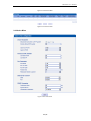
2.14 Management Parameter
Figure 2-14-1 Management Parameter
Management parameter description
WEB Port
Listening port of local WEB service, the default is 80.
Telnet Port
Listening port of local Telnet service, the default is 23.
Syslog Enable
The default is “No”.
Server Address
Address for saving system log
Syslog Level
None, Debug, Notice, Warning, Error
Send CDR
Whether send Call Detail Record
Qos Type
There are three options: none, TOS and DS. TOS only supports IPv4.
NTP Enable
Simple Network Management Protocol is enabled or not; the default is Yes.
Primary NTP server
The Primary IP address of SNMP management host computer. The host computer
Address
of the IP address will carry out monitoring and management to equipment.
Primary NTP server Port
The port that managed device provides trap message (it is generally alarm
message) to SNMP management host computer, the default is 123.
Secondary NTP server
The Secondary IP address of SNMP
Address
Sync Interval
Time interval of check
Time Zone
The time zone of local
47 / 55
MTG1000 User Manual
2.14.2 SNMP Parameter
Simple Network Management Protocol (SNMP) is application layer protocol, and used to manage
communication line.
Figure 2-14-3 SNMP Parameter
SNMP Parameter description
SNMP Enable
Whether enable SNMP function
SNMP Manager Address
Network management server IP address
Trap Port
Default trap port is 162
Read-only Community String
Define a read-only community
Read/Write Community String
Define a read/write community
Trap Community String
Define trap community
Note: After configuration, please restart equipment to take effect.
Users can manage and configure gateway on remote NM server through SNMP configuration. But
in order to security, recommend this option to open when needed.
48 / 55
MTG1000 User Manual
2.14.3 Data Backup
Figure 2-14-4 Data Backup
Database and dial rules will be saved to the local computer system logs through data backup.
2.14.4 Data Restore
Figure 2-14-5 Data Restore
Data restore description
Database
Click "Browse" to select the Database file, and then click "Restore".
Dial plan
Click "Browse" to select the Dial plan file, and then click "Restore".
2.14.5 Version Information
Figure 2-14-6 Version Information
Version information description version and built time of program, database and web file.
49 / 55
MTG1000 User Manual
2.14.6 Firmware Upload
Figure 2-14-7 Firmware Upload
Firmware upload description
Software
Click "Browse" to select the firmware, and then click "Upload".
Web
Click "Browse" to select the Web software, and then click "Upload".
2.14.7 Modify Password
Figure 2-14-8 Modify Password
After entering configuration page, please modify password to ensure the system security.
2.14.8 Restart Device
Figure 2-14-9 Restart Device
If user click Restart, a message ("Are you sure?") will be popped up, and then click OK.
50 / 55
MTG1000 User Manual
3. FAQ
3.1 How to get the IP address if user modified or forgot the default IP?
There are one way to get the IP address:
1) Connect the CONSOLE with your PC Serial Port. The baud rate is 9600 bps. The user name and
password is "admin". When users logged in system, and then run command "show int" for
getting the IP.
Please refer to http://www.dinstar.com/service/faq_145.aspx
3.2 If meet other questions, please from Dinstar website and download trouble
shootingV4.0.URL is: http://www.dinstar.com/service/Training.aspx
4. Glossary
PRI: Primary rate interface
DND: Do-not-Disturb
FMC: Fixed Mobile Convergence
SIP: Session Initiation Protocol
DTMF: Dual Tone Multi Frequency
USSD: Unstructured Supplementary Service Data
PSTN:Public Switched Telephone Network
STUN: Simple Traversal of UDP over NAT
IVR: Interactive Voice Response
IMSI: International Mobile Subscriber Identification Number
IMEI: International Mobile Equipment Identity
DMZ: Demilitarized Zone
51 / 55


![LS5105 Document No 2 [PDF 1MB] - Australian Electoral Commission](http://vs1.manualzilla.com/store/data/005655823_1-2458abda02bbd8390d0ac9ba8bd86ac6-150x150.png)