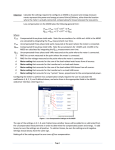
1
M870D Remote Display Manual September 30, 2009 ML0027 Document Revision C © 2009 by Bitronics, LLC TABLE OF CONTENTS M870D FIRMWARE REVISIONS................................................................................... iii 70 SERIES MANUAL SET............................................................................................. iii INSTALLATION AND MAINTENANCE ......................................................................... iv WARRANTY AND ASSISTANCE.................................................................................. iv Authorized representative in the European Union ..................................................... v COPYRIGHT NOTICE..................................................................................................... v TRADEMARKS ............................................................................................................... v SAFETY SECTION ....................................................................................................... vii WARNING: EMISSIONS - CLASS A DEVICE (N55011).............................................. ix Decommissioning and Disposal ................................................................................. ix 1.0 Introduction ............................................................................................................ 1 1.1 1.2 1.3 1.4 1.5 Features ..................................................................................................................................................1 Specifications ..........................................................................................................................................1 Environmental..........................................................................................................................................1 Physical ...................................................................................................................................................2 Standards and Certifications ...................................................................................................................4 2.0 Installation .............................................................................................................. 6 2.1 2.2 2.3 2.4 2.5 2.6 2.7 Initial Inspection.......................................................................................................................................6 Instrument Mounting ................................................................................................................................6 Surge Protection......................................................................................................................................7 Overcurrent Protection ............................................................................................................................7 Supply/Mains Disconnect ........................................................................................................................8 Power Supply Connections .....................................................................................................................8 Cleaning ..................................................................................................................................................8 3.0 SETUP ..................................................................................................................... 9 3.1 Communications Connections.................................................................................................................9 3.2 Setup Mode ...........................................................................................................................................12 3.3 Measurement Screens ..........................................................................................................................13 3.4 Operation ...............................................................................................................................................15 3.4.1 Overview .........................................................................................................................................15 3.4.2 Keypad ............................................................................................................................................16 3.4.3 Tx/Rx LED .......................................................................................................................................16 3.5 RS232 Service Port ................................................................................................................................16 4.0 Troubleshooting .................................................................................................... 17 4.1 Error/Informational Messages ................................................................................................................17 5.0 Firmware Upgrades ............................................................................................... 17 ML0027 September 30, 2009 ii Copyright 2009 Bitronics, LLC M870D FIRMWARE REVISIONS Display v1.01.0 v1.02.0 v1.04.0 v1.05.0 v1.06.0 v1.07.0 v1.08.0 Description Initial Release Update Update – Baud rate max 38400 Update – Setup Config. saved to EEPROM Update – Bug fix Update – Changed bootup text to AREVA M570D release, power up sequence Bootloader v1.00.0 v1.01.0 Description Initial Release Update Date 4/23/02 7/25/02 11/01/02 6/03/03 9/15/03 3/05/04 10/07/05 Date 4/23/02 7/25/02 70 SERIES MANUAL SET ML0021 M87X User Manual ML0022 70 Series UCA® Object Model ML0024 M87X Modbus Plus Module & Protocol ML0025 70 Series Modbus Protocol ML0026 70 Series DNP3 Protocol ML0027 M870D Remote Display Manual ML0032 M57X User Manual ML0033 M570Dx Remote Display Manual ML0034 70 Series IEC 61850 Protocol Manual ML0027 September 30, 2009 iii Copyright 2009 Bitronics, LLC CERTIFICATION Bitronics LLC certifies that the calibration of our products is based on measurements using equipment whose calibration is traceable to the United States National Institute of Standards Technology (NIST). INSTALLATION AND MAINTENANCE Bitronics LLC products are designed for ease of installation and maintenance. As with any product of this nature, installation and maintenance can present electrical hazards and should be performed only by properly trained and qualified personnel. If the equipment is used in a manner not specified by Bitronics LLC, the protection provided by the equipment may be impaired. In order to maintain UL recognition, the following Conditions of Acceptability shall apply: a) Terminals and connectors that shall be connected to hazardous live voltages are restricted to non-field wiring applications only. b) After installation, all hazardous live parts shall be protected from contact by personnel or enclosed in a suitable enclosure. WARRANTY AND ASSISTANCE This product is warranted against defects in materials and workmanship for a period of thirty-six (36) months from the date of their original shipment from the factory. Products repaired at the factory are likewise warranted for eighteen (18) months from the date the repaired product is shipped, or for the remainder of the product's original warranty, whichever is greater. Obligation under this warranty is limited to repairing or replacing, at our designated facility, any part or parts that our examination shows to be defective. Warranties only apply to products subject to normal use and service. There are no warranties, obligations, liabilities for consequential damages, or other liabilities on the part of Bitronics LLC except this warranty covering the repair of defective materials. The warranties of merchantability and fitness for a particular purpose are expressly excluded. For assistance, contact Bitronics LLC at: Telephone: Fax: Email: Website: 610.997.5100 610.997.5450 [email protected] www.novatechweb.com/bitronics Shipping: 261 Brodhead Road Bethlehem, PA 18017-8698 USA ML0027 September 30, 2009 iv Copyright 2009 Bitronics, LLC AUTHORIZED REPRESENTATIVE IN THE EUROPEAN UNION NovaTech Europe BVBA Kontichsesteenweg 71 2630 Aartselaar Belgium T +32.3.458.0807 F +32.3.458.1817 E [email protected] COPYRIGHT NOTICE This manual is copyrighted and all rights are reserved. The distribution and sale of this manual is intended for the use of the original purchaser or his agents. This document may not, in whole or part, be copied, photocopied, reproduced, translated or reduced to any electronic medium or machine-readable form without prior consent of Bitronics LLC, except for use by the original purchaser. The product described by this manual contains hardware and software that is protected by copyrights owned by one or more of the following entities: Bitronics LLC, 261 Brodhead Road, Bethlehem, PA 18017; VentureCom, Inc., Five Cambridge Center, Cambridge, MA 02142; SISCO, Inc., 6605 192 Mile Road, Sterling Heights, MI 48314-1408; General Software, Inc., Box 2571, Redmond, WA 98073; Schneider Automation, Inc., One High Street, North Andover, MA 01845; Triangle MicroWorks, Inc., 2213 Middlefield Court, Raleigh, NC 27615 Greenleaf Software Inc., Brandywine Place, Suite 100, 710 East Park Blvd, Plano, TX 75074 TRADEMARKS The following are trademarks or registered trademarks of Bitronics LLC: The Bitronics logo Bitronics PowerPlex Triplex Triple-II MultiComm PowerServe SubCycle Technology SubCycleStuf The following are trademarks or registered trademarks of AREVA T&D Inc. AREVA T&D the AREVA logo MiCOM The following are trademarks or registered trademarks of the DNP User's Group: DNP DNP3 The following are trademarks or registered trademarks of the Electric Power Research Institute (EPRI): UCA The following are trademarks or registered trademarks of Schneider Automation, Inc.: MODSOFT Modicon Modbus Plus Modbus Compact 984 PLC The following are trademarks or registered trademarks of VentureCom, Inc.: ML0027 September 30, 2009 v Copyright 2009 Bitronics, LLC Phar Lap the Phar Lap logo The following are trademarks or registered trademarks of Systems Integration Specialists Company, Inc. (SISCO): SISCO MMS-EASE Lite AX-S4MMS The following are trademarks or registered trademarks of General Software, Inc.: General Software the GS logo EMBEDDED BIOS Embedded DOS The following are trademarks or registered trademarks of the PCI Industrial Computer Manufacturers Group: CompactPCI PICMG the CompactPCI logo the PICMG logo ML0027 September 30, 2009 vi Copyright 2009 Bitronics, LLC SAFETY SECTION This Safety Section should be read before commencing any work on the equipment. Health and safety The information in the Safety Section of the product documentation is intended to ensure that products are properly installed and handled in order to maintain them in a safe condition. It is assumed that everyone who will be associated with the equipment will be familiar with the contents of the Safety Section. Explanation of symbols and labels The meaning of symbols and labels that may be used on the equipment or in the product documentation is given below. Installing, Commissioning and Servicing Equipment connections Personnel undertaking installation, commissioning or servicing work on this equipment should be aware of the correct working procedures to ensure safety. The product documentation should be consulted before installing, commissioning or servicing the equipment. Terminals exposed during installation, commissioning and maintenance may present a hazardous voltage unless the equipment is electrically isolated. If there is unlocked access to the equipment, care should be taken by all personnel to avoid electric shock or energy hazards. ML0027 September 30, 2009 vii Copyright 2009 Bitronics, LLC Voltage and current connections should be made using insulated crimp terminations to ensure that terminal block insulation requirements are maintained for safety. To ensure that wires are correctly terminated, the correct crimp terminal and tool for the wire size should be used. Before energizing the equipment, it must be grounded (earthed) using the protective ground (earth) terminal, or the appropriate termination of the supply plug in the case of plug connected equipment. Omitting or disconnecting the equipment ground (earth) may cause a safety hazard. The recommended minimum ground (earth) wire size is 2.5 mm2 (#12 AWG), unless otherwise stated in the technical data section of the product documentation. Before energizing the equipment, the following should be checked: 1. Voltage rating and polarity 2. CT circuit rating and integrity of connections 3. Protective fuse rating 4. Integrity of ground (earth) connection (where applicable) 5. Equipment operating conditions The equipment should be operated within the specified electrical and environmental limits. Current transformer circuits Do not open the secondary circuit of a live CT since the high voltage produced may be lethal to personnel and could damage insulation. External resistors Where external resistors are fitted to relays, these may present a risk of electric shock or burns, if touched. Battery replacement Where internal batteries are fitted, they should be replaced with the recommended type and be installed with the correct polarity, to avoid possible damage to the equipment. Insulation and dielectric strength testing Insulation testing may leave capacitors charged up to a hazardous voltage. At the end of each part of the test, the voltage should be gradually reduced to zero, to discharge capacitors, before the test leads are disconnected. ML0027 September 30, 2009 viii Copyright 2009 Bitronics, LLC WARNING: EMISSIONS - CLASS A DEVICE (N55011) This is a Class A industrial device. Operation of this device in a residential area may cause harmful interference, which may require the user to take adequate measures. DECOMMISSIONING AND DISPOSAL 1. Decommissioning The auxiliary supply circuit in the relay may include capacitors across the supply or to ground (earth). To avoid electric shock or energy hazards, after completely isolating the supplies to the relay (both poles of any dc supply), the capacitors should be safely discharged via the external terminals before decommissioning. 2. Disposal It is recommended that incineration and disposal to watercourses is avoided. The product should be disposed of in a safe manner. Any products containing batteries should have them removed before disposal, taking precautions to avoid short circuits. Particular regulations within the country of operation may apply to the disposal of lithium batteries. ML0027 September 30, 2009 ix Copyright 2009 Bitronics, LLC 1.0 INTRODUCTION The M870D Remote Display connects to 70 Series IEDs through one of the serial communications ports. The M870D is designed to provide a convenient way to view measurements made by the 70 Series IEDs. A maximum of 64 user-configurable measurement screens can be displayed. The instrument can be set to display a single screen continually or automatically scroll through all available screens. Additionally, the user may manually step through all available screens. All of the screens can be scrolled. 1.1 Features Rugged Bitronics design Bright LED display, 3 lines of 5 digits and a one line, 8 character alphanumeric Standard 4” round mounting Configurable RS232 or RS485 communication PC based configuration tool for quick setup Front panel service port Front panel Demand and Energy reset (if enabled) 1.2 Specifications Display: 3 lines of 5 digits, Red LED, 0.56” High 1 line by 8 character alphanumeric, Red LED, 0.11” High User Interface: 4 pushbuttons Communication: Selectable RS232 or RS485 (4-wire), full duplex 9600, 19200, or 38400 baud 8 bit, No parity, 1 stop bit Distance: 50 ft. (15m) RS232, 4000 ft. (1200m) RS485 Addressability: Display Addresses 1 .. 15 Power Supply Requirements: Nominal: 24-250Vdc, 69-240Vac (50/60Hz) Operating Range: 20-300Vdc, 55-275Vac (45-65Hz) Burden: 11VA max, 4W max Weight (typical) : 1.25 lbs (0.57 kg) 1.3 Environmental Operating Temperature: -40 to 70degC Humidity: 0-95% non-condensing ML0027 September 30, 2009 1 Copyright 2009 Bitronics, LLC Installation Category: IC III (Distribution Level), Pollution Degree 2 (See Definitions, page 2) Enclosure Protection: (to IEC 60529: 1989) IP52 – Front Panel, IP20 – Rear Ratings are applicable for enclosure category 2. (see Definitions, below) Altitude: Up to and including 2000m above sea level Intended Use: Indoor; Indoor/Outdoor use when mounted in an appropriately rated protective enclosure to NEMA or IP protection classifications, as required for the installation. 1.4 Physical Connections: 3 pin removable terminal block for power inputs, accepts 2612AWG wire (0.15-3.3mm2), or terminal lugs up to 0.325” (8.25mm) wide. Recommended minimum wire size is #18 AWG (0.5mm2). Recommended torque rating for the terminal block wire fasteners is 10 in-lbs (1.13N-m). Precautions must be taken to prevent shorting of lugs at the terminal block. A minimum distance of 0.1" (2.5mm) is recommended between un-insulated lugs to maintain insulation requirements. Standard 0.200” (5.08mm) header socket accepts other standard terminal types. 6 pin removable terminal block for communications, accepts 26-12AWG wire. Standard 0.200” (5.08mm) header socket accepts other standard terminal types. The recommended torque rating for the terminal block wire fasteners is 4.4 in-lbs (0.5N-m). Standard 9 pin RS232 for service port Package: 4.5” square faceplate requires 4” round cutout for mounting. Definitions: Enclosure Category 2: Enclosures where no pressure difference relative to the surrounding air is present. Installation Category (Overvoltage Category) III: Distribution Level, fixed installation, with smaller transient overvoltages than those at the primary supply level, overhead lines, cable systems, etc. Pollution: Any degree of foreign matter, solid, liquid, or gaseous that can result in a reduction of electric strength or surface resistivity of the insulation. Pollution Degree 2: Only non-conductive pollution occurs except that occasionally a temporary conductivity caused by condensation is to be expected. ML0027 September 30, 2009 2 Copyright 2009 Bitronics, LLC ML0027 September 30, 2009 3 Copyright 2009 Bitronics, LLC 1.5 Standards and Certifications UL/CSA Recognized, File Number E164178 UL61010B1, 1st edition; CAN/ CSA No. 22.2 No, 1010-1-92 If applicable, the CE mark must be prominently marked on the case label. European Community Directive on EMC 2004/108/EC, (replaced former directive 89/336/EEC amended by 92/31/EEC, 93/68/EEC, 98/13/EC European Community Directive on Low Voltage 2006/95/EC (replaces former directive 73/23/EEC amended by 93/68/EEC) Product and Generic Standards The following generic standards were used to establish conformity: Low Voltage (Product Safety): EN 61010-1: 2001 EMC: EN 61326-1: 2006, EN 61000-6-2: 2005, EN 61000-6-4 : 2007 (EN 50081-2: 1993 has been superseded). Radiated Emissions Electric Field Strength EN 55011: 2007 / A2: 2007 (supersedes EN 55011: 1998 / A1:1999) Group 1, Class A Frequency: 30 - 1000 MHz AC Powerline Conducted Emissions EN 55011: 2007 / A2: 2007 (supersedes EN 55011: 1998 / A1:1999) Group 1, Class A Frequency: 150 kHz – 30 MHz Electrostatic Discharge (ESD) EN 61000-4-2: 1995 / A1: 1998: / A2: 2001 Discharge voltage: ± 8 KV Air; ± 4 KV Contact Immunity to Radiated Electromagnetic Energy (Radio Frequency) EN 61000-4-3: 2006 / A1: 2008 Class III (supersedes EN 61000-4-3: 2002 & EN61000-4-3: 2002 / A1:2002; and ENV 50204: 1996, on Immunity to Radiated Electromagnetic Energy -Digital Radio Telephones, 900MHz & 1890MHz). Frequency: 80 - 1000 MHz Amplitude: 10.0 V/m Modulation: 80% AM @ 1 kHz Frequency: 1400 - 2000 MHz Amplitude: 3.0 V/m Modulation: 80% AM @ 1 kHz Frequency: 2000 - 2700 MHz Amplitude: 1.0 V/m Modulation: 80% AM @ 1 kHz Electrical Fast Transient / Burst Immunity EN 61000-4-4: 2004 (supersedes EN 61000-4-4: 1995) Burst Frequency: 5 kHz Amplitude, AC Power Port ± 4 KV Amplitude, Signal Port: ± 2 KV ML0027 September 30, 2009 4 Copyright 2009 Bitronics, LLC Current/Voltage Surge Immunity EN 61000-4-5: 2006 (supersedes EN 61000-4-5: 1995) Open Circuit Voltage: 1.2 / 50 s Short Circuit Current: 8 / 20 s Amplitude, AC Power Port: 2 KV common mode, 1 KV differential mode Amplitude, I/O Signal Port: 1 KV common mode Immunity to Conducted Disturbances Induced by Radio Frequency Fields EN 61000-4-6: 2007 (supersedes EN 61000-4-6: 1996) Level: 3 Frequency: 150 kHz – 80 MHz Amplitude: 10 V rms Modulation: 80% AM @ 1 kHz AC Supply Voltage Dips and Short Interruptions EN 61000-4-11: 2004 (supersedes EN 61000-4-11: 1994) ML0027 September 30, 2009 5 Copyright 2009 Bitronics, LLC 2.0 INSTALLATION WARNING - INSTALLATION AND MAINTENANCE SHOULD ONLY BE PERFORMED BY PROPERLY TRAINED OR QUALIFIED PERSONNEL. 2.1 Initial Inspection Bitronics instruments are carefully checked and "burned in" at the factory before shipment. Damages can occur, however, so please check the instrument for shipping damage as it is unpacked. Notify Bitronics LLC immediately if any damage has occurred, and save any damaged shipping containers. 2.2 Instrument Mounting The instrument may be mounted on a 19" Rack panel if desired. Three units will fit side by side on a standard 5.25" high panel. See Figure 2 for panel cutout dimensions. The unit should be mounted using the four #10-32 studs attached to the flanges. Make sure that any paint or other coatings on the panel do not prevent electrical contact. Figure 1 – Instrument Dimensions ML0027 September 30, 2009 6 Copyright 2009 Bitronics, LLC Figure 2 - Panel Cutout Dimensions 2.3 Surge Protection Surge protection devices are incorporated into the power supply. The mounting flange is a safety ground for the instrument, and must be connected to a protective ground (earth) circuit. If the unit is powered from a VT, it is recommended that one side of the VT be grounded at the instrument following ANSI/IEEE C57.13.3-1983. See Section 2.4 for fuse recommendations. 2.4 Overcurrent Protection To maintain the safety features of this product, a 2 Ampere time delay (T) fuse, with a minimum interrupting rating of 1500 Amperes, must be connected in series with the ungrounded/non-earthed (hot) side of the supply input prior to installation. The fuse must carry a voltage rating appropriate for the power system on which it is to be used. A UL Recognized fuse in an appropriate fuse holder should be used in order to maintain UL product approval. ML0027 September 30, 2009 7 Copyright 2009 Bitronics, LLC 2.5 Supply/Mains Disconnect Equipment shall be provided with a Supply/Mains Disconnect that can be actuated by the operator and simultaneously open both sides of the mains input line. The disconnect should be UL recognized in order to maintain any UL product approval. The Disconnect should be acceptable for the application and adequately rated for the equipment. 2.6 Power Supply Connections Power and ground are applied to three screws on a barrier strip on the rear of the M870D. There is one chassis ground point that MUST be connected to Earth Ground. This is located on the mounting flange. Connection of the chassis ground is required, see Section 2.3. Bitronics recommends that all grounding be performed in accordance with ANSI/IEEE C57.13.3-1983. 2.7 Cleaning ML0027 September 30, 2009 8 Copyright 2009 Bitronics, LLC Cleaning the exterior of the instrument shall be limited to the wiping of the instrument using a soft damp cloth applicator with cleaning agents that are not alcohol based, and are nonflammable, non-explosive. 3.0 SETUP 3.1 Communications Connections ML0027 September 30, 2009 9 Copyright 2009 Bitronics, LLC ML0027 September 30, 2009 10 Copyright 2009 Bitronics, LLC M870D RS-232 Cable Connections to the M57x ML0027 September 30, 2009 11 Copyright 2009 Bitronics, LLC 3.2 Setup Mode The M870D has three configurable parameters that must be set to match the device to which it is connected. Press the up arrow key and the right arrow key simultaneously to enter the display setup mode. The alphanumeric display will describe the selected parameter, while the digit display will show the value. Use the up and down arrow keys to scroll through the available values for that parameter. When the desired value is displayed, press the right arrow button to confirm the setting. The left arrow button is used to go to the next configurable parameter. When ‘Exit’ appears in the alphanumeric display, press the right arrow key to return to normal operation. The instrument will automatically return to normal operation if no keys have been pressed in approximately 20 seconds. This timeout prevents the instrument from inadvertently being left in setup mode. The settings for Meter ID, Baud and Mode must match the corresponding settings of the M870 series instrument to which it is connected. Factory defaults for the parameters are: Meter ID = 1, Baud = 9600, Mode = 232 Parameter Meter ID Baud Mode Version Exit Available Values 1 – 15 9600,19200, 38400 Baud 232, 485 Displays current version information. This value cannot be modified. Allows exiting setup mode. Table 1 – Configurable Parameters ML0027 September 30, 2009 12 Copyright 2009 Bitronics, LLC WARNING - THE METER ADDRESS, COMMUNICATION MODE, AND BAUD RATE PARAMETERS ARE STORED IN NON-VOLATILE MEMORY. THIS MEMORY STORAGE HAS A 1,000,000 CYCLE ENDURANCE RATING. (PARAMETERS CAN BE CHANGED 1,000,000 TIMES). Note: Instruments produced prior to July, 2002 will display a ‘Remove Power!’ message when the hardware setup has been changed. If this message is displayed, remove the input power to the instrument for a few seconds and then reapply power. The instrument will go through its normal boot sequence and the new settings will take effect. 3.3 Measurement Screens Measurements that are shown on the M870D are setup using the Windows based 70 Series Configurator. There are two folders in the Communication section, which must be configured before the M870D can be used. The first folder is used to setup the Port Assignments, as shown in Figure 3. Set the protocol of the port to which the Remote Display is connected to Zmodem/Display/Log. Set the Media, Parity, and Baud settings as required. The RxD to TxD parameter can be set to zero and the Run Display box must be checked. In this example, Port 1 is set to run the display. Figure 3 – Configurator Communication/Port Assignments Folder The Detached Display Folder must now be set up to show the proper measurements. Figure 4 shows the layout of this folder. ML0027 September 30, 2009 13 Copyright 2009 Bitronics, LLC Figure 4 – Configurator Communication/Detached Display Folder Screens are defined by choosing measurements from a drop down list and then specifying the resolution, scale factor, and text information for the screen. Up to 64 screens can be defined for each display. Multiple displays can be attached to a single 70 Series IED, but the total number of available screens is limited to 64. Each screen can be assigned to a particular 70 Series IED serial port and remote display address. The screen definitions are stored in the 70 Series IED and not in the Remote Display. Demand and Energy values may be reset from the front panel if this option is selected in the configuration software. If this option is chosen, the displayed values will be reset when the right two buttons on the front panel are depressed simultaneously. Please refer to the online help in the 70 Series Configurator for additional information. Note: The Meter ID of the M870D must match the "ID of Display" value. ML0027 September 30, 2009 14 Copyright 2009 Bitronics, LLC 3.4 Operation 3.4.1 Overview ML0027 September 30, 2009 15 Copyright 2009 Bitronics, LLC 3.4.2 Keypad Measurements screens may be stepped through manually by pushing the up and down arrow keys. Pushing the right arrow key turns the scroll function off and on. When the scroll function is activated, the measurement screens will automatically step through the user-defined screens. Pressing the left arrow key will initiate a single pass automatic scroll through the measurements, stopping on the Home screen. The scroll rate and home screen are setup in the 70 Series Configurator software. Button Up Arrow Down Arrow Left Arrow Right Arrow Combination Up and Right Arrow keys Combination Down and Left Arrow keys Combination Left and Right Arrow Keys Function Next measurement/value Previous measurement/value Scroll to designated home screen Toggle Auto Scroll On/Off Enter Setup Mode Enter Firmware Upgrade Mode Reset Displayed Value (if enabled) Table 2 – Pushbutton Functions 3.4.3 Tx/Rx LED The Tx/Rx LED located on the front panel above the RS232 port lights whenever activity is detected on either of the instruments communications ports. 3.5 RS232 Service Port The front panel port acts as an extension to the 70 Series IED service port (P1). This port can be connected to a terminal or a PC running a terminal emulator program, such as Hyperterminal. Through this connection it is possible to view log messages, set the date/time, and transfer files. Refer to the M87x User Manual for further information. When transferring files using the front panel service port the display is not updated. A message indicating a file transfer is in progress is displayed at this time. When connecting the Service Port to a PC, a straight through cable, either 9-pin to 9-pin or 9-pin to 25-pin, is required. A null modem cable is not required. ML0027 September 30, 2009 16 Copyright 2009 Bitronics, LLC 4.0 TROUBLESHOOTING 4.1 Error/Informational Messages Message No Comm Config Error Remove Power! Explanation Action No valid messages are being received Check cable connections and by the display. setup parameters on the Remote Display and M870 transducer. There was an error in the stored Enter setup mode and check configuration parameters. The default that all parameters are set parameters have been restored. properly. If error persists contact the factory. Instrument configuration has been Remove power to the changed or new code has been instrument for a few seconds downloaded. Applies only to devices and then reapply. manufactured prior to July, 2002. 5.0 FIRMWARE UPGRADES The M870D is field upgradable. Please refer to specific instructions provided with new firmware. ML0027 September 30, 2009 17 Copyright 2009 Bitronics, LLC ML0027 September 30, 2009 18 Copyright 2009 Bitronics, LLC ML0027 September 30, 2009 19 Copyright 2009 Bitronics, LLC ML0027 September 30, 2009 20 Copyright 2009 Bitronics, LLC Revision A B C ML0027 Date 01/30/2009 05/01/09 9/22/09 Changes Update Bitronics Name, Logo Updated logos and cover page Updated Section 1.5 to reflect current standards, updated Declaration of Conformity September 30, 2009 21 By E. DeMicco MarCom RAF/EJD Copyright 2009 Bitronics, LLC Bitronics LLC, 261 Brodhead Road,Bethlehem, PA. 18017 (610) 997-5100 Fax (610) 997-5450 www.novatechweb.com/bitronics