1
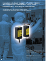
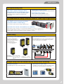
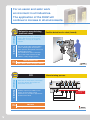
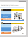
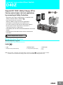
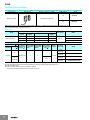
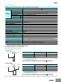
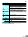
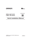
Compact Non-contact Door Switch
D40Z
Wide range of applications
at the highest safety level
Visible safety
»
Ultimate safety level
»
Versatile applications
Compliant with Safety Category 4/PLe (ISO 13849-1)
The compact non-contact feature allows easier
installation for a wide range of environments.
The D40Z can be used in work environments under any risk level.
Its combination with safety controllers allows for a wide range of applications.
D40Z
Safety Categories
Different types of machines will have different levels of associated risk. As an index
for determining the function to secure safety (safety function) based on the risk
evaluation, the ISO 13849-1 which stipulates safety-related parts of control
systems, categorizes the capability to maintain safety functions in the event of
control system failures as category B to 4.
Performance Level (PL)
An index of the safety control system performance level shared by a person who
implements risk assessment and a person who designs a machine is called
Performance Level (hereinafter abbreviated as "PL") and has 5 levels of evaluation
from "a" to "e".
For details on safety category and PL, refer to page 5.
1
D40Z Features
The highest safety level
ISO 13849-1 (Safety Category 4/PLe)
achieved with the non-contact door switch
The D40Z conforms to the international standard ISO 13849-1
(Safety Category 4/PLe) enabling use in hazardous work
environments.
r3FEVOEBOUJOUFSOBMDJSDVJU
The thorough pursuit of safety through mutual checking by double CPUs.
r4FMGEJBHOPTJTGVODUJPO
Made possible by adopting OMRON's original
safety-purpose electromagnetic induction method.
The combination with safety controllers allows for a wide range of applications.
The D40Z can be connected to Safety
Controller G9SP or G9SX-NS .
The controller can be selected according to application type.
Up to 30 units can be connected to one controller.
ntroller.
Up to 30 units can be connected to one controller while maintaining Safety Category 4 (ISO 13849-1).
Note: The G9SP supports 2 channels of 15 units each. For more information, refer to "Applicable level
and the number of connections according to controller combination" on page 5.
Visible safety
Checking at the production site
Centralized monitoring
The switch's LED indication
patterns make identification of
abnormal condition possible at
the production sites.
Note: For more information,
refer to page 10.
Bipolar NPN/PNP allows for easy connection with any PLC.
The error location can be easily identified. Using a branch
relay for a different pole is not required.
D40Z
PLC
Auxiliary output
Yellow LED ON
: Door closed (normal)
Yellow LED Blinking : When connected in series;
Other D40Zs are turned
OFF etc.
G9SX-NS
Red LED ON
: Door Open
Red LED Blinking : Error occurred
Compact body and non-contact feature allows easier mounting
Compact actuator
Mountable on both sides
The D40Z requires less space even inside the door.
The D40Z can be mounted to any door as the above feature
allows the user to select the direction to run the cable.
Can be
mounted
on both
sides.
48 mm
17 mm
Switch
25 mm
Small size
Actuator
Double door
r Switch: 48 mm x 25 mm
Slide door
rActuator: 48 mm x 17 mm
2
For an easier and safer work
environment in all industries.
The application of the D40Z will
continue to increase in all environments.
Automotive manufacturing
(multi-axis robot)
Problem
Detecting the position of a multi-axis
robot is difficult using a limit switch.
Additionally, it is easy to disable the
function.
Solution
The non-contact door switch enables
ease in detecting the robot position
which prevents the operator from easily
disabling the function.
The maintenance work is safer than
ever as the switch conforms to ISO
13849-1 (safety category 4/PLe).
Key
factor
Wide detection area
ISO 13849-1 (Safety Category 4/PLe)
FPD
There are too many doors, and it takes
too long to identify the location of a
failure when it occurs.
Solution
Auxiliary output is provided for each
switch. As each switch can be
monitored, it is possible to pinpoint the
location of the failure.
Key
factor
PNP/NPN
Up to 30 units connectable
D40Z
Manufacturing process
PLC
Up to 30 units can
be connected
G9SX-NS
Auxiliary outputs
Problem
3
Position detection of a robot (hazard)
D40Z
D40Z application examples
The D40Z solves problems at the production sites of various industries that require safety
(FPD, automotive parts, food, packaging, multi-axis robot, etc).
The D40Z supports a wide range of risk levels, contributing to a safer environment at
production sites for various industries' applications.
Food
Problem
The machine's small size limits the
space available to install a switch.
Solution
The D40Z's compact size fits into a
narrow space (Switch: 48x25 mm,
Actuator: 48x17 mm). The D40Z can
be used at an ambient operating
temperature of up to 65°C.
Key
factor
Compact size
Improvement on ambient operating temperature
Automotive parts
Problem
Although safety is ensured with a
contact door switch, particles are
generated which affect product quality.
Solution
With the non-contact door switch D40Z,
no particles will be generated through
friction.
Key
factor
Material processing
D40Z
Manufacturing process for secondary batteries
No particles generation
D40Z
4
Selectable controllers
A wide range of choices for the versatile applications
A combination of non-contact door switches and safety controllers can be selected according to
the application or the required risk level.
Mounting compatibility with the D40A allows for standardization of machine design.
Non-contact Door Switch
Safety
Category
/PL
Applicable level and the number of connections according to controller combination
Combination
Number of connectable
PL
D40Z Series
(maximum value)
+
D40Z
4
PLe
15 x 2
channels*
G9SX-NS
+
D40Z
4
PLe
30
G9SX-NSA
+
D40Z
4
PLe
30
G9SP
4/PLe
Category
D40Z
Combination
PL
Number of connectable
(maximum value)
D40Z Series
+
D40A
3
PLd
15 x 2
channels*
G9SX-NS
+
D40A
3
PLd
30
G9SX-NSA
+
D40A
3
PLd
30
G9SP
PL
Ld
3/PLd
Category
D40A
* G9SP-N10S supports 15 x 1 channel.
Safety Controller
G9SP
Non-contact Door Switch Controller
G9SX-NS
• Flexible programming
• Extensive system configurations
• Decreased work hours by convenient configurator
• Easy expansion of output points with an expansion unit
• Improved maintainability with LED display
• No special programming required
G9SP Series Catalog
Catalog No.: J181
5
D40A/G9SX-NS Catalog
Catalog No.: C140
Compact non-contact Door Switch
D40Z
Supports ISO 13849-1 (Safety Category 4/PLe).
Can be used on higher risk level applications
by connecting to Safety Controllers.
• Supports a wide range of applications in combination with
Safety Controller G9SP or G9SX-NS@.
• Up to 30 units can be connected.
Ideal for middle to large scale device applications.
• Contributes to shortening the time it takes to find
the cause of failure by the switch's LED display patterns.
• Photocoupler monitor output allows connection to
a general-purpose PLC (NPN type).
• Compatibility with the D40A allows standardization of machine
design.
• Compact Non-contact Door Switch can be mounted from
both sides.
Refer to “Safety Precautions” on page 14
Model Number Structure
Model Number Legend
Non-contact Door Switch (Switch/Actuator)
D40Z-@@@
–––
1 2 3
1 Type
1: Standard model (Switch/Actuator)
2 Auxiliary Output
C: 1 NO (Photocoupler Output)
3 Cable length
2: 2 m
5: 5 m
Note: Must be used in combination with a G9SP Safety Controller or G9SX-NS@ Non-contact Door Switch Controller.
For details, refer to G9SP Series Catalog (Cat.No.J181) or D40A/G9SX-NS Catalog (Cat.No.C140).
6
D40Z
Ordering Information
Non-contact Door Switch (Switch/Actuator)
Classification
Appearance
Auxiliary monitoring output
Cable length
Model
2m
D40Z-1C2
5m
D40Z-1C5
Photocoupler outputs *1
Standard models
Note: Must be used in combination with a G9SP Safety Controller or a G9SX-NS@ Non-contact Door Switch Controller.
*1. Photocoupler output. Load current: 10 mA
G9SP Series
No. of I/O points
Name
Safety
inputs
Safety Controller
Test
outputs
Standard
outputs
Safety outputs
10
4
Semiconductor outputs: 4
4
10
6
Semiconductor outputs: 16
--
20
6
Semiconductor outputs: 8
--
Unit version
Model
G9SP-N10S
Ver.1.0
G9SP-N10D
G9SP-N20S
Non-contact Door Switch Controller
Safety outputs *1
OFF-delayed
Instantaneous
*2
Auxiliary
monitoring
output *3
Logical AND Logical AND OFF-delayed
connection connection Max. OFF-delay
input
output
time *4
--
0
2
(Semiconductors)
2
(Semiconductors)
2
(Semiconductors)
Rated
voltage
1
1
24 VDC
3.0 s
Terminal
block type
Screw
terminals
G9SX-NS202-RT
Spring-cage
terminals
G9SX-NS202-RC
Screw
terminals
G9SX-NSA222-T03-RT
Spring-cage
terminals
G9SX-NSA222-T03-RC
*1. P channel MOS FET transistor output
*2. The OFF-delayed output becomes an instantaneous output by setting the OFF-delay time to 0 s.
*3. PNP transistor output
*4. The OFF-delay time can be set in 16 steps as follows:
0/0.2/0.3/0.4/0.5/0.6/0.7/0.8/0.9/1.0/1.2/1.4/1.8/2.0/2.5/3.0 s
7
Model
D40Z
Specifications
Ratings and Characteristics (Non-contact Door Switch)
Item
Model
Operating distance (OFF --> ON)
Operating
characteristics
D40Z-1C@
5 mm min. *1
Operating distance (ON --> OFF)
15 mm max. *1
Differential travel
Refer to “Detection Ranges (Typical Characteristics Data)” on page 9.
Influence of temperature
Refer to “Detection Ranges (Typical Characteristics Data)” on page 9.
Repeat accuracy
±10% of operating distance at 23 °C
Response time (ON --> OFF) *2
25 ms max.
Operating time (OFF --> ON) *2
100 ms max. (Distance between the switch and actuator is 5 mm)
Ambient operating temperature
-10 to 65 °C (with no icing or condensation)
Ambient operating humidity
25% to 85%
Insulation resistance (between charged parts and case) 50 MΩ max. (at 500 VDC)
Dielectric strength (between charged parts and case)
1,000 VAC for 1 min
Degree of contamination
3
Electromagnetic compatibility
IEC/EN 60497-5-3 compliant
Vibration resistance
10 to 55 to 10 Hz (single amplitude: 0.75 mm, double amplitude: 1.5 mm)
Shock resistance
300 m/s2 min.
Degree of protection
IP67
Material
PBT resin
Mounting method
M4 screws
Terminal screw tightening torque
1 N·m
Power supply voltage
24 V DC +10%/-15%
Power consumption *3
0.5 W max.
Auxiliary monitoring output
Photocoupler output: 24 V DC, load current: 10 mA
LED indicators
Actuator not detected (lights in red); error occurred (blinks in red), actuator detected (lights in
yellow), actuator detected and Non-contact Door Switch input OFF (blinks in yellow)
Connecting cables
2 m, 5 m
Number of connectable switches *4
30 max. (wiring length: 100 m max.)
Weight
Switch: approx. 175 g, actuator: approx. 20 g (D40Z-1C5)
*1. This is the distance where the switch operates from OFF to ON when approaching and the distance where the switch operates from ON to
OFF when separating when the switch and actuator target marks are on the same axis, and the sensing surface coincide. For details, refer to
“Detection Ranges (Typical Characteristics Data)” on page 9.
*2. Indicates the value of the non-contact door switch output.
*3. Power to be provided to the load is not included.
*4. For details, refer to item 17 on page 16.
Response Time and Operating Time
(1) G9SX-NS@
Max. response time
Max. operating time
(excluding Expansion Units) *1 (excluding Expansion Units) *2
Non-contact Door
Switch input
Logical AND input
Non-contact door switch input
Logical AND input
45 ms *3
200 ms *4
15 ms
100 ms
*1. The maximum response time is the time it takes the output to switch from ON to OFF after
the input switches from ON to OFF.
*2. The maximum operating time is the time it takes the output to switch from OFF to ON after
the input switches from OFF to ON.
*3. The value is the sum of D40Z's response time and G9SX-NS@'s response time.
*4. The value is the sum of D40Z's operating time and G9SX-NS@'s operating time.
(2) G9SX-NSA@
Non-contact Door
Switch input
Logical AND input
D4NS
Safety input
Max. response time
Max. operating time
(excluding Expansion Units) *1 (excluding Expansion Units) *2
Non-contact door switch input
45 ms *3
200 ms *4
Safety inputs
15 ms
50 ms
Logical AND input
15 ms
100 ms
*1. The maximum response time is the time it takes the output to switch from ON to OFF after
the input switches from ON to OFF.
*2. The maximum operating time is the time it takes the output to switch from OFF to ON after
the input switches from OFF to ON.
*3. The value is the sum of D40Z's response time and G9SX-NSA@'s response time.
*4. The value is the sum of D40Z's operating time and G9SX-NSA@'s operating time.
Note: The response time and operating time of the G9SP varies depending on the cycle time. For details, refer to the G9SP Series User's Manual (Cat.No.Z922).
8
D40Z
Engineering Data
16
16
14
14
12
Operating distance Y (mm)
Operating distance Y (mm)
Detection Ranges (Typical Characteristics Data)
OFF
10
8
ON
6
4
Side lobe
2
Side lobe
OFF
12
10
ON
8
6
4
2
0
0
–35 –30 –25 –20 –15 –10 –5
0
5
10
15 20
25
30
–30 –25 –20 –15 –10 –5
35
Distance from the target mark on the switch X (mm)
0
5
10
15 20
25
30
Distance from the target mark on the switch Z (mm)
14
Operating distance Y (mm)
OFF
X
12
Sensing surface
ON
10
8
6
Z*
4
Y
X=0, Z=0
2
0
–10°C
23°C
65°C
Target marks
* The movement of the arrow
direction indicates the positive
direction on the graph.
Effect of ambient temperature (°C)
Note: 1. The operating distance is the distance between the switch and actuator sensing surfaces.
2. Data in the diagram is typical data at an ambient temperature of 23. Actual operating values may vary. The operating distance may be
affected by ambient metal, magnet catches, and temperature.
3. Detection may occur other than on the detection surfaces of the switch and actuator. Before you use the switch and actuator, refer to
“Switch and Actuator Operation” on page 16 to set the detection surfaces of the switch and actuator face to face.
Connections
Internal Connection
D40Z-1C@
Internal circuit
Brown
Blue
White
Black
Yellow
Gray
9
D40Z
Troubleshooting
LED
indicator
Causes and corrective actions *1
Power supply input may be improperly wired. Check and correct wiring of brown and blue lines. Refer
to “Wiring of Inputs and Outputs” on page 11.
OFF
Fault in power supply
input (brown/blue)
Power supply voltage to D40Z may be insufficient.
Check the power supply voltage (between brown and blue lines) of D40Z fills ratings.
Refer to “Specifications” on page 8.
The wiring length or size of the wire may not be to the specification.
Check the wiring length and size of the wire. Refer to "Precautions for Correct Use".
Noise or
D40Z failure
Red
continuously
Fault in power supply
blinking
input (brown/blue)
Red blinks
once for 2s
Fault in Non-contact
door switch output
(black)
Red blinks Sensing fault
twice for 2s
Fault in Non-contact
Red blinks door switch input
thrice for 2s (white)
Yellow
blinking
There may be excessive noise. Check and correct ambient noise environment.
There may be a failure in internal circuit. Replace with a new D40Z.
Power supply voltage to D40Z may be insufficient.
Check the power supply voltage (between brown and blue cables) of D40Z fills ratings.
Refer to “Specifications” on page 8.
The wiring length or size of the wire may not be to the specification.
Check the wiring length and size of the wire. Refer to "Precautions for Correct Use".
Black line may be shorted to other line.
Check and correct wiring of black line if the black line is shorted to other lines. Refer to “Wiring of Inputs
and Outputs” on page 11.
Invalid actuator may be in a close range to switch.
Use the dedicated actuator.
Faulty signal may be input to white line.
Check and correct wiring of white line. Refer to “Wiring of Inputs and Outputs” on page 11.
OFF state of another
D40Z
Another D40Z may be in OFF state.
Check status of another D40Z connected to the white line and the wiring.
Refer to “Switch and Actuator Operation” on page 16 or “Wiring of Inputs and Outputs” on page 11.
Fault in Non-contact
door switch input
(white)
White line may be disconnected.
Check and correct wiring of white line. Refer to “Wiring of Inputs and Outputs” on page 11.
Red
Actuator fault
Solid-ON *2
Fault in Non-contact
door switch input
(white)
Yellow
Solid-ON *3 Fault in Non-contact
door switch output
(black)
There may be a failure in actuator. Replace with a new D40Z.
White line connected to D1 terminal (test output terminal of G9SP) of G9SX-NS@ may be shorted to
other line. Check and correct wiring of white line connected to D1 terminal (test output terminal of G9SP)
of G9SX-NS@ if the white line is shorted to other lines. Refer to “Wiring of Inputs and Outputs” on
page 11.
Black line connected to D2 terminal (safety input terminal of G9SP) of G9SX-NS@ may be
disconnected. Check and correct wiring of black line connected to D2 terminal (safety input terminal of
G9SP) of G9SX-NS@. Refer to “Wiring of Inputs and Outputs” on page 11.
*1.Another possible cause is a failure in internal circuit. In this case, replace with a new D40Z.
Yet another possible cause is excessive noise. In this case, check and correct ambient noise environment.
*2. The case where the guard door is closed (Switch detects actuator) is indicated.
*3. The case where the system stops though the guard door is closed (Switch detects actuator) is indicated.
10
D40Z
Dimensions/Wiring
(Unit: mm)
Non-contact Door Switch (Switch/Actuator)
D40Z-1C2
D40Z-1C5
Indicator
Cable diameter:
4.2 dia.
Target mark
Sensing surface
Sensing surface
Target mark
1.5
2
12 17
20 25
(7.2 dia.)
(7.2 dia.)
Two 4.2 dia.
Two 7.2 dia.
38
48
7
16
Two 7.2 dia.
38
48
(Actuator)
5.5
10.5
Two 4.2 dia.
16
(Switch)
Non-contact Door Switch and Non-contact Door Switch Controller or Safety Controller Wiring
Example of connection to G9SX-NS@ (Single connection)
Blue
Black
Brown
White
D40Z-1C@
D1 D2 D3 D4
G9SX-NS202
G9SX-NSA222
Example of connection to multiple switches
Example of auxiliary outputs
Connect up to 30 Non-contact Door Switches.
Yellow
24 VDC
COM
Blue
Brown
White
Black
Blue
Brown
White
Black
Blue
Brown
Black
White
PLC etc.
Gray
IN
Yellow
IN
PLC etc.
Gray
COM
24 VDC
Note: 1. The auxiliary output load current must be 10 mA max.
Wrong connection may lead to a failure of the auxiliary
output circuit.
2. For details on other wiring, refer to Application Examples
on page 12 or later.
D1 D2 D3 D4
G9SX-NS202
G9SX-NSA222
Wiring of Inputs and Outputs
Signal name
Non-contact Door Switch
power supply input
+
Brown
-
Blue
Description of operation
Supplies power to the D40Z.
Non-contact door switch input
White
To set non-contact door switch output in ON state,
non-contact door switch signal input must be in ON state.
Non-contact door switch output
Black
Output status depends on statuses of actuator and non-contact door switch signal input.
Yellow
Output status depends on status of actuator.
When a fault is detected, turns into OFF state regardless of actuator status.
Auxiliary monitoring output
11
Cable color
Gray
D40Z
Application Examples
G9SP-N20S(24 VDC) (2-channel Emergency Stop Switch Inputs + Non-contact Door Switch/Manual Reset)
G9SP-N20S
V1
Si0
Si1
Si2
Si3
Si4
G1
T0
T1
T2
T3
T4
Si5
V2
So1
So0
G2
DC24V
24 VDC
KM1
-NC
11
S1
S2
21
? 12
KM2
-NC
22
KM1
KM2
S3
Black
White
Brown
Blue
Yellow
Gray
24 VDC
GND
IN
COM
PLC etc.
KM1
GND
KM2
S1: Emergency Stop Switch
S2: Non-contact Door Switch (D40Z)
S3: Reset Switch
KM1, KM2: Contactor
M1: 3-phase motor
M1
Note: 1. The PL and category that correspond to this circuit example vary depending on the program configured to the G9SP-N20S.
For details, refer to "G9SP Series User's Manual (Cat.No.Z922)".
2. For details on terminal arrangement, refer to "G9SP Series User's Manual (Cat.No.Z922)".
3. Wire auxiliary outputs correctly. Incorrect wiring may lead to a failure of the auxiliary output circuit.
G9SX-NSA222-T03-@ (24 VDC) (2-channel Emergency Stop Switch Inputs + Non-contact Door Switch/Manual Reset)
Feedback Loop
KM1
S2
KM2
11
21
12
22
S2
Blue
Brown
Black
+24 V
White
S1
A1
T11 T12 T21 T22
Y1
Timing chart
NC NC
NC
T31 T32 T33
D1
D2
D3
D4
T41 T42
G9SX-NSA222-T03
AND
Control circuit
A2
S14 S24
ES1 ES2
L1
X1
Emergency stop
switch operation
OFF
Emergency stop switch S1
X2
D40Z
PLC etc.
24 VDC
KM1 KM2
S14
Motor controller
Reset switch S3
–
KM1, KM2 N.C. contact
KM1
GND
Motor controller
(Operation command)
S1: Emergency Stop Switch
S2: Non-contact Door Switch (D40Z)
S3: Reset Switch
KM1, KM2: Contactor
M1: 3-phase motor
KM1, KM2 N.O. contact
KM2
Operation command
Rotation of motor
M1
OFF-delay time
OFF-delay time
Note: 1. The example corresponds to category 4.
For details, refer to “Safety Category (EN 954-1, ISO 13849-1)” on page 16.
12
D40Z
G9SX-BC202 (24 VDC) (2-channel Emergency Stop Switch Inputs/Manual Reset) +
G9SX-NS202-@ (24 VDC) (Non-contact Door Switch/Auto Reset)
11
21
KM1 Feedback Loop
12
22
KM2
S1
S2
+24 V
NC
A1 T11 T12 T21 T22 T31 T32 T33 Y1
KM1
G9SX-BC202
KM2
+24 V
Control circuit
–
M1
A2
S14 S24
L1 L2
KM1 KM2
X1 X2
PLC etc.
Feedback Loop
S3
S1: Emergency Stop Switch
S2: Reset Switch
KM1, KM2: Contactor
M1: 3-phase motor
S3: Non-contact Door Switch (D40Z)
KM3, KM4: Contactor
M2: 3-phase motor
Timing chart
KM3
KM4
G9SX-BC202 (Upper unit)
A1
D1
D2
D3
Reset switch S2
Blue
Brown
Black
White
Emergency stop switch S1
+24 V
D4
T31 T32 T33
KM1, KM2 N.C. contact
T41 T42
G9SX-NS202
AND
Control circuit
KM1, KM2 N.O. contact
Logical AND output L1
OFF
Rotation of motor M1
A2
S14 S24
L1
X1
X2
G9SX-NS202-@(Lower unit)
PLC etc.
24 VDC
KM3 KM4
Logical AND input T41
KM3
–
D40Z
KM4
KM3, KM4 N.C. contact
KM3, KM4 N.O. contact
GND
M2
Rotation of motor M2
Note: 1. The example corresponds to category 4.
For details, refer to “Safety Category (EN 954-1, ISO 13849-1)” on page 16
13
Emergency stop
switch operation
D40Z
Safety Precautions
For details, refer to the "Precautions for All Switches" and "Precautions for All Safety Door Switches" on
"Best Component Catalog (Cat.No.Y106)".
For details on Safety Controllers, refer to G9SP Series Catalog (Cat.No.J181) or D40A/G9SX-NS Catalog
(Cat.No.C140).
WARNING
Serious injury may possibly occur due to breakdown
of safety outputs.
Do not connect loads beyond the rated value to the
safety outputs.
Serious injury may possibly occur due to loss of
required safety functions.
Wire the Edge Controller properly so that supply
voltages or voltages for loads do NOT touch the safety
outputs accidentally.
Serious injury may possibly occur due to breakdown
of safety outputs.
Apply protection circuitry against back electromotive
force in case connecting inductive loads to safety
outputs.
Serious injury may possibly occur due to loss of
required safety functions.
Use appropriate devices referring to the following
table.
The machine may start operating and may result in
serious injury or death. Do not put the actuator close
to the switch when the door is open.
Control device
Requirements
Emergency Stop
Switch
Use approved device with direct opening
mechanism complying with IEC/EN 60947-5-1.
Safety
Door Switch,
Safety
Limit Switch
Use approved device with direct opening
mechanism complying with IEC/EN 60947-5-1
and capable of switching micro loads of 24
VDC, 5 mA.
Non-contact
Door Switch
The G9SX-NS must be used with D40Z Noncontact Door Switches.
Relay with forcibly
guided contacts
Use approved devices with forcibly guided
contacts complying with EN 50205.
For feedback, use devices with contacts
capable of switching micro loads of 24 VDC,
5 mA.
Contactor
Use contactors with forcibly guided
mechanism to input the signal to the
Feedback/Reset input of the G9SX-NS
through the NC contact of the contactor.
For feedback, use devices with contacts
capable of switching micro loads of 24 VDC,
5 mA.
Failure to open contacts of a contactor cannot
be detected by connecting NC contact of the
contactor without a forcibly guided mechanism
to the Feedback/Reset input.
Other devices
Evaluate whether devices used are
appropriate to satisfy the requirements of the
safety category level.
Precautions for Safe Use
1. Disconnect the G9SX-NS from the power supply when wiring the
D40Z.Devices connected to the product may operate
unexpectedly.
2. Do not operate the product in atmospheres containing flammable
or explosive gas.
3. Wire conductors correctly and verify the operation of the product
before using the system in which the product is incorporated.
Incorrect wiring may lead to loss of safety functions.
4. Auxiliary monitoring outputs are NOT safety outputs. Do not use
auxiliary monitoring outputs as safety outputs. Such incorrect use
will cause loss of safety function of D40Z and peripheral devices.
5. After installing the D40Z, qualified personnel must confirm the
installation, and must conduct test operations and maintenance.
The qualified personnel must be qualified and authorized to secure
safety at each phases of design, installation, running,
maintenance, and disposal of the system.
6. A qualified person in charge, who is familiar with the machine in
which the D40Z is to be installed, must conduct and verify the
installation.
7. Be sure to inspect the D40Z daily and every 6 months. Otherwise,
serious injury may possibly occur due to system malfunctions.
8. Do not dismantle, repair, or modify the product. Doing so may lead
to loss of safety functions.
9. Do not apply DC voltages exceeding the rated voltages, nor any
AC voltages to D40Z.
10.Use a DC supply satisfying the requirements given below to
prevent electric shock.
- A DC power supply with double or reinforced insulation, for
example, according to IEC/EN 60950 or EN 50178, or a
transformer according to IEC/EN 61558.
- A DC supply satisfying the requirements for class 2 circuits or
limited voltage/current circuits stated in UL 508.
11.Connect the D40Z to only appropriate components or devices
complying with relevant safety standards corresponding to the
required level of safety category. Conformity to requirements of
the safety category must be determined for the entire system. It is
recommended to consult an authorized certification body
regarding assessment of conformity to the required safety level.
14
D40Z
Precautions for Correct Use
1. The D40Z must be used with a designated actuator and controller
to comply with EN ISO 13849-1.
2. Handle with care
Do not drop the product or expose it to excessive vibration or
mechanical shock. The product may be damaged and may not
function properly.
3. Storage and operating conditions
Do not store or use the products under the following conditions.
1.In direct sunlight
2.At ambient temperatures not between -10 and 65°C
3.At relative humidity not between 25% and 85%
4.In corrosive or combustible gases
5.Where subject to vibration or mechanical shock beyond the
rated values
6.Where subject to contact with oil or chemicals
7.In an atmosphere containing excessive dust, saline, or metal
powder
8.Where iron filings or powder may fall on the product
4. Do not use D40Z at altitudes over 1,000 meters.
5. Do not use to connect other switches or sensors to the wire
conductors of D40Z.
6. Disconnect D40Z and the controller connected to D40Z from
power supply when replacing D40Z. Failure to do so may cause
unexpected operation of devices connected to D40Z.
7. Keep D40Z from solvent such as alcohol, thinner, trichloroethane
or gasoline. Such solvents make the marking on D40Z illegible and
cause deterioration of parts.
8. Do not use D40Z in the magnetic field of 1.5 mT or more, otherwise
D40Z may not function properly.
9. Do not use D40Z in the water or continuous water exposure
environment, otherwise water may leak into D40Z. (An enclosure
of IP67 rating, which D40Z is rated, protects against temporary
immersion in water.)
10.Do not use D40Z switch or actuator as a stopper. Use a stopper to
protect the switch and the actuator. Keep a distance of at least 1
mm between the switch and the actuator.
11.Be sure to install D40Z switch and actuator in such as appropriate
distance that does not create a gap accessible to the hazard.
12.When installing two or more adjacent switches, keep a distance of
at least 50 mm from one another.
50 mm min.
13.Be sure that the machine is stopped whenever the guard door is
open.
14.Switch and actuator installed on a metallic material may affect the
operating distance. When installing them on a metallic material, be
sure to verify such an effect before using. Refer to the chart below
for the estimated effect.
Distance from
Operating distance
metallic materials
0 to 8 mm
Magnetic: Approximately 80% of the
original value
Aluminum: Approximately 90 to
110% of the original value
Larger than 8 mm
Not affected
15.Use M4 screws and washers to install the switch and actuator.
Tighten the screws with a specified torque. After installing and
commissioning, coat the switch-actuator fixing screws with
tamper-proof varnish or similar compound for locking. Using
anaerobic locking compounds can have a detrimental effect on the
plastic switch case if the compounds contact with the switch case.
Actuator
Switch
16.Wiring
1. Stranded wire : 0.2 to 2.5 mm AWG24 to AWG12
Solid wire
: 0.2 to 2.5 mm AWG24 to AWG12
2. When not using auxiliary output, cut off the unused
conductors and protect by insulating-taping to prevent
contacting with other terminals.
3. When you use an additional cable of 20 m or longer, use a
multiconductor cable to group the white, black, brown, and
blue lines together.
15
D40Z
17.Use cables of a total length of 100 m max. to connect multiple
D40Z switches. However, the total length of 200 m max. is
possible depending on the number of D40Z switches connected.
The supply voltage to D40Z may decrease by the voltage drop
depending on the cable or the wiring configuration. Check the
power-supply voltage is in the rated range.
30 or less D40Z connected
Switch and Actuator Operation
Switch and Actuator Mounting Directions
15 or less D40Z connected
Switch
Switch
Actuator
(Note 1)
Actuator
(Note 1)
Switch and actuator operating directions
Total wiring length 200 m max.
Total wiring length 100 m max.
Note 1
(Note 1)
D1 D2 D3 D4
(Note 2)
G9SX-NS202
G9SX-NSA222
D1 D2 D3 D4
(Note 2)
G9SX-NS202
G9SX-NSA222
Note 1.The wiring length between the products must be 100 m
max.
Note 2.For details on connection terminal and wiring of G9SP,
refer to the G9SP Manual (Cat.No.Z922).
18.D40Z is a class A product. In residential areas D40Z may cause
radio interference, in which case the user may be required to take
adequate measures to reduce interference.
19.D40Z may not function properly in surrounding environment with
strong electromagnetic equipment such as RFID system,
proximity sensor, motor, inverter, and switching power supply. If
you use D40Z near such equipment, be sure to verify effects of
such equipment on D40Z before using.
20.Handle cables with care:
1. For bending cables, it is recommended to bend them with a
radius of bend no less than six times the cable outer
diameter.
2. Do not apply a tensile strength of 50N or greater to the
cables.
21.To determine safety distance to hazards, take into account the
delay of non-contact door switch output caused the response time.
22.If there is any machine that has a large surge current (e.g., a
motor) near D40Z, connected a surge absorber to D40Z between
the blue and the other cables (white, black and brown)
respectively, or between the yellow cable and gray cable.
Suggested surge absorber's specification is as follows:
- Peak pulse power: 600 W (10/1000 μs) or more
(Per IEC 61000-4-5 (surge immunity))
- Breakdown voltage: 27-33 V
Note 1.When using the operating direction along the sensing
surface, be sure to install the switch and actuator so as
not to be affected by the side lobe.
Safety Category (EN 954-1, ISO 13849-1)
When used in combination with the G9SP or G9SX-NS@, the D40Z
can be used for the environments corresponding to performance level
e and safety category 4 as required by EN ISO 13849-1.
The settings are determined by circuit examples provided by
OMRON, however, and may not be applicable depending on the
operating conditions. Performance levels and safety categories are
determined for the safety control system as a whole. You must
confirm conformity for the entire system.
Approved Standards
D40Z-@/(used with G9SP or G9SP-NS@)
EN 954-1 Cat. 4
EN ISO 13849-1: 2008 Cat.4/PLe
IEC/EN 61508 SIL 3
EN 1088
IEC/EN 60497-5-3 PDF-M
IEC/EN 61000-6-4
UL 508
CAN/CSA C22.2 No.14
16
MEMO
17
READ AND UNDERSTAND THIS CATALOG
Please read and understand this catalog before purchasing the products. Please consult your OMRON representative if you have any questions
or comments.
Warranty and Limitations of Liability
WARRANTY
OMRON’s exclusive warranty is that the products are free from defects in materials and workmanship for a period of one year (or other period if
specified) from date of sale by OMRON.
OMRON MAKES NO WARRANTY OR REPRESENTATION, EXPRESS OR IMPLIED, REGARDING NON-INFRINGEMENT,
MERCHANTABILITY, OR FITNESS FOR PARTICULAR PURPOSE OF THE PRODUCTS. ANY BUYER OR USER ACKNOWLEDGES THAT
THE BUYER OR USER ALONE HAS DETERMINED THAT THE PRODUCTS WILL SUITABLY MEET THE REQUIREMENTS OF THEIR
INTENDED USE. OMRON DISCLAIMS ALL OTHER WARRANTIES, EXPRESS OR IMPLIED.
LIMITATIONS OF LIABILITY
OMRON SHALL NOT BE RESPONSIBLE FOR SPECIAL, INDIRECT, OR CONSEQUENTIAL DAMAGES, LOSS OF PROFITS OR
COMMERCIAL LOSS IN ANY WAY CONNECTED WITH THE PRODUCTS, WHETHER SUCH CLAIM IS BASED ON CONTRACT, WARRANTY,
NEGLIGENCE, OR STRICT LIABILITY.
In no event shall responsibility of OMRON for any act exceed the individual price of the product on which liability is asserted.
IN NO EVENT SHALL OMRON BE RESPONSIBLE FOR WARRANTY, REPAIR, OR OTHER CLAIMS REGARDING THE PRODUCTS UNLESS
OMRON’S ANALYSIS CONFIRMS THAT THE PRODUCTS WERE PROPERLY HANDLED, STORED, INSTALLED, AND MAINTAINED AND
NOT SUBJECT TO CONTAMINATION, ABUSE, MISUSE, OR INAPPROPRIATE MODIFICATION OR REPAIR.
Application Considerations
SUITABILITY FOR USE
OMRON shall not be responsible for conformity with any standards, codes, or regulations that apply to the combination of products in the
customer’s application or use of the product.
At the customer’s request, OMRON will provide applicable third party certification documents identifying ratings and limitations of use that apply
to the products. This information by itself is not sufficient for a complete determination of the suitability of the products in combination with the end
product, machine, system, or other application or use.
The following are some examples of applications for which particular attention must be given. This is not intended to be an exhaustive list of all
possible uses of the products, nor is it intended to imply that the uses listed may be suitable for the products:
• Outdoor use, uses involving potential chemical contamination or electrical interference, or conditions or uses not described in this document.
• Nuclear energy control systems, combustion systems, railroad systems, aviation systems, medical equipment, amusement machines, vehicles,
safety equipment, and installations subject to separate industry or government regulations.
• Systems, machines, and equipment that could present a risk to life or property.
Please know and observe all prohibitions of use applicable to the products.
NEVER USE THE PRODUCTS FOR AN APPLICATION INVOLVING SERIOUS RISK TO LIFE OR PROPERTY WITHOUT ENSURING THAT
THE SYSTEM AS A WHOLE HAS BEEN DESIGNED TO ADDRESS THE RISKS, AND THAT THE OMRON PRODUCT IS PROPERLY RATED
AND INSTALLED FOR THE INTENDED USE WITHIN THE OVERALL EQUIPMENT OR SYSTEM.
Disclaimers
CHANGE IN SPECIFICATIONS
Product specifications and accessories may be changed at any time based on improvements and other reasons.
It is our practice to change model numbers when published ratings or features are changed, or when significant construction changes are made.
However, some specifications of the product may be changed without any notice. When in doubt, special model numbers may be assigned to fix
or establish key specifications for your application on your request. Please consult with your OMRON representative at any time to confirm actual
specifications of purchased products.
DIMENSIONS AND WEIGHTS
Dimensions and weights are nominal and are not to be used for manufacturing purposes, even when tolerances are shown.
ERRORS AND OMISSIONS
The information in this document has been carefully checked and is believed to be accurate; however, no responsibility is assumed for clerical,
typographical, proofreading errors, or omissions.
PERFORMANCE DATA
Performance data given in this catalog is provided as a guide for the user in determining suitability and does not constitute a warranty. It may
represent the result of OMRON’s test conditions, and the users must correlate it to actual application requirements. Actual performance is subject
to the OMRON Warranty and Limitations of Liability.
PROGRAMMABLE PRODUCTS
OMRON shall not be responsible for the user’s programming of a programmable product, or any consequence thereof.
Copyright and Copy Permission
COPYRIGHT AND COPY PERMISSION
This document shall not be copied for sales or promotions without permission.
This document is protected by copyright and is intended solely for use in conjunction with the product. Please notify us before copying or
reproducing this document in any manner, for any other purpose. If copying or transmitting this document to another, please copy or transmit it in
its entirety.
OMRON Corporation
Industrial Automation Company
Authorized Distributor:
Tokyo, JAPAN
Contact: www.ia.omron.com
Regional Headquarters
OMRON EUROPE B.V.
Wegalaan 67-69-2132 JD Hoofddorp
The Netherlands
Tel: (31)2356-81-300/Fax: (31)2356-81-388
OMRON SCIENTIFIC TECHNOLOGIES INC.
6550 Dumbarton Circle, Fremont
CA 94555-3605 U.S.A.
Tel: (1) 510-608-3400/Fax: (1) 510-744-1442
OMRON ASIA PACIFIC PTE. LTD.
No. 438A Alexandra Road # 05-05/08 (Lobby 2),
Alexandra Technopark,
Singapore 119967
Tel: (65) 6835-3011/Fax: (65) 6835-2711
OMRON (CHINA) CO., LTD.
Room 2211, Bank of China Tower,
200 Yin Cheng Zhong Road,
PuDong New Area, Shanghai, 200120, China
Tel: (86) 21-5037-2222/Fax: (86) 21-5037-2200
© OMRON Corporation 2010 All Rights Reserved.
In the interest of product improvement,
specifications are subject to change without notice.
Printed in Japan
CSM_1_1_0910
Cat. No. C145-E1-01
0910