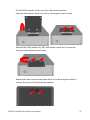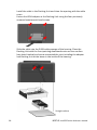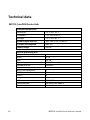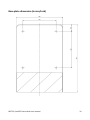
1
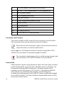
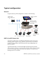
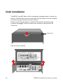
BEETLE /moPOS Device Hub User Manual We are interested in your opinion about this brochure. Please send us a message if you would like to provide constructive recommendations. For this, thank you in advance. Best regards, Your opinion: Wincor Nixdorf International GmbH Documentation R&D SAT11 Wohlrabedamm 31 D-13629 Berlin Email: [email protected] Order No.: 01750271257A BEETLE /moPOS Device Hub User Manual Edition June 2015 All other product names mentioned in this document may be the trademarks or registered trademarks of their respective owner. Copyright © Wincor Nixdorf International GmbH, 2015 All rights reserved, especially for translation, reprint, reproduction by copying or similar processes, (in whole or part).. Violations shall give rise to damages. All rights reserved, especially in the event of the awarding of a patent or utility model registration. Subject to availability and technical modifications. Contents Certification of the manufacturer .................................................. 1 Certified safety ................................................................................... 1 Important Notes ................................................................................ 1 Safety notes ....................................................................................... 2 Wireless LAN ..................................................................................... 4 Use of the device in a special environment ................................ 4 Introduction ................................................................................... 5 About this manual.............................................................................. 5 Recycling ............................................................................................ 6 Guarantee .......................................................................................... 6 Cleaning information ......................................................................... 7 Before switching on ....................................................................... 8 Unpacking and checking the scope of delivery .................................. 8 Installing the device ........................................................................... 9 Horizontal .................................................................................... 9 Vertical ...................................................................................... 10 Cabling of the BEETLE /moPOS Device Hub .................................. 11 Basic settings ................................................................................... 12 BEETLE /moPOS Device Hub ......................................................... 13 Exterior ............................................................................................ 13 Interfaces ......................................................................................... 13 Cash drawer (RJ12 socket) ........................................................ 14 PoweredUSB.............................................................................. 14 DC in (power plug) .................................................................... 15 PS/2 (Mini-DIN, keyboard) ........................................................ 15 LAN (RJ45) ................................................................................. 15 COM2*supplied with power (D-Sub socket) ............................. 16 COM1 (D- Sub plug)................................................................... 16 DP (Display Port, monitor connection) ..................................... 16 DVI-I........................................................................................... 16 USB (Universal Serial Bus) A 2.0 ................................................ 16 Audio (3.5 mm stereo jack bushes) ........................................... 17 Typical configuration .................................................................... 18 Network ........................................................................................... 18 BEETLE /moPOS Device Hub ............................................................ 18 BEETLE /moPOS tablet ..................................................................... 19 BEETLE /moPOS Docking Unit .......................................................... 19 Desk installation........................................................................... 20 Wall mounting ............................................................................. 23 Technical data .............................................................................. 30 BEETLE /moPOS Device Hub ............................................................ 30 Base plate dimension (in mm/inch) ................................................. 31 BEETLE /moPOS dimension (in mm) ................................................ 32 Total current consumption interfaces ............................................. 34 Abbreviations ............................................................................... 35 Certification of the manufacturer This device fulfils the requirements of the EU Directive 2004/108/EC “Electromagnetic Compatibility” and 2006/95/EC "Low Voltage" Directive as well as RoHS 2011/65/EU. For this, it bears the CE label on the rear side or the symbol is printed on the packaging. Certified safety Your device is UL and cUL certified. Important Notes The BEETLE /moPOS Device Hub is in accordance with the relevant safety regulations for data processing equipment. Repairs to the device may only be performed by authorized specialized personnel. Improper repairs will lead to the loss of any liability claims. Expansion boards with electrostatic-discharge-sensitive components (EGB) may be labeled with this sticker. If you open the device or if you handle assemblies with EGB, please adhere to the following: Before you are working with such assemblies, you should discharge yourself by touching a grounded object. Devices and tools put to use must be free from static charge. Unplug the power plug before you plug-in, unplug or install the EGB. Only touch the EGB at the edge. BEETLE /moPOS Device Hub user manual 1 Do not touch any connector pins or conductive paths on an EGB. Wincor Nixdorf International GmbH is not responsible for radio and TV emissions, which are created by unauthorized changes to the devices. In addition, cable or devices that are not authorized by Wincor Nixdorf must not be connected. The user is responsible for disturbances that are created by the above. Safety notes Condensation may occur if this device is brought to the working area from a cold environment. The device must be absolutely dry before commissioning, therefore an acclimatization period of at least two hours must be observed The external power supply is equipped with a safety tested mains cable. It must only be connected to a properly grounded protective contact electrical outlet. When installing the devise, please ensure that the devise plug-in fixture or the protective contact electrical outlet is easily accessible. The device must be fully disconnected from the mains power when performing any work at the device and if inserting or removing data cables. In order to completely separate the appliance from the mains voltage, switch off the device and unplug the power plug of the power supply. USB devices may be connected to the BEETLE system or removed from the BEETLE system during ongoing operations if these devices comply with the specifications pursuant to usb.org. Other peripherals (e.g. PoweredUSB printer) should – for safety reasons – only be connected to or disconnected from switched off BEETLE systems. Before you begin any assembly work on the device, you should discharge yourself by touching a grounded object (e.g. a radiator). Please make sure that no objects (e.g. paperclips) are able to enter the inside of the device, as this may result in electrical shocks or short circuiting. During storms no data cables may be plugged in or unplugged. Protect the device from vibrations, dust, moisture and heat. 2 BEETLE /moPOS Device Hub user manual Please guarantee the environmentally friendly disposal of used parts, for example the battery. In the event of emergencies (e.g. damaged housing or damaged power cable, penetration of liquids or foreign bodies), please switch the device immediately off, pull the power plug and inform the technical customer service of Wincor Nixdorf International GmbH or the authorized service partner of your dealer. An explosion hazard exists if the lithium battery of the device is incorrectly exchanged. The lithium battery must only be replaced by identical batteries or by types recommended by the manufacturer. Your BEETLE system is the result state of the art innovation. Please ensure therefore state of the art constructional and technical ambient conditions to permit a flawless and efficient functioning of the BEETLE system. You should only connect the BEETLE system or any other IT system to power supply networks with separate protective conductors (PE). This type of power supply network is called TN-S network. Do not use PEN conductors! Please also observe the recommendations of DIN VDE 0100 part 540, Annex C2. This will help you avoid any potential function disturbances. When exchanging a storage medium, please ensure that you only use storage media authorized or recommended by Wincor Nixdorf. BEETLE /moPOS Device Hub user manual 3 Wireless LAN Make sure to observe the following safety notes: Use of the device in a special environment Wireless devices must only be used in a restricted capacity in explosion hazard areas. The restrictions will be defined by the responsible bodies in these operations. Please adhere to the following warning when operating the BEETLE system. Warning Wireless network devices must not be operated in the proximity of detonators that are not shielded or in an explosion hazard environment. Except if the device was modified and adapted for this use. 4 BEETLE /moPOS Device Hub user manual Introduction BEETLE /moPOS is an innovative, modular and scalable hardware and Middleware solution. It consist of several modules that are designed for the typical mobile applications in state of the art retail stores. Normally, the BEETLE /moPOS consist of a tablet, a BEETLE /moPOS Device Hub and a BEETLE /moPOS Docking Unit. One module of the mobile POS solution is the BEETLE /moPOS Device Hub. The stationary POS Device Hub offers a state of the art design in a stainless steel look. It provides the required traditional peripheral interfaces and is used as the service point, which can be used by several tablets for a checkout process. Independent of the configuration that you need, Wincor Nixdorf international GmbH can offer the right solution. In case of questions about your BEETLE /moPOS or other products and solutions of Wincor Nixdorf, please visit us on the Internet: http://www.wincornixdorf.com/internet/site_DE/DE/Home/homepage_node.html About this manual The objective of this document is to aid you in the use of the system and also serve as a reference guide. The detailed table of contents make it easier for you to find the information you need. Notifications are marked in the manual by this sign. Attention notifications are identified by this sign. As the type and scope of the application programs depend on the individual specific choice of each customer, this manual will not deal with any detailed issues pertaining to software. BEETLE /moPOS Device Hub user manual 5 Dedicated manuals are available for the peripherals that can be connected. Therefore, these devices will not be described in detail here. Please inform yourself by studying the respective manuals. http://www.wincornixdorf.com/internet/site_DE/DE/Support/Downloads/POSLotterySystems /Manuals/manuals_node.html Recycling Environmental protection does not only start during the disposal of systems, but already during their production. This product was designed in accordance with our internal standard "Environmentally friendly product design and development". The BEETLE /moPOS Device Hub is manufactured without the use of FCKW and CKW and it is mainly produced based on components and materials, which can be recycled. You are helping us for the recycling if you do not attach any labels to the device. For materials, which currently cannot be used for a new purpose, Wincor Nixdorf International offers the environmentally friendly disposal in a recycle center, which is certified in accordance with ISO 9001 and ISO 14001. If your BEETLE /moPOS system can no longer be used, please send it to this environmentally friendly and contemporary form of recycling. Additional information about returns, recycling and disposal of our products can be obtained from your responsible branch office or from our recycle center in Paderborn. Email: [email protected] We look forward to your email. Guarantee In general, Wincor Nixdorf (WN) guarantees a warranty of 12 months after delivery or acceptance date. This warranty covers all defects that occurred during normal use of the product. 6 BEETLE /moPOS Device Hub user manual Defects based on incorrect or inadequate maintenance, incorrect use or authorized changes at the product, and unsuitable location or an unsuitable environment are not covered. All wear parts are also not covered by warranty. More details about the warranty regulation can be found in your contract documents. If a claim for warranty of the product does not exist and if you do not have a service contract with Wincor Nixdorf, then the Wincor Nixdorf Customer Care Center (CCC) is available for an order acceptance without a contract. Phone: 0180 1 WINCOR (Vanity Number, subject to charge) Phone: 0180 1 1 99 2 99 (subject to a charge) Email: mailto:[email protected] Cleaning information Clean the system parts frequently with a lint-free cloth. For greater amounts of soiling, please use a cleaning agent suitable for plastic surfaces, which you can order from Wincor. Nixdorf International. Make sure that the device is deactivated during cleaning, that the power plug is disconnected and that no moisture enters the inside of the device. BEETLE /moPOS Device Hub user manual 7 Before switching on Unpacking and checking the scope of delivery Unpack the parts and check whether they correspond to the parts listed on the bill of delivery. The carton contains the BEETLE /moPOS Device Hub and a country-specific accessory kit. Should you detect any transport damages or inconsistencies between package content and the bill of delivery, please inform your contractual partner or sales outlet of Wincor Nixdorf International GmbH. For this purpose, please provide the bill of delivery, the bill of delivery item and the serial number of the device. The serial number can be found on the underside of the system. Serial number We recommended keeping the original packaging for any subsequent transporting (protection against jolts and impact). 8 BEETLE /moPOS Device Hub user manual Installing the device Install the BEETLE /moPOS Device Hub in such a way that the system is not subjected to extreme ambient conditions. Protect the device against vibrations, dust, moisture, heat and strong magnetic fields. Horizontal Please adhere to the listed minimum distances adjacent and behind the device! If you want to incorporate the device, it is mandatory that you adhere to the minimum distances listed below and ensure a constant aeration and ventilation. The direct ambient temperature of the system must not exceed 35°C. . Distances for ventilation BEETLE /moPOS Device Hub user manual 9 Vertical To guarantee a correct ventilation even for a vertical installation, adherence to the following is required with free convection (see above figure). The illustration shows the BEETLE /moPOS Device Hub with a Docking Unit. 10 BEETLE /moPOS Device Hub user manual Cabling of the BEETLE /moPOS Device Hub All devices that are part of the BEETLE /moPOS Device Hub and that have their own dedicated mains voltage cable must be connected to the same circuit. Please ensure that all data cables are plucked at the POS Device Hub and that the peripherals are plugged in. Plug the power cable into the socket on the rear of the Device Hub. Plug the power cable into the socket of the external power supply and plug the other end into the protective contact electrical outlet of the house installation. The device switches on automatically, which means that the device starts while the on/off switch must not be actuated. 1 2 On/off switch at the front Power supply (DC in) at the rear BEETLE /moPOS Device Hub user manual 11 Switching off during the operation is possible, for this purpose, press the button for app. 10 seconds. To switch the device on, briefly switch the on/off button at the front. Do not plug in data or power supply cables if the system is plugged in! Basic settings The BEETLE /moPOS Device Hub is configured in accordance with your order when it leaves the factory. Additional devices such as scanners must be adapted to your configuration afterwards. For this purpose, contact the responsible WN branch office. 12 BEETLE /moPOS Device Hub user manual BEETLE /moPOS Device Hub Exterior Cable cover Housing LEDs: HDD (top), Power Base plate ON/OFF switch Connection point Docking Unit Interfaces ② ⑦ ③ ⑧ BEETLE /moPOS Device Hub user manual ⑨ ④ ⑤ ⑥ ⑩ 13 1 CD (Cash Drawer), cash drawer (RJ12 socket) 2 1 x 12V*, 2 x 12V PoweredUSB, 1 x 24V PoweredUSB 3 DC in (power supply) 4 PS/2, keyboard (Mini DIN) 5 LAN (RJ45 socket) 6 COM2*supplied with power (D-Sub) 7 COM1 (D-Sub) 8 DP (DisplayPort) 9 DVI-I 10 4 x USB-A (USB 2.0) 11 In, Out, Mic (3 x 3.5 mm jack bush) Cash drawer (RJ12 socket) The system includes an RJ12 socket for the connection of a cash drawer. This connection must only be used to connect a till drawer. Please ensure that the plug has a tight contact with the socket because otherwise it can lead to malfunctions. Once plugged in, RJ12 plugs are locked. The power supply (P24V +5% / 15%) for the cash drawer is provided through this socket. The connection of sub-drawers (the so-called looping through) and the connection of 12 V OEM till drawers is not permitted! PoweredUSB USB peripherals, whose energy demand is higher than the supply provided by the standard USBs, such as printers, barcode scanners or displays, can be operated at PoweredUSB connections. The power supply is 24 V (marked in red for POS printers, 12 V and 12 V*. The powered USB12V* (hub) interface is provided for the operation of the Docking Unit. A mechanical coding prevents that a USB 12 V plug is accidentally plugged into a USB 24 V socket. The lower half of the PoweredUSB socket can also be used as a USB-A socket. 14 BEETLE /moPOS Device Hub user manual DC in (power plug) The power supply is provided through this socket. Please plug the appropriate end of the power cable into this socket and into the socket of the external power supply. To disconnect the device from electrical power, unplug this plug. PS/2 (Mini-DIN, keyboard) The BEETLE /moPOS Device Hub includes a 6 pin mini DIN socket for the connection of a keyboard. Please ensure that the plug has a tight contact with the socket because otherwise it can lead to malfunctions. The power supply for the keyboard is provided through this socket. A special adapter cable is required for the connection of a PC standard keyboard with a PS/2 plug. If required, contact your responsible Wincor Nixdorf branch office. It is possible to additionally connect PS/2 mouse to the keyboard by using a Y adapter. LAN (RJ45) The cable for the connection to a network (LAN) will be plugged in here. LEDs Left LED Right LED Constant green Network connection established Flashes green Data transfer Off 10 MBit Constant green 100 MBit Constant orange 1000 MBit Only use shielded LAN cables with the markings CAT5, CAT5e (for 1000 MBit) or better. They provide a higher protection against disturbances in the network. BEETLE /moPOS Device Hub user manual 15 COM2*supplied with power (D-Sub socket) Scanner, customer or operator displays without their dedicated power supply will be connected to this interface independent of the existing configuration. A 9 pin D sub-socket is used for this purpose. Please ensure, that the plug of the peripherals is tightly screw connected with the socket because otherwise it can lead to malfunctions. The power supply is provided through this socket. COM1 (D- Sub plug) The COM1 interface can be used, for example, to connect a scale with its own power supply. COM1 is designed as 9 pin D sub-plug. If you connect scales to the BEETLE /moPOS Device Hub, which are not delivered by WN, then you must acquire a WN license for the driver software! Please ensure that the plug is tightly screw connected with the socket because otherwise it can lead to malfunctions. DP (Display Port, monitor connection) The Display Port is a universal, standardized connection for display devices (displays, beamers) for the transmission of image data. It has a resolution of up to 2560 x 1600 pixels and a refresh rate of 60 images per seconds for a high image quality. The plug is smaller than a DVI connection. Therefore it is the optimal solution if only limited space is available. DVI-I The DVI interface is used for the connection of a high-resolution monitor to the BEETLE system. This is where video signals with a maximum resolution of 1920 x 1200 pixels can be transmitted at 60 Hz. USB (Universal Serial Bus) A 2.0 Several USB peripherals can be connected to these connections (USB-A), e.g. scanners, scales or dongles or graphic cards or monitors. USB can provide the required power for devices with little wattage such as phones or keyboards. 16 BEETLE /moPOS Device Hub user manual Only devices and cables that are in accordance with the valid USB specifications can be connected to the USB interfaces. Audio (3.5 mm stereo jack bushes) Audio devices such as headphones, loudspeakers and microphones can be connected to these connectors. The three sockets are mechanically identical, however, they are different with respect to their function. The light blue socket (line in) is an audio input. This is where external audio sources can be connected. The green socket (line out) is an audio output. This is where headphones or loudspeakers can be connected. And finally, a microphone can be connected to the pink colored socket (Mic). You can adjust the required volume through the software in the operating system or through the operating system itself (for example, the operating system offers a small loudspeaker symbol on the taskbar, which can be used to control the volume). BEETLE /moPOS Device Hub user manual 17 Typical configuration Network A typical stationary POS configuration is shown in the following: WLAN router Branch office netk BEETLE /moPOS tablet BEETLE /moPOS Docking Unit and Device hub Customer disl EFT POS printer BCR cash drawer Customer/user display BEETLE /moPOS Device Hub The typical configuration of a BEETLE /moPOS Device Hub is the one as BEETLE /moPOS. Together with a BEETLE /moPOS Tablet and a BEETLE /moPOS Docking Station, the POS device hub is the configuration of a BEETLE /moPOS. The POS Device Hub is connected through the Ethernet to the branch office network, however, it communicates with the tablets always through wireless technology independent of the fact whether it is locked into a Docking Unit or if it is mobile. 18 BEETLE /moPOS Device Hub user manual BEETLE /moPOS tablet The BEETLE /moPOS Tablet is a component of the BEETLE /moPOS. It is signified by its robustness and a state of the art design. The industry tablets with dimensions of 8.3 inches and 10.1 inches based on Intel's Embedded Processor Technology Bay Trail-T come preinstalled with the Microsoft operating system Windows 8.1. This offers the benefit that Windows applications can be run and that new developments are not required. In addition, retail companies can expand their software suites with state of the art apps. As an alternative, tablets can in the future also be operated on an Android platform, which means that traditional Fat Clients and Cloud or serverbased solution architectures can be supported for POS systems. Additional information about the BEETLE /moPOS tablet can be found in the respective manual. BEETLE /moPOS Docking Unit A lockable Docking Unit provides a safe latching of the tablet during the checkout process and protects the tablet against theft. The unlocking is motor driven and is controlled by the application. In an emergency case, unlocking can also take place using a key. The presence of the tablets as well as the device ID will be checked through sensors. In addition, the Docking Unit also charges the battery of the tablet while it is locked. Additional information about the BEETLE /moPOS Docking Unit can be found in the respective manual. BEETLE /moPOS Device Hub user manual 19 Desk installation The BEETLE /moPOS Device Hub is completely equipped when it leaves the factory. To fasten the system on the table, the base plate must be removed from the housing. Please proceed as follows: Please ensure that the device is switched off and that the power plug has been unplugged. Slide the cable cover forward in the direction of the arrow. Cable cover Flap the cover upwards. 20 BEETLE /moPOS Device Hub user manual Rotate the screw at the rear in the direction of the arrow to separate the base plate from the housing. Pull the BEETLE /moPOS Device Hub forward and remove it upwards. Place the BEETLE /moPOS Device Hub at the side. BEETLE /moPOS Device Hub user manual 21 Use the base plate as a template and draw the installation points on the desk (detailed information about the dimensions can be found in the section "Technical data"). Fasten the base plate on the table. Use suitable flathead screws (max. 1.1 mm head height) or countersunk head screws (thread diameter max. 4 mm). Reassemble the BEETLE /moPOS Device Hub in reverse order. 22 BEETLE /moPOS Device Hub user manual Wall mounting If the BEETLE /moPOS Device Hub is equipped with a Docking Unit in accordance with your configuration ex works, then this configuration is by default provided as a desk version. A modification to wall mounting is possible. Please proceed as follows: Please ensure that the device is switched off and that the power plug has been unplugged. Unplug all cables that are plugged into the Device Hub. Slide the cable cover to the rear in the direction of the arrow. Cable cover BEETLE /moPOS Device Hub user manual 23 Flap the cover upwards. Rotate the screw at the rear in the direction of the arrow to separate the base plate from the housing. Pull the BEETLE /moPOS Device Hub forward and remove it upwards. 24 BEETLE /moPOS Device Hub user manual Use the base plate as a template and draw the installation points on the wall (detailed information about the dimensions can be found in the section "Technical data"). Loosen the screw above the 24 V DC socket. Remove the PC box from the BEETLE /moPOS Device Hub housing and place it at the side. Remove the cable feed through bezel at the front of the Device Hub. PoweredUSB cable BEETLE /moPOS Device Hub user manual 25 Pull the PoweredUSB cable carefully out of the housing. Slide the rear right cable cover to the outside and remove it. Place the cover at the side and install the cables to the rear. Bring the Docking Unit into a vertical position. Remove the 4 countersunk head screw on the rear of the Docking Unit. 26 BEETLE /moPOS Device Hub user manual Tilt the VESA adapter to the rear into a horizontal position. Separate the adapter from the joint by removing the two screws. Rotated the VESA adapter by 180° and fasten it with the 2 previously removed countersunk head screws. Remove the two screws at the beam with in the housing to be able to remove the joint with the fastened adapter. BEETLE /moPOS Device Hub user manual 27 Install the cable in the Docking Unit and close the opening with the cable cover. Fasten the VESA adapter at the Docking Unit using the four previously removed countersunk head screws. Slide the cable into the PUSB cable passage of the housing. Place the Docking Unit with the front pointing downwards onto an even surface (see sketch below) and screw connected the joint including the adapter and Docking Unit at the beam in the inside of the housing. Straight surface 28 BEETLE /moPOS Device Hub user manual Route the PUSB cable at the side around the joint and pull the cable into the PDH housing in such a way that it is tight around the joint. Insert the cable throughput bezel. Install the PUSB cable within the housing in the cable bracket. Install the PC box in the housing and fixate the PC box at the housing with the fastening screw. Hang the devise into the bracket mounted on the wall. Fixate the device at the bracket with the knurled-head screw underneath the cable cover. Pug in the required interface cables in accordance with the planned installation at the devise and close the cable cover. BEETLE /moPOS Device Hub user manual 29 Technical data BEETLE /moPOS Device Hub Ambient temperature Operation Transport Storage Power supply ADC029 Current consumption Input voltage Central processing unit Processor RAM SSD Operating system Software driver Interfaces RS232 non-powered RS232 powered USB-A PoweredUSB 12V/24V Video LAN Ethernet Cash drawer 30 + 5 °C to + 35 °C - 25 °C to + 60 °C + 5 °C to + 40 °C 100- 240 V, 2A, 50-60 Hz max. 5A 24V DC Atom D2560 2 GB 16 GB WNLPOS Live System JavaPOS 1 1 4 3 /1 DVI-I/ DP 10/100/1000 Mbit/s 1 BEETLE /moPOS Device Hub user manual Base plate dimension (in mm/inch) BEETLE /moPOS Device Hub user manual 31 BEETLE /moPOS dimension (in mm) Displayed here in its desk version with an optionally available tablet. Angle adjustment of the tablet (10”/8”): 60° 60° 301/ 274 185 68.5 295 190 270/ 228 308 32 BEETLE /moPOS Device Hub user manual Displayed here in its wall version with an optionally available tablet. (10”/8”). 270/228 440/ 410 BEETLE /moPOS Device Hub user manual 33 Total current consumption interfaces The total current consumption of 5 V interfaces must not exceed 2 A: überschreiten: Com* Each USB2.0 Each USB (HUB) = 300 mA (5 V) = 500 mA, total 2A = 500 mA, total 2A The total current consumption on 12 V interfaces must not exceed 2 A: überschreiten: Com* Each USB (HUB) = 600 mA = 1.5A, total 2A Current across all ports Voltage Current per port 22..24V - 12V 1A (max. 250ms) qualified to charge the tablet 12V powered USB 12V 1.5A 2A 1 x 24V PoweredUSB PS/2, keyboard (Mini DIN) LAN (RJ45 socket) COM2* supplied with power (D-Sub) COM1 (D-Sub) 24V 2.3A - 5V - - - - - 5V/12V 0.3A/0.6A 0.5A/0.9A RJ12 socket/cash drawer 1 x 12V*, - - - - DP (DisplayPort) - - - DVI-I - - - 5V 0.5A 2A - - - USB-A (USB 2.0) In, Out, Mic (3 x 3.5 mm jack bush) The powered USB12V* (hub) interface is provided for the operation of the Docking Unit. The 24 V PoweredUSB interface is provided for the operation of retail thermal printers authorized by Wincor Nixdorf. 34 BEETLE /moPOS Device Hub user manual Abbreviations Abbreviations Descriptions A Ampere BCR Barcode Reader or Scanner CE COM COM* cUL European conformity symbol RS 232 interface RS 232 interface (star = power supply) Canadian Underwriters Laboratories DIN Standards) D-Sub DVI-I Deutsches Institut für Normung (German Institute for D- Shaped Subminiature Digital Visual Interface Integrated (analog and digital) EFT EG EGB EU Electronic funds transfer European Community Electrostatic sensitive module elements European Union ID ISO Industrial Design International Organization for Standardization LAN LED Local Area Network Light Emitting Diode PEN-Leiter POS Protective Earth Neutral conductor Point Of Sales RAM RJ Random-Access Memory Registered Jack e.g. RJ45 SSD Solid State Drive BEETLE /moPOS Device Hub user manual 35 36 TN-S Terre Neutre- Separé UL USB Underwriters Laboratory (standards) Universal Serial Bus V VDE VESA Volt Association of Electrical Engineering, Electronics and Information Technology e.V. Video Equipment Standards Association W WLAN WN Watt Wireless Local Area Network Wincor Nixdorf International GmbH BEETLE /moPOS Device Hub user manual Wincor Nixdorf International GmbH D-33094 Paderborn Order No. / Bestell-Nr.: 01750271257A