1
=rom
tie
Pub ishers of
sonRadio- Electro-iics
ROW
-6 TIMES A YEAR
Electron
TI-E MAGAZINE
THE ELEC'RONICS ACTIVIST!
NEW: DataCard
Teerout file -card information
Start your collection tray!
Give the unknown DIP a name!
DIGITAL
CRIBBAGE
BOARD
century card game
that's gone digital!
A 17th
Discover what and how
impor :ant it is for
getting the sigral out
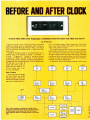
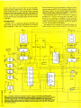
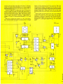
Before & After Clock
Displays time the way
you say t!
7
.
GERMSBACF".
LA -,N
43784
$2 50 U.S.
$2.95 CANADA.
JANUARY. FEBRUARY
19E6
6
One -Evening
PROJECTS
Anyone Can
Build
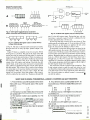
TEK
THE ANSWER
BY ANY MEASURE
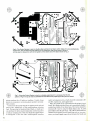
DUAL TRACE OSCILLOSCOPES
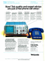
Now! Tek quality and expert advice
are just a free phone call away!
The industry
standard in CRT
performance.
Crisp, easy -toread, bright CRT;
14kV accelerating
potential, provides
high writing rate
and small spot
size. Full size 8x10
cm display for
measurement
accuracy.
Display controls
are flexible and
easy to use. Separate intensity
controls reduce
blooming in alternate sweep mode.
Focus tracking
minimizes control
adjustment and
BEAM FIND eliminates confusion.
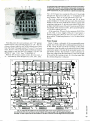
Our direct order line gets
you the industry's leading
price/performance portables...
and fast answers from experts!
The 60 MHz single time base delay
2213A, the 60 MHz dual time base
2215A and the 100 MHz dual time
base 2235 offer unprecedented
reliability and affordability, plus the
industry's first 3 -year warranty*
on labor and parts, CRT included.
The cost: just $1275 for the
2213A, $1525 for the 2215A,
$1750 for the 2235.t Even at
these low prices, there's no
scrimping on performance. You
Vertical system provides
measurement
assurance. Flat
transient response
and high accuracy
Perform delayed
sweep measurements accurately
and easily. Both
sweeps can be
displayed alter-
ensures true
reproduction of
your signals. Fast
risetime and high
bandwidth is well
suited for a variety
of measurement.
nately making differential measurements easy and
accurate (1 %).
An interlocking
SEC /DIV control
simplifies set -up
have the bandwidth for digital
and analog circuits. The sensitivity
for low signal measurements. The
sweep speeds for fast logic families. And delayed sweep for fast,
accurate timing measurements.
All scopes are UL Listed and CSA
approved.
You can order, or obtain
literature, through the Tek
National Marketing Center. Technical personnel, expert in scope
applications, will answer your
questions and expedite delivery.
Direct orders include comprehensive 3 -year warranty *, operator's
Stable hands -off
triggering.
P -P
AUTO detects signal peaks, then
sets the trigger
level for you. Display asynchronous
signals using
VERT MODE trig-
gering. Independent TV field and
line selection.
Front panel laid
out by function
for ease of use.
Color coding aids
the user in operation. Functions
and modes are
placed logically.
All nomenclature
is clearly labeled,
and protected
behind a scratch less Lexan surface.
manual, two 10X probes, 15-day
return policy and worldwide service backup.
Order toll free:
1- 800 -426 -2200,
Ask for Rick.
Oregon, call collect:
(503) 627 -9000.
Or write Tektronix, Inc.
P.O. Box 1700
Beaverton, OR 97075
In
TéJctronbco
COMMITTED TO EXCELLENCE
Copyright m 1985, Tektronix, Inc. All rights reserved. #TTA- 439 -3. tPrice F.O.B. Beaverton. OR. '3 -year warranty includes CRT.
CIRCLE 718 ON FREE INFORMATION CARD
Volume 3, No.
January /February 1986
1
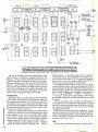
SPECIAL PROJECT-BUILDERS
16 -PAGE SECTION
Budget Project Parade
Budget projects parade-page 53
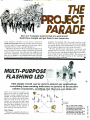
53 Multi- purpose Flashing LED
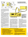
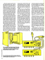
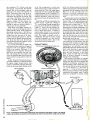
56 Electronic Dice
59 A Simple Amplifier
62 Home and Car Alarm
65 Integrated Shortwave Receiver
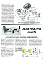
67 Electronic Siren
FEATURES
Identifying Unknown IC's-let the chip's "signature" detect
its
Digital cribbage board -page 23
function and type
SWR -what it means in practice
Assemble
a
Computer Monitor from
a
Kit -we check out the
Heathkit HVM -122A 12 -inch monitor
Digital Fundamentals-Understanding counters and shift
registers
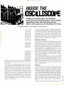
Inside Oscilloscopes -Application rules you should know
Before and after clock -page 45
PROJECTS YOU CAN BUILD
Digital Cribbage Board-modern day computer scoring for an
old card game
Before and After Clock -see the time as you tell it
Adjustable Timer-the beginning of many new projects
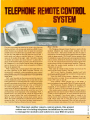
Telephone Remote Control System -let the touch -tone
signals trip in -house switches
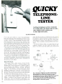
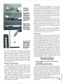
Quicky Telephone Tester-are your lines polarized correctly?
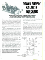
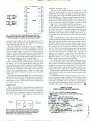
Power-Supply Balance Indicator -the test -bench designer's
tool
Identifying unknown IC's -page 32
SPECIAL COLUMNS
Saxon on Scanners -some good news and some bad news
Jensen on DX'ing- Listen to the lands of the tango, cumbia,
mariachi, and huayno
Friedman on Computers-what a hard -disk system can do
for your personal computer
Telephone BSR system -page 69
DEPARTMENTS
Editorial -you're eyeballing a collector's item
Letter Box -we get letters
New Product Showcase-consumer goodies we all can use
Bookshelf-from tomes to catalogs
1
EDITORIAL PAGE
Volume 3, No.1
JANUARY/
FEBRUARY 1986
The Magazine for the Electronics Activist!
You're eyeballing a collector's item!
Ifs a new year for Hands -on Electronics and were bringing to our readers a more exciting
magazine! Let me tell you about some of the highlights.
The people at Dick Smith Electronics cooperated with the editors of Hands -on Electronics
in the generation of a special 16 -page construction section in this issue. The projects presented
are some of the most often requested by builders of the editors and Dick Smith Electronics. We
put them all together in one special section. All project parts are available in kit form making the
building experience enjoyable and brief. Turn to page 53.
In this issue you find the first of a series of FactCards prepared for the project builder. They are
located right after page 38. Clip these valuable cards and save them. More will follow each
issue. In time your card collection will be an invaluable asset and will find its place on your
workbench.
There are two projects in this issue that are real sleepers. They may become the most talked
about projects in 1986. They are the Digital Cribbage Board (page 23) and Telephone Remote
Control System (page 69). In fact you'd best hang on to this issue; don't lend it to friends. The
Editor is forecasting a sell out, and that includes office copies, too!
Julian S. Martin, KA2GUN
Editor
Composition and interior design by
Mates Graphics
Hugo Gernsback (1884 -1967) founder
M. Harvey Gernsback, editor -in -chief
Larry Steckler, CET, publisher
Art Kleiman, editorial director
Julian S. Martin, KA2GUN, editor
Robert A. Young, associate editor
Cover photography by
Walter Herstatt
Brian C. Fenton, associate editor
Byron G. Wels, K2AVB, editor and associate
Carl Laron, associate editor
Ruby M. Yee, production manager
Robert A. W. Lowndes, production
associate
Karen S. Tucker, production assistant
Geoffrey S. Weil, production assistant
Jacqueline P. Cheeseboro, circulation director
Arline R. Fishman, advertising coodinator
BUSINESS AND EDITORIAL OFFICES
Gernsback Publications, Inc.
200 Park Ave. S., New York, NY 10003
212/777 -6400
Chairman of the Board: M. Harvey Gernsback
President: Larry Steckler
NATIONAL ADVERTISING SALES
(For Advertising Inquiries Only)
Joe Shere
1507 Bonnie Doone Terrace
Corona Del Mar, CA 92625
714/760-8697
JI!1
back
Hands -on Electronics, (ISSN 0743 -2968) Published by- monthly (Jana "Feb., March April. May Ju n e. July Aug., Sept. Oct. Nov Dec. by Gernsback
Publications. Inc.. 200 Park Avenue South, New York. NY 10003 Second -Class postage pending at New York, NY and at additional mailing offices One -year.
six issues. subscription rate U.S.A. and possessions $14.00. Canada $17.00, all other countries $21.00. Subscription orders payable in U.S. funds only,
international postal money order or check drawn on a U.S.A. bank. U.S. single copy price $2.50. c 1985 by Gernsback Publications, Inc. All rights reserved.
)
Printed in U.S.A.
Postmaster Please send address changes to Hands -On Electronics, Subscription Dept..
P.O. Box 338, Mount
Morris, IL 61054.
stamped self- addressed envelope must accompany all submitted manuscripts and or artwork or photographs if their return is desired should they be rejected.
We disclaim any responsibility for the loss or damage of manuscripts and.'or artwork or photographs while in our possession or otherwise.
A
As a service to readers, Hands -on- Electronics publishes available plans or information relating to newsworthy products, techniques and scientific and
technological developments. Because of possible variances in the quality and condition of materials and workmanship used by readers, Hands-on Electronics disclaims any responsibility for the safe and proper functioning of reader-built projects based upon or from plans or information published in this
magazine.
2
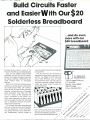
Build Circuits Faster
and Easier With Our $20
Solderless Breadboard
...and do even
more with our
$40 breadboard
Introducing the plug -in world of AP
Product's versatile, low cost breadboards.
Now you can design, build and test
prototype circuits just like the professionals... and make changes in seconds.
No messy soldering or desoldering. No
more twisted leads or damaged
devices.
With our ACE 109 and 118 blue breadboards, you simply plug in components
and interconnect them with ordinary
hook -up wire. All sizes of DIPs and other
discrete components up to 22 gauge
lead diameters snap right into the
0.1 "x 0.1" matrix of the solderless tie
points... anywhere on the layout. You
don't need expensive sockets or special tools. Buses of spring clip terminals
form a distribution network for power,
accommodate most
DIPs
and discrete
components.
The ACE 109 has Iwo terminals for
separate voltages plus a ground connection. The larger ACE 118 offers the
same three terminals, plus an additional terminal which can be used for
clocking or another voltage. The back plates are heavy steel to keep the
boards stationary.
A P PRODUCTS
INCORPORATED
9325 Progress Parkway
P.O. Box 540
Mentor, Ohio 44060
800 -321 -9668
(Ohio, 216/354 -2101)
/
/
ground and clock lines.
AP Products 100 series breadboards
give you all the functions and flexibility
of more expensive circuit evaluators.
The spring terminals have mechanically independent contact fingers to
/
/
/ \\
Don't wait. These low prices won't last forever.
See your local AP Products dealer today, or
send for a list of dealers in your area.
CIRCLE 706 ON FREE INFORMATION CARD
/
0Sl
\-\
\x,P
`e5
G\
Paa 0\
,\OC`
/
Óea
e
'
Ò,ot\
0g
a0) Q`
0
0
0a
aß,6
pia
/\5/
/
50
DOS
Vintage Radio Kit
Help! Is there someone or some corn pany that sells a kit of parts for the
Vintage Radio published in your Fall
1984 ( #2) issue of Hands -on Elec-
the "Build an Antique Shortwave Receiver" (Reinartz 2) that appeared in the
Spring 1985 issue of Hands -on Electronics, should shortwave fans be interested!
tronics?
repeat -Heeelp! M.B., Richboro, PA
Yes! First, many readers write to us for
plans on the "1920-Style Wireless Receiver" (we called it the Unidyne) that
were published in the above issue. The
issue is still available, although the supply is limited. You can obtain your back
issue by writing to our New York office.
Be sure to include $4.00 for the issue
5V -15V
I
and $1.00 for postage and handling.
A kit of parts is available from Tech nicraft Electronics by writing to them at
A Blink May Be a Boo!
My baby has a small teddy bear and
I'd like to replace the eyes with a pair of
alternately -flashing LED's. Have you got
a schematic can use?
R.T., Fresno, CA
Yes, but first a brief word. Childrer
are usually afraid of the dark, because
they are unable to orient themselves. A
small night light, kept in the same place
all the time, eliminates that fear. Also,
when you add the LED eyes to that teddy
bear, don't be surprised if everybody
else says it's cute; but the youngster
suddenly becomes afraid of it. That kind
of thing has happened more than once!
I
For Better Hold Ups
your Summer edition, 1985, page
74, the story "Put Your Telephone on
Hold" makes mention of 48 -volts DC originating at the telephone exchange. In
my area, that voltage is 52.5 -volts DC.
The voltage at my telephone is 51.7.
338 Katoomba Street, Katoomba
In
N.S.W. 2780, Australia. Send two International Reply Coupons for a response
on their latest prices and information on
other vintage radio kits.
The above information holds true for
I
24ocrgA/4 I
rr
yin$
Volume
Metal/
Basic Pipe Locator
1
assumes you
know absolutely nothing!
It will show you what the
components look like,
how to connect them into
the circuit. even how to
go on with further experiments with your circuits
when they are finished.
Fun Way
Amplifier
1
Flasher
Cat
Volume 2
DICK SMITH'S
Fun Way Volume 2 takes
over where Fun Way 1
FUN WAY
INTO
ELECTRONICS
Join the thousands of people, young
and old, who have discovered Dick
Smith's Fun Way Into Electronics.
Electronics should be fun, but for too
often. R is presented as a difficult mysterious subject. Even books for beginners
have not been successful presented
as successful in breaking down this
barrier. Dick Smith Electronics changed all that with the Fun WaySeries. From
the very basics of Fun Way One through
to the advanced projects of Fun Way
Three, electronics is dealt with In a fun
way that's really easy to understand &
most of all enjoyable!
I
sx.
finishes, with 20 exciting
new projects to try out.
But these projects are
different! They're all built
the modern way- on printed curcu it boards. Which
means, of course. all
components are soldered into
$650
Build your own intercom 8
use it around the home.
Practical simple to build
with the intercom amplifier
Make it as the latest to elec- above (Project 101
tronic jewellery, or a burglar Cat K -2638
warning light etc Thechoice
$
is yours and ft's easy!
Cat K -2621
895
Shortwave
Receiver
LED
Dice
-1
79$
cations, emergency services
and amateurs etc Easy and
fun It. build.
Cat K -2640
Touch Switch
Eve wondered
buttons
those
orked"
this touch switch yourself
and you'll be able to work d
out Variety of functions
explained.
Cat K -2628
Volume 3
Cat B -2610
Mono Organ
Snazzy little circuit uses
the back of the PCB as the
keyboard, Play e tune - it's
easy
Cat K-2626
tions or, with simple modifi-
Cat B-2605
The logical progression
for those who have worked through Fun Way
Volt and 2. Its for the
mom advanced hobbyist
because Fun Way Volume
3 projects are all based
on integrated Circuits.
$65o
You will be able to tune a
variety of short wave sta-
$695
$695
j.
t.
Extremely handy tor localtW pipes, wires, etc in walls
before dnlhng noies So,prlsmglyecircuit for such
a simple circuit
Cat 6.2633
Intercom
Cat B -2600
$495
Use to make the intercom
(project 18) or use as a
genera' purpose amplifier.
Really handy, good sound
output too.
Catgut
oo
$550
Electronic
Siren
Home/
Car Alarm
Very practical! You could
Just what you need with use this alarm to protect
the alarm! Also makes a your home and property!
great sound effects circuit - U ses a ny of the normal alarm
and Fun Way 2 tells you triggering devices
what to do!
Cat K -2635
Cat K -2636
$
5495
Ding
Dong Doorbell
Ves it actually sounds like
a great old fashioned door.
bell But it's electronic: and
you can build it'
Cat K -2622
tae
construction
ORDER TOLL FREE 1 -800 -332 537
$4 SO
include
These kits do NOT
instructions All information
Fun Way
is published in
2, which is necessary
can begin on
any kit.
iw-
Auto Battery/Alternator Monitor
dropped the voltage an additional 4
other fact, a Radio Shack 276 -1067
works equally well in place of the
SK3638 SCR. tried both.
problem. He built three (3) units at the
same time and all three appear to have
the same problem: it would appear that a
difference in vendors of the LM3914 and
a variation in lead lengths in the vehicles
may be creating a situation whereby
more than one LED will be lit at the same
time even when in the "Dot Mode" of
operation. All the units work fine on the
bench, but they begin to act up when
placed into the car.
D.D., Skokie, IL
I
H.K., Caldwell, ID
At the consumer end of the line the DC
voltage across the line should be a nomina/48 -volts DC. We received several letters about this telling that the voltage
varied from 41- to 56- volts. What good is
a standard if you can't deviate?
Almost Like Remote Control
know it's an old problem in basic electricity, how to wire an upstairs lamp so it
can be controlled from a downstairs
switch and an upstairs switch. want to
use the same kind of set -up to control a
different electrical circuit.Can you save
me some head-knocking?
B.G., Dallas, TX
.
I
0
TO
AC
LINE
SPOT
You weren't very specific, but here's
the circuit I think you're looking for
Binary Bingo
Universal
Timer
¿yVoG .3
LED Level
i
Cricket
Display
Hook it up to your stereo
and it can warn you of dangerous overloads. Looks
pretty nifty too - the LEDs
light up in time to the music!
Cat K -2637
$
A.
8
project it's a
fun game - but even more it
demonstrates binary numbers very well. And they're
the basis of all computers!
C'mon, Guvnor - leave the It seems pretty simple to
auto alone. That's the Fun play
but try it!
Way 3 Minder telling vilCat K-2668
lains that It is looking after
$
the car! It's actually doing
much more- makes a greet
'lights on' warning and
well
'door open' warning as
as a pseudo burglar alarm.
Cat K -2660
A great school
$550
Here's a ton of fun! Hide
the cricket when the lights
go out it starts chirping.
Turn the lights on or make e
noise and it stops. Makes it
so hard to find!! It really is
infuriating!
Cat K-2863
S95
. .
.
You can turn this audible
alarm into just about any thing requiring sound Even
for Morse code- and it's tun
to learn!
LED
=
$795
yg
A
of counting applications
or just for fun!
$795
Cat K -2639
Wireless Mic.
Just like
Transmits in
spy monies!
movies!
to
any standard FM radio in
another room or next door,
etc. You can really hear it
*6so
7
Cat K -2631
all!
Pocket Transistor Radio
Building this small set will
teach you a lot about the
fundamentals of radio. And
then you'll have fun using it
too'
4795
Cat K -2627
Mini Synth
U1' PokeYlth
this
1>e
d
s
Youll heve
dpnY risk
losing
vrhkht1no
Prol
one
dlgitsl
hMa the
bendilog
Cat K -2623
Counter Module
perfect introduction to the
world of integrated circuits.
And this useful counter can
be used for a huge variety
Two-up
®h,®
Australia's 'national game'
has finally been converted
to electronics. And you don't
have to find any King
George pennies! Simulates
the throw, the spin and the
Y
armedh
teaches
cults 266Zo
CatK
citrt-
y
j/rv/
Want an amplifier for your
'walkie' stereo or radio?
Don't be tied to 'phones:
use this project and listen
in comfort! Or you can build
this into a mini PA amplifier.
Cat K -2667
1495
home study. While your answer did fit the
question, think it could be improved
upon. The University of the State of New
(Continued on page 18)
I
FUN WAY ONE
VALUE PACK
Projects 1 - 10
Enables you to build any
of the first ten Projects
in Fun Way One. And
because the
components are not
soldered, they are all
reusable so you can
build any other of the
first ten projects, too.
Cat K -2600
It's a real beauty, this one'. a
real 'live' musical synthesiser - and it's live because
it uses YOU as the note
generator! You get an
amazing range of control
over the sound.
Cat K-2669
FUN WAY ONE
VALUE PACK
Projects 11 - 20
Contains the more
specialised components
required to complete the
last ten projects (11 20) in Fun Way One.
Note: you will also need
the 1 - 10 kit above to
build these projects.
Cat K -2610
$1995
FUN WAY THREE
final result. Come in spinner!
Cat. K -2661
$
Mini
Stereo Amp
tronics engineering degree through
41995
/1
Morse
Code Trainer
Learn by Degree
In your Letter Box column in the Summer 1985 issue of Hands -on Electronics,
you offered advice to an individual who
was interested in obtaining an elec-
cause more than one LED to light at
once. The first red LED would be lit very
dimly if viewed in darkness. That problem has been traced to poor filtering on
the input line. Install a5 -10µF tantalum
capacitor across the pins where the voltage is supplied to the IC. The same
effect can be had by a 1 -1.LF capacitor
from pin 5 to the common (V-) lead. Both
changes may be made, but chances are
LAMP
s too hard? Time them
with this great little timer. It
E9
really works- set it fora few
seconds to 15 minutes!
Cat K-2824
larities are shown reversed in Fig. 5 diagram. The pictorial wiring in Fig. 4
shows them wired correctly.
Check for RFI generation by tuning
the car radio to a quiet spot on the upper
end of the AM band with the engine run ping and the Monitor operating. There
should be no interference when the
above capacitors are added.
The unit does have a tendency to
break into parasitic oscillation and
would, under certain circumstances,
I
SPOT
good that only one of them will be required-most likely the latter one.
The published diagram shows the
Mode pin (9) connected to either pin 11
for a dot display or to pin 3 for a graph
display. Try pin 9 floating for the dot display, andjumpered to pin 3 for the graph
mode. Pin 11 connection is used only
when cascading more than one LM3914
for 20 or more dots.
Another problem is that the LED's po-
Update
Recently, a reader who had built the
Auto Battery /Alternator Monitor project
(page 49, Spring 1985) experienced a
volts; and now have a nice hold feature
built into the telephone set itself. One
a
Mini
Color Organ
Your very own disco colour
organ - but ours is battery
operated - so it's much
safer than mains devices!
Connect it to your radio,
cassette or stereo fora real
lightshow!
Cat K -2664
of the most popular
Hj
$
TOLL FREE 1 -800-332 537
kits in the
two
Buy this kit with
the book FREEI
And what velue. boo k ... and we throw in project (known to his
Cricket
Fun Way Three
the Miniature
the Electronic
both
get
Yes, you
a bonus, the
i2ä9Ó, and as
friends as
togetherivalued
Fun Way projectboo k itself at no extra charge!!
Fun Way Three
Cot K-2670
$2495
a
s
-Eim
A
-N-..-
1-]
1:1
¡j
h
_\__.
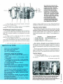
Automatic Digital SWR /Wattmeter
to indicate the antenna matching con dition: Green for good, yellow for not very
good, and red for a mismatched con
The MFJ -818 automatic, digital SWR/
wattmeter has bright- orange LED digits
on the SWR display. But more impor-
dition.
The MFJ-818 meter, which measures
inches, carries a one
5 % x 41/4 x
year unconditional warranty, and retails
for only $89.95. In addition, if you order
tantly, this SWR /wattmeter is automatic,
eliminating three steps in reading SWR:
switching to set, setting the meter needle
for full -scale deflection, and switching
back to SWR to read. The meter reads
SWR 1:1 to 1:9.9 directly and instantaneously. There is no need to adjust
the SWR set knob!
only
1
directly from MFJ, you get
money back guarantee.
delighted, send the product back within
30 days for full refund, less shipping.
The MFJ -818 can be charged to your
Visa or Mastercard account if you wish to
order over the phone. Call 800/647 -1800
toll -free, or write to: MFJ Enterprises,
Inc., P-O. Box 494, Mississippi State,
MS 39762.
°
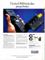
Locking Leads For DMM
CIRCLE 736 ON FREE INFORMATION CARD
The MFJ -818 reads up to 200 -watts of
RF output on its LED bargraph display.
The 12 -bar display indicates the on -air
power level instantly and correctly to
show instantaneous peak power. The unit
features a tri -color indicator that lights up
TPI has eliminated the nuisance of test
leads accidentally disconnecting from the
meter. A thumb screw expands the banana
plug inside the meter jack for a tight,
secure connection. The LTL1000 is ideal
for low-voltage and resistance measure-
ments. Its silver-plated contacts minimize
thermal EMF and contact resistance. The
LTL1000 also features rubber shielded banana plugs for maximum safety, and soft
and flexible cables that have strain reliefs
at both ends. Ratings are 1000 -volts rms
'Economy Soldering Iron
>
`:,,¿:
Stereo
En'on
a9vrcei'cc
stecabi heap in.aZenpryers
h¡ -sVyou
your
son
and create ches to
attaches
test stereo rrow
The eretiact
oteawéry
5tefeo
General purpose main powered iron that s ideal for all those
hobbyist and technician jobs. Comfy, tapered handle and nicely
balanced iron for hours of fatigue -free use.Stainfess steel barrel
and 110 volt, 30 watt element is just right for most assembly or
repair soldering. Great beginner's iron, tool Comes ready to use
with hints on soldering.
'a
Wait./
3n0
.,ar
/ Transistor Nipper qVL
Cat T -1
.
blt
Ideal for PCB work. Very sharp preCiswn
cut with long life cutting edrge.3.7"
bengce¡,Nhwh
small unit
with
spring
a'
ini
JpG
j
tt
;
4.
t
\
Solder Stand with
The helping hand when yu need n
most when you have a'hot stick'
your hand! Heavy die-cast base,
in
solder stand. clips for holding PCB.
etc - plus a unique magnifying lens
for those close assembly jobs.
Cat T -5710
$
r
5595
rrY//
OLOP
SEN
GE EE
"5
let
AND
CP1P PP AND
S pEpÉEM
KITS.
Y11N
pU5 C
90DE{1.
U5
CftApno.0
PLUS
EAF
/r
5
0 K'
Rrj
Magnifier!
qS
$995
and
WA
wh semF .c/t
u
won't1 Cat T-3570
COM
oh
ro35' cutting
conductors
inej.04)
tip will reach into places others
'
I
fr
-3205
eedle
Nose Plier
te up
Precno-
I
jaw. Ideal
IT
.,
CIRCLE 728 ON FREE INFORMATION CARD
f1MB8,g7q,
U
30-day
a
If not completely
Off
Ut
y0
N1
BEN'
YO
Et
WE'LL.
PL
sort pNO
GO SNIPP OPyI
EE C
JEP EP
0U
0
S
EVERYTHING FOR THE ELECTRONICS ENTHUSIAST
STORES AT:
11H
ELEOTRONIS
INCORPORATED IN THE STATE OF CALIFORNIA
NEARLY 70 STORES
IN THREE COUNTRIES
2474 Shattuck Ave., Ph:(415) 486 0755
REDWOOD CITY: 390 Convention Way, Ph:(415) 368 8844
SAN JOSE: 4980 Stevens Creek Blvd, Ph:(408) 241 2266
STORE HOURS: San Jose & Berkeley 10 AM - 6PM EVERYDAY
Redwood City 10AM -6PM Mon - Sat; 12 -5PM Sunday
MAIL ORDERS: PO Box 8021, Redwood City, CA 94063
HEAD OFFICE: 390 Convention Way,
BERKELEY:
Redwood City, CA 94063
NANDIING - ALL ORDERS
S
1.00
PLUS SHIPPING
i,
INSIDE USA 5% OF ORDERTOTAL
(MIN S1 SO)
OUTSIDE USA 10% OL ORDER
TOTAL (MIN $3.00)
ORDER TOLL FREE 1 -800 -332 537
CIRCLE 717 ON FREE INFORMATION CARD
and 10-A continuous current. It's priced at
$15. For more information, write to Test
Probes, Inc., P.O. Box 2113, La Jolla, CA
92038: Tel. 800/368 -5719; in California,
800/643 -8382.
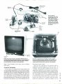
Lap Computer
The portable ZP -150 lap computer, a
diskless unit from Heath, is being offered
as a fully assembled computer product. It
weighs only 7.7 pounds and has an LCD
(Liquid Crystal Display) screen built into
its flip top. It is the first lap computer to
use Microsoft WORKS, a ROM -based
software package developed by Microsoft
the°
Corporation, which is compatible with
MS -DOS machines. The ZP-150 has 224
kilobytes of ROM and 32 kilobytes RAM
1
1rr
CIRCLE 748 ON FREE INFORMATION CARD
/1
ROY THEOF
8010775
LED
0ye
Cat K -3335*
$
*
T ch
KO
34
95
CIRCLE 734 ON FREE INFORMATION CARD
and K-band LED and audio indicators.
The RD 9 also features Electronic Data
Interference Terminator (E.D.I.T.) circuitry, which assures accurate radar signal
detection by helping to eliminate er-
roneous signal interference. Housed in a
pocket -sized carrying case, the dual-conversion, superheterodyne radar detector
can be installed in almost any size vehicle.
A two -position highway /city selector
switch allows the user to select unfiltered
(Continued on page 8)
OR moo in/
The Dick Smith
Home Alarm
What a superb kii This highly developed design oilers
features which you'd normally find only on units costing
more.
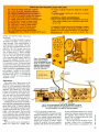
FEATURES
o Security key operation for both alarm function and box
access
2 instant and six delay sectors. capable of handling
normally open or normally closed in any mix
o Inbuilt mains power supply with battery backup
o Siren (up to two speakers) PLUS bell(relay)output and
also capable of driving telephone diallers, strobes. etc.
Inbuilt local test facilities, including buzzer
Complete kit including case and all electronics.
kit! Cat K -3240*
avY511 995 wid
Cat K-3424
411
i/
SailP
It
O
k11
Ia
To assist
*
***
"to
averoge
us
* *
EA
atia.y $9995
rTV
astat'
detetmi'
ded
W u In We
have
Vo
follows
sultoble toteach
os
ktt
toting on ltaWe tor beginnershobbVi
IC9
,
%%
--..
Don't spend a fortune buying
a tachometer - build your own
and save! Displays engine
speed in an analog form in an
illuminated row of LED's. Instructions included - a great
Negative Ion Generator
You've heard all about Negative Ion Generators and
their benefits. now buy the kit and find out what its all
about. Many commercial
run
the
our kit is safe- it runs on 1 2V DC, which also means
that you can put one in your car! Kit includes exclusive
Dick Smith emitter heed, power peck end tough moulded
plastic case.
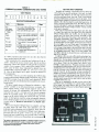
Two Compact Radar Detectors
Uniden has added two compact radar
detectors to their line. The model RD 9,
measuring only 4.2 x 2.76 x 0.71inches, may be the smallest self-contained
radar detector currently on the market. It
is very sensitive. and features separate X-
user memory, which is expandable to 416
kilobytes.
Built into WORKS are several business
programs: including PLAN, a subset of
Microsoft's Multiplan; WORD, a subset
of the powerful word processor WORD by
Microsoft; FILE, a recently developed
Data Base Management System (DBMS);
CALENDAR an appointment secretary;
TELCOM, a telecommunications pro gram complete with auto -dialing capability, and BASIC, a large subset of
popular programming language GWBASIC. In addition to the ROM -based
business software, the ZP-I50 has a paral
lel printer port, an RS -232 serial port, an
audio cassette player port, and a telephone
jack to be used with the internal 300 -baud
modem. The unit is powered by ten AA
alkaline batteries, which allow 8 -10 hours
of operation. An AC -power converter is
supplied for use on standard 117 -VAC
lines.
The portable ZP-150 lap computer,
priced at $995.00 and available through
Heath Company and 64 Heath /Zenith
computers and electronics stores nationwide, is just one of over 400 products
offered in the latest Heathkit Catalog. For
your free copy of the Heath catalog, write
to Heath Company, Dept. 150 -586, Benton Harbor, MI 49022.
teGh IqUebeM1
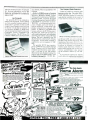
VCR Theft Alarm
Masthead Amp
That VCR sitting on top of your TV set is a
very expensive appliance. It is also portable
and marketable, which makes it a prime
target for thieves The simple alarm described
here will sound off immediately the VCR is
lifted - and it makes a lot of noise. The circuit
could also form the basis of a burglar alarm
for an entire house.
Don't put up with lousy TV
(we can't do much about the
content but this kit should fix
the pie!) Reduces or even eliminates snow, also great for
reducing ghosting. Covers both
UHF and VHF TV Bands plus
FM bards Includes 110V supply in Price.
ßs39
Cat K-3423
Cat K -3232
$2995
Eit
I The
Economy
Car Alarm
This alarm senses the
95
gr.
voltage drop in your car's
electrical system when a
thief breaks into it. Visual
warning for thieves so
chances are they will not
even attempt a break-in.
Cat K -3250
*
1
A NOW D/N
sac
The problem with 99% of car alarms is that they
cannot prevent the thief who breaks a window
and reaches in for the goodies While this kit
won't prevent the window being broken, it will
protect your property inside the car. Silent ultrasonic rays detect any movement and trigger the
main alarm system.
**
/
cf*//A Cti? Plfareci7oyf
Ultrasonic Detector
d
_/
Cat K -3251
L
USE WITH YOUR EXISTING ALARM
OR THE DICK SMITH CAR ALARM Cat
K
-3252
ViLJ
$i 995
ORDER TOLL FREE 1 -800 -332 537
MUST LIQUIDATE
PUBLIC NOTICE
We are authorized liquidators of
consumer products that must be
quickly sold by manufacturers at
AT FAR BELOW DEALER COST!
drastic price reductions for many
Computer Products
Famous U.S. Brand
reasons, such as
Discontinued lines. Last year's
models. Distributor surplus. Cancelled orders. Out -of- season
products. Tailends of inventories.
Whatever the reason for the liquidation, you are assured of fine
quality at money saving low
prices! Supplies are limited.
Order now!
Dot Matrix
PRINTER
Factory reconditioned!
Factory warranty!
Compatible
with C64,
SX64, VIC20,
Educator 64,
Plus /4 and C16
Here's a great opportunity to
add a fine quality printer to your
Personal Computer...at a BIG SAVINGS!
Now you can get neat, clean printouts of reports,
correspondence, mailing lists, charts, inventories,
financial figures...or anything else you have in
computer memory. And it all comes out at the
speed of 60 characters per second.
LINE FEED SPACING:6 lines per inch in character
mode or 8 lines per inch selectable. 9 lines/inch in
graphic mode.
LINE FEED SPEED: 5 lines per second in character mode. 7.5 lines per second in graphics mode.
PAPER FEED: Friction feed (Tractor feed is optional. Available from dealers nationwide.)
PAPER WIDTH: 41/2" to 81/2" width. Up to 10" with
optional tractor feed.
MULTIPLE COPIES: Original, plus two.
SIZE: 13 "W x 8 "D x 31/4" H. WEIGHT: 81/2 lbs.
These are factory reconditioned units that look and
work as good as brand new. And they're backed by
the manufacturer's standard new product warranty!
Sorry, we're NOT permitted to print the famous
brand name in this ad. But we can "tell all" if you
phone us Toll-Free: 1-800-328-0609.
PRINT METHOD:Bi- directional impact dot matrix.
CHARACTER MATRIX: 6 x 7 dot matrix.
CHARACTERS: Upper and lower case letters,
numerals and symbols. All PET graphic characters.
GRAPHICS: 7 vertical dots, maximum 480 colCHARACTER CODES: CBM ASCII code.
PRINT SPEED: 60 characters per second.
MAXIMUM COLUMNS: 80 columns.
CHARACTER SPACING: 10 per inch.
Liquidation
Price Now Only
New!
Credit card customers can
order by phone, 24 hours
a day, 7 days a week.
$119
iii
xlmw.cra
day
Limited
Factory
Warranty rC.O.M.B.
Your check is welcome!
No delays in orders paid by check.
Item H -796
Direct Marketing Corp.
Liquidation due to manufacturer's overproduction. The 1 14605 28th Ave. N. /Minneapolis, MN 55441 -3397
modem plugs into Commodore 64K or SX64, so you
Send t'3e- followingItems. IMinnesotaresidentsadd6 %salestax.
can access new worlds of information on a subscription I Allow
weeks for delivery. Sorry,
C.O.D.)
hookupp to phone.
basis. Has modular jacks for quick
q
p
Works on TouchTone and Rotary (Pulse) systems (not!
PBX). Super intelligent software, completely menudriven. 30K software buffer. Auto dial, auto answer.
Price includes FREE trial subscription to over 521
database services.
l
Mfr. List:
$124.95
Liquidation Price
1$4.00
Item H- 796 -63646 -00 Ship, handling:
l
Dot Matrix Printer(s) Item H- 796 -83831 -00 at $119 each
plus 57 each for shipping and handling.
Modern(s) Item H- 796 -63646 -00 at S19 each plus $4
each for shipping and handling.
-64K
My check or money order is enclosed. (No delays in
processing orders paid by check, thanks to Telecheck.)
VISA
MasterCard®
Charge to my:
Exp
Acct. No.
I
PLEASE PRINT CLEARLY
Name
C.O.M.B.
Direct Marketing Corp.
Authorized Liquidator
14605 28th AVENUE NORTH
MINNEAPOLIS, MINNESOTA 55441 -3397
8
CIRCLE 744 ON
FREE INFORMATION CARD
Toll -Free: 1- 800 -328 -0609
90
MODEM
Audio Video Cable
Hitachi recently introduced the latest in
its line of audio /video cable, which is said
to offer superior reproductive quality. The
cable uses linear -crystal /oxygen -free copper (LC -OFC), a recent audio /video technology development from Hitachi. The
Price subject to change after 60 days. Sales outside
continental U.S. are subject to special conditions. Please call
or write to inquire.
Factory
V,:.
position switch permits selection of either
audible or visual, or combined alert when
radar is detected. The unit may be either
visor- or dash- mounted. A power cord
supplied with the RD 9 can be used for
either positive or negative- ground vehicles. Its suggested retail price is $269.00.
The other unit, the RD 35, also features
E.D.I.T. circuitry and, like the RD 9, is
protected by a I2 -month warranty. The
RD 35 is lightweight, compact and offers
state -of-the art features and quality. Because of technology efficiencies inherena
in its design, it is priced at only $139.95.
The RD 35 may be either dash- or visormounted and warns the operator by sound
and a red warning light when X- and Kband police radar signals are detected. Its
E.D.I.T. superheterodyne circuitry is designed to virtually eliminate false -alarm
sources, such as nearby microwave relay
stations, radar door openers, and aircraft
and boat weather radar systems.
For more information on the RD 9 aad
RD 35, write to Uniden Corp. of America, 6345 Castleway Court, Indianapolis,
IN 46250.
Item H- 796 -63831 -00 Ship, handling: $7.00
FCC Approved!
64K
(Continued /rom page 7)
sensitivity for highway travel or filtered
sensitivity for urban travel. A single three-
$199.95
Mfr. List When New
umns. Dot addressable.
New Products Showcase
Address
City
Zip
State
Phone
Sign here
J
linear -crystal cable provides dramatically
lower distortion and reduced signals loss
compared to conventional cable. One critic claims that using the cable is equivalent
to upgrading a full level in loudspeaker
quality.
Hitachi researchers suspected that a
major source of distortion and signal loss
lay in the boundaries between crystals,
which act as a gap that electrical impulses
have to cross. One way to minimize the
problem, they reasoned, was simply to
reduce the number of crystals. To do so,
(Continued on page 18)
With NRI training at home, you can...
And you can start by actually building NRI's
16 -bit IBM -compatible computer.
You can create your own bright,
high paying future as an NRI trained
computer service technician. The
biggest growth in jobs between now and
1995, according to Department of Labor
predictions, will occur in computer
service and repair, where demand for
trained technicians will double. There is
still plenty of room for you to get in on
the action
you get the proper
training now.
-if
Total computer systems
training, only from NRI
To learn how to work on
computers, you have to get inside one.
And only NRI takes you inside a
computer, with total systems training
that gives you hands -on experience with
computers, peripherals, and software.
As part of your training, you'll build a
Sanyo MBC- 550 -2, which experts have
hailed as the "most intriguing" of all the
new IBM -compatibles. The Sanyo even
surpasses the IBM PC in computing
speed and graphics quality.
Even if you've never had any
previous training in electronics, you can
succeed with NRI training. You'll start
with the basics, rapidly building on the
fundamentals of electronics until you
master advanced concepts like digital
logic, microprocessor design and
computer memory. You'll probe into
electronic circuits, using the exclusive
NRI Discovery Lab and professional
Digital Multimeter, that you keep.
You'll assemble Sanyo's intelligent
keyboard, install the power supply and
disk drive, and attach the high resolution monitor -all the while performing
hands -on experiments and demonstrations that reinforce your skills.
Learn to service
today's computers
As you complete your Sanyo, you
grasp the "secrets" that qualify you for
a new career. You'll learn to program in
BASIC and machine language. You'll
use utility programs to check out the
operation of the Sanyo's 8088 microprocessor (the same chip used in the
IBM PC). And you also get over $1,000
worth of software, including WordStar
and CalcStar.
Most importantly, you'll understand the principles common to all
computers. Only a person who fully
understands all the fundamentals can
hope to be able to tackle all computers.
NRI makes sure that you'll gain the
knowledge and skills to maintain,
troubleshoot and service computers.
Learn at home in spare time
With NRI training, you'll learn at
home on your own time. That means
your preparation for a new career or
part-time job doesn't have to interfere
with your current job. You'll learn at
your own pace, in the comfort and
convenience of your own home. No
classroom pressures, no rigid night
school schedules. You're always backed
up by the NRI staff and your instructor,
who will answer questions, give you
guidance and be available for special
help if you need it.
Let others worry about computers
taking their jobs. With NRI training,
you'll soon have computers making
good paying jobs for you.
Send for Free NRI Catalog
Send the post -paid reply card today
for NRI's 100 -page catalog, with all the
facts about computer training plus
career training in Robotics, Data
Communications, TVNideo Servicing
and many other fields. If some other
ambitious person beat you to the card,
write to NRI at the address below.
MCH
00 LS
McGraw -Hill Continuing Education Center
3939 Wisconsin Avenue, NW
Washington, DC 20016
We'll Give You Tomorrow.
IBM is a Registered Trademark of International Business
Machines Corporation.
By Barmard de Backus
ULTRA -MINIATURE
5 VDC RELAY
D.P.S.T. LIGHTED
ROCKER SWITCH
,
par
snap mounts
Fuptsu s
FBR211NED005M20
High sensrtrvlty
$1.25 each
COIL 120 ohms
10 for 510.00
CONTACTS.
amp
Mounts In 14 pm DIP socket
rocker
115
'Orange lenshole.
In
x 14e"
16
contact.
1
amp
I,
$1.50
MINIATURE TOGGLE SWITCHES
ALL ARE RATED 5 AMPS @ 125 VAC
S.P.D.T.
S.PD.T.
(on -on)
S.PD.T.
(on-on)
(on- off -on)
Solder lug
terminals
Solder lug
terminals
51.00 each
10 for 59.00
100 for $80.00
PC style
non -threaded
"'-
bushing
754 each
10 for $700
S1.00 each
1
10
for $9.00
100 for $80.00
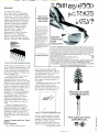
Multi- Circuit Board Projects
By R.A. Penfold
The Multi- Circuit Board Project
book contains information that allows
the reader to build 21 fairly-simple
electronic projects; all of which may
be constructed on the same specially
designed printed-circuit board. In
addition, wherever possible, the same
components are used in each design so
that, with a relatively small number of
13.8 VDC REGULATED POWER SUPPLY
These are solid state, fully regulated 13.8 vdc
power supplies. Both feature 100% solid state
construction, fuse protection, and L.E.D. power
indicator U L listed
/////////////
y
//
-I
,e
2
amp constant,
4
amp surge
518.00 each
3
amp constant,
5
amp surge
$25.00 each
8" P.A. SPEAKER
C T.S.
Model 883079
3.0 oz. ferrite magnet
Typical response
'\
CASE OF
SPEAKERS
1000 hzange
$
Power rating 15 watts max.
Drilled to mount line
matching transformers
200
13/4
-
EDGE
CONNECTORS
VDC''
DIA. x5 HIGH
ALL ARE 1.56' SPACING.
$2.00
$1.00
DIA. x 33/4 HIGH
6,400 mfd. 60 VDC
1rh- DIA
x
4'a HIGH
$2.50
9,700 mfd. 50 VDC
t1"
DIA x
HIGH
41/2
$3.00
31,000 mfd. 15 VDC
DIA
134
x
4' HIGH
$2.50
72,000 mfd. 15 VDC
2' DIA
x 43/4
HIGH
-'
22/44 EDGE CONNECTOR
PC. style
$2.00 each
+0 for $18.00
22/44 EDGE CONNECTOR
solder lug
$2.50
style
each
28/58 EDGE CONNECTOR
Pc. style
$2.50 each
10 for $22.00
38/72 EDGE CONNECTOR
3,600 mfd. 40 VDC
13/4
Board Projects
1\
COMPUTER
GRADE
CAPACITORS
2,000 mfd. 200
Multi- circuït
`,
$5.00 each
8 ohms coil
$3.50
PC style
185,000 mfd.
6 VDC
$1.50
2'2 DIA. x41R' HIGH
CIRCLE 739 ON FREE INFORMATION CARD
$3.00 each
43/88 EDGE CONNECTOR
PC. style
$4.50 each
TI SWITCHING POWER SUPPLY,
Compact, well -regulated switching power supply
designed to power Texas Instruments computer
vim
equipment.
INPUT
14 - 25 vac @lamp
12 vdc @350 ma
OUTPUT
- 5 vdc @1.2 amp
-Svtl% @200 ma
SIZE 4H -x414"
11/4"
I
sl
11
l
for $2.00
II
6
)S
4/
erase heads 2 -12VDC motors
drive belts pulleys 3 -12VDC
solenoids pincnwheels and nine,
mechanical parts These pan,
used On Other current modei
decks would toss several erne.our selling price il purchased
separately 5'+ x 312 x 3'
100 for $17.00
1010, 52.00
100 for $17
2.00
volt operation
retl jumbo T zx
size 51.00 each
1
e
$7.50 EACH
2 FOR
$12.50
BI -POLAR
MINI -PUSH BUTTON
jumbo T 1'a size
2 for $1.70
LED HOLDERS
Two piece holder
S PS T
nmally
8
for 65E
Red butttton
35e each
100 for 55.00
10
TOLL FREE ORDERS
1
-800-826-5432
-258.6666)
(IN CA:
1- 600
(213) 380-8000
hush,
1-
for jumbo LED
INFO
.
New. stereo cassette mechanism
Includes record /playback and
5
10
-, .,,!i'' c
a
5M
1010,51.50
FLASHER LED
11
T
Ai
4
100 for $13.00
fill
R
r-
l
STANDARD JUMBO
DIFFUSED T 1 V2
10
n
;.
l.1
111777TT,
560 high. segment L E D read
outs Mount n 24 Din DIP socket
CND -5148 red c c 75c each
DL -527 red. c a
75e each
GREEN
-
CASSETTE
MECHANISM
DISPLAYS
7
YELLOW
-
S
CI
RED
-1-r'li
á.
óG l$
$5.00 each
high
'SPECIAL PRICE*
DUALLLLEE..D.
l':
dDANTIT1ES LIMITED
L-
.
.
11.4.1111
-
for $3.00
FORE GN ORDERS
INCLUDE SUFFICIENT
SHIPPING
CALIF RE5 ADD 61 2
CIRCLE 709 ON FREE INFORMATION CARD
12
0
USAIAS300DSNiinemNG
components, it is possible to make any
of the projects by re -using the
components and printed- circuit board.
Each project comes with a circuit
description, circuit diagram,
component layout diagram, parts list,
and construction notes. All projects
operate from a 9 -volt battery, making
them a safe introduction to electronics
for the beginner.
Multi- circuit Board Projects
(published by Bernard Babani
Publishing Ltd., London, England) is
available through Electronics
Technology Today, Inc., P.O box 240,
Massapequa Park, NY 11762 -0240,
priced at $6.00 (including shipping
and handling).
Basic Electronics Technology
By Avis J. Evans, Jerry D. Mullen,
and Danny H. Smith
Texas Instruments has published a
one- volume 464 -page ready reference
to semiconductor circuits and systems.
The book is an overview of electronics
technology based on integrated
circuits. It explains simply and
thoroughly both the basic concepts and
CIRCLE 725 ON FREE INFORMATION CARD
the practical applications of electronic
circuits and systems. Engineers,
technicians, students, and technically
interested consumers will all find it a
valuable tool for learning and as
review or as a reference.
Basic Electronics Technology covers
most of the primary functions and
associated circuits that go into the
electronic systems that touch our lives
every day. It explains how
semiconductors and circuits work as
amplifiers and oscillators: in power
supplies, audio systems, AM /FM
radio, TV and other video systems, as
well as microprocessors and
computers.
The book's initial chapter explains
basic semiconductor theory, how
semiconductor devices operate and
what they do in a circuit, giving the
beginning reader a solid foundation for
the more complicated concepts and
applications that follow. Each chapter
contains a summary, followed by a
short quiz to reinforce the information
presented.
The authors of Basic Electronics
Technology combined their many
years of teaching experience and
hands -on knowledge to present an
easy-to- understand guide to basic
electronics theory, application, and
troubleshooting. Basic Electronics
Technology will be available through
bookstores and college stores at a
suggested retail price of $19.95.
Linear IC Equivalents And Pin
Connections
By Adrian Michaels
Linear IC Equivalents and Pin
Connections (Book No. 141), based on
(Continued on page 15)
Keep
a
ELETUIIJS BDuK CHUB
In Step With the Future ... Become
ti
I
:
Mtci.
TRANSDL'CIJt
PR(111 C7
HCltlh.
Part of the Fascinating World of Technology!
High -Tech How-To
Space Age Projects
1183
Robotics
Computers
Telecommunications
And much more!
Digital Electronics
Artificial Intelligence
Select 5 Books for Only;
&
1992
List $15.95
List $14.95
CONCEPTS Of
DIGITAL
ELECTRONICS
95
(Values to $107.75)
ilMC
1602
List $16.95
1531
List $17.95
1245P
1719
List $16.95 (paper)
List $18.95
1d.aC1'60NC PROJECT,
wit..
Mate
7007
'IT
PüOTOGRAPHI.K--
NOW TO
DESIGN BORO
Handbook of
TO
101
REMOTE CONTROL
DEVICES
EASY TEST
INSTRUMENT
PROJECTS
Practical Electronic Omits
IC
COOKBOOK
1690
1199
List $19.9
List $21.95
-
1277
800P
List $19.50 (paper)
List $21 95
1544
List $21.95
INTEGRATED
CIRCUIT
-
-..
1339P
1685
List $7.95 (paper)
List $17.95
VIDEO
READING
SCHEMATICS
ELECTRONICS
THEORY It PROJECTS
1529P
List $14.95 (paper)
TECHNOLOGY
V-
>i
1553
List $15.95
1241P
List $10.25 (paper)
1672
1699
List $18.95
List $19.95
'1474P
1431
List $12.95 (paper)
List $17.95
htRS
1'N3NORß 6 nt4cTYZ Of
&
guide to
mail order sources
for electronic parts
and components
LEDS
A
1909
List $21.95
1577
List $19.95
1599P
List $15.95 (paper)
1218
1539P
List $18.95
List $15.95 (paper)
1013
List $14.95
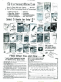
FREE When You Join Now
very good reasons to join
the Electronics Book Club
1536
List $14.95
FREE
,rva,a
DIGITAL ICS
1532P
List $12.95 (paper)
.4e
$6.95
Value !
%yP ct4,
G'e
f.
7
rELECTRWJ
P.O. Box 10,
Big Savings. Save 20%
to 75% on books sure to increase your electronics know-how
No-Risk Guarantee. All books returnable within 10 days
without obligation
Club News Bulletins. All about current selections
mains, alternates, extras -plus bonus offers. Comes 13 times
a year with hundreds of up-to- the -minute titles to pick from
Automatic Order. Do nothing, and the Main selection
will be shipped automatically! But
if you want an Alternate selection -or no books at all -we'll follow the instructions you give on the reply form provided with every News
Bulletin
Bonus Books. Immediately get Dividend Certificates with
every book purchased and qualify for big discounts of 60%
to 80%
Extra Bonuses. Take advantage of added -value promotions, plus special discounts
Exceptional Quality. All books are first -rate publisher's
editions selected by our Editorial Board and filled with useful
up-to- the-minute information
-
...
EuuK CLUE
Blue Ridge Summit, PA 17214
Please accept my membership in the Electronics Book Club and send the 5 volumes
circled below, plus my FREE copy of The Electronics Buyer's Guide billing me only
$2.95 plus shipping and handling charges. If not satisfied, may return the books
within ten days without obligation and have my membership canceled. agree to
purchase 4 or more books at regular Club Prices (plus shipping /handling) during
the next 12 months, and may resign any time thereafter.
I
I
800P 1013 1183 1199 1218 1241P 1245P 1277 1339P
1474P 1529P 1531 1532P 1536 1539P 1544 1553 1577
1599P 1602 1672 1685 1690 1699 1719 1909 1992
1431
Name
Address
City
State
Zip
Phone
Valid for new members only. Foreign applicants will receive ordering instructions. Canada must
remit in U.S. currency. This order subject to acceptance by the Electronics Book Club.
RESP-186,
This will be
coming to you
when you
subscribe to
Radio -Electronics
HOW YOU AND THE COMPUTER
CAN BE FRIENDS...
Getting Started
Programs, Circuit
Design, Games
ND -D /A Interfacing
Peripheral Equipment
Radio
---
SPECIAL SEC T`O 1
SATELLITE TV
BUYERS GUIDE
NEW AUDIO DIMENSIONS
FOR YOUR PLEASURE...
Electronics
HELPFUL
CONSTRUCTION
ARTICLES...
Test Equipment
COMPUTERS
Hi -Fi Accessories
Telephone Accessories
Music Synthesizers
Computer Equipment
Automotive Equipment
Intruder Alarms Home & Car
Video Accessories
-
Ví,7EC - STEREO - TECHNOWLY - SERVICE
ELECTRONICS
BUILD THIS
tN MEDICINE.
SATELLITE TV STEREO
How imaaesof the human
DEMODULATOR:
body are produced.
R -E's add -on for your
satellite TV rece v_r tines
you into stereo audio.
RECHARGEABLE
BATTERIES.
NEWS ON NEW
TECHNOLOGY
Computers
Microprocessors
111
®ERNsgaçg.
How to choose
the one that best
suits your needs.
Satellite TV
Teletext
Automotive Electronics
Speech Synthesizers
IC Applications
FASCINATING
"HOW TO DO IT"
ARTICLES...
Build Your Own
Projects
Make Your Own PC
Boards
Wiring Techniques
Soldering and
Desoldering
Design and Prototyping
TV WONDERS FOR YOUR
FUTURE...
Latest Receivers and
Circuits
The Home Entertainment
Center
Projection TV
Satellite TV Receivers
Jack Darr's Monthly
Service Clinic
Service Problems and
Solutions
REGULAR MONTHLY FEATURES
DESIGNERS NOTEBOOK
BUILD A
COMPUTERIZED
IC TESTER.
With this automa.ed
tester you can grit; I1
weed out your fa Ally
digital IC's.
ULJI Ift
Noise- Reduction Devices
How to Connect that
Extra Add -On
Hi -Fi Accessories
New Technology
S$TELLITE TV
COMPONENT
BUYERS GUIDE.
Wr at's available if you want
to piece together your
satellite receiver system.
PLtiSr
* Drawing Board * Stat -Cat -Solid-State
*Hobby Corner *New idea
* Se- +ice Clinic * Equip -nett Reports
by Robert Grossblatt
HOBBY CORNER
by "Doc" Savage, K4SDS
STATE -OF- SOLID -STATE
by Bob Scott
WHAT'S NEWS, new
products, stereo news
VIDEOGAMES, new
products, game reviews
and NEW IDEAS, STEREO
PRODUCTS, NEW
COMPUTER PRODUCTS
FOR HOME/JOB and
MUCH MORE!
Radio -Electronics covers all
aspects of the fast moving
electronics field... featuring
STEREO
VIDEO
COMPUTERS
SERVICE
TECHNOLOGY
PROJECTS
COMMUNICATIONS
Get it all!
Subscribe today to Radio -Electronics! Don't miss a single
issue and... see subscription card in back of this issue for big savings.
When you select one of the subscription offers listed on the handy coupon -you'll be
having your copy reserved, even if it sells out on the newsstand. Make sure
you get all the excitement in every issue of Radio -Electronics, every month, by filling in
and mailing your subscripton card today.
assured
of
BLOWN
Bookshelf
(Continued from page 12)
the original Linear IC Equivalents
book, shows the equivalents and pin
connections, as well as the country of
origin, manufacturer, and functions of
popular user-orientated selections of
linear integrated circuits. It includes
European, American, and Japanese
devices manufactured by Advance
Micro Devices, Analog Devices,
Fairchild, Harris, Intersil, ITT,
Motorola, NEC, National
Semiconductor, Philips, Precision
Monolithics, RCA, Raytheon,
Siemens, Sescosem, SGS -Ates,
Silicon General, Signetics, Sprague,
Siliconix, Teledyne, AEG -Telefunken,
Linear IC
Equivalents
and Pin
Connections
How to live
with someone
who's living
with cancer.
LATELY?
When one person gets
cancer. everyone in the family
suffers.
Nobody knows better than
we do how much help and
understanding is needed. That's
why our service and rehabilitation programs emphasize
the whole family, not just the
cancer patient.
Among our regular service,
we provide information and
guidance to patients and families
transport patients to and from
treatment, supply home care
items and assist patients in their
return to everyday life
Life is what concerns us. The
life of cancer patients The lives of
their families. So you can see we
are even more than the research
organization we are so well
known to be.
No one faces cancer alone.
AMMAN CANKER SOCIETY
CIRCLE 725 ON FREE INFORMATION CARD
Toshiba and Texas Instruments, as well
as Pro Electron numbered devices. The
author's selection was made based on
his own experience of usefulness and
practicality to hobbyist, designers and
service engineers, etc.
A key is provided to show how to
use the tables; but it must be
remembered that with some of the
equivalents shown, there may be slight
differences between the types listed in
the first column and those listed in the
last five columns of the tables. Those
differences might be in dimensions, in
dissipations, or in some other
mechanical or electrical characteristic.
Therefore, it is recommended that if
the conditions under which the
replacement IC operate are critical,
reference should be made to the
appropriate manufacturer's literature
before a final replacement choice is
made.
Linear IC Equivalents and Pin
Connections (published by Bernard
Babani Publishing Ltd, London,
England) is available from Electronics
Technology Today, P.O. Box 240,
Massapequa, NY 11762 -0240. It sells
for $12.50 plus $1.00 for postage and
handling.
Powerful Projects with Your Timex/
Sinclair
By Jim Stephens
You will find in this book the
any GOOD
p.c. TACE S
REPLACE
THEM FAST
WITH
CIRCUIT -FIX
The CF -1 CIRCUIT -FIX' KIT lets you repair or modify printed circuits in
minutes. Just put an adhesive copper foil sheet in the patented clamp and
cutter guide, adjust the trace width (.013 "minimum) and cut a perfect copper
strip every time. Kit includes clamp -guide, knife, copper foil, 154 assorted
diameter donuts and instructions. The CF -1 is stocked by many electronic
parts distributors, or order direct. Price includes shipping. Minimum order.
$20.00. NJ and CA residents must add state sales tax to order total.
CF -1 CIRCUIT -FIX'" Kit
$23.50
4.30
CF -2 306 Assorted Adhesive Copper Donuts
4.30
CF -3 2 Sheets Adhesive Copper Foil. 3 %" x 10"
DATAK'S COMPLETE CATALOG lists hundreds of printed circuit products
and art patterns. Also contains dry transfer letter sheets and electronic title
sets for professional looking control panels. WRITE FOR IT NOW!
The DATAK Corporation
65 71st Street
Guttenberg, NJ 07093
CIRCLE 710 ON FREE INFORMATION CARD
nicest synopsis of Z80 assembly
language published to date. The text
was prepared especially for hobbyists
and experimenters, novice or
experienced. Powerful Projects with
Your Timex/Sinclair shows you how to
build creative electronic projects in
your home.
Beginning with the basic, the author
clearly explains all the wiring
techniques and components you'll
need to control external devices with
your computer. You'll learn how to
f
One tree can make
3,000,000 matches.
eff,
.``
...
CIRCLE 731 ON FREE INFORMATION CARD
construct simple yet powerful control
circuits, build an interface connector,
assemble a weather station, build your
own robot, construct a speech
synthesizer for your robot, and more!
The text will help you develop a solid
(Continued on page 18)
One match can burn
3,000,000 trees.
Ó
SÄBteT9Q
A
15
anazinc
DEVICES
PERSONAL DEFENSE AND PROPERTY PROTECTION
UTILIZE SPACE AGE TECHNOLOGY.
P
H
A
S
o
R
S
-
POCKET PAIN FIELD GENERATOR
IPG50
Assembled.........
$64.50
Plans
IPG5
_.. $8.00 IPG5K
Kit/Plans
$44.51
PHASOR PAIN FIELDCROWDCONTROLLER -PPF10
PPF1
Plans
BLASTER - Provides a plasma discharge capableof puncturing
100.000 WATT PULSE.
$89.50
ASSEMBLED
BLS10
$69.50
BLS1K KTI /PLANS
BLS1 .. PLANS .. $10.00
PLASMA STUN GUN - Very intimidating and affective 5 to 10
feet 100,000 VOLTS
$99.50
ASSEMBLED
ITM10
$69.50
ITM1K .. KIT /PLANS
1TM1 .. PLANS .. $10.00
Produces
can
a
.
.
-
A
S
E
R
S
RUBY LASER RAY GUN Intense visible red beam burns and
welds hardest of metals. MAY BE HAZARDOUS.
RUB3Al1 Parts Available for Completing Device$15.00
CARBON DIOXIDE BURNING, CUTTING LASER Pro
daces a continuous beam of high energy MAY BE HAZARDOUS.
LCS. All Parts Available for Completing Device $15.00
VISIBLE LASER LIGHT GUN produces intense red beam for
-
-
-
-
- Allows user
PHONE
SSNOOPER
in without phone ever
`.
u
R
I
-
sighting, spotting, etc Hand held complete.
LGU3 .Plans..$1Ò.00 (Kit & Assembled Units Available)
IR PULSED LASER RIFLE
Produces 15 -30 watt infra -red
pulses at 200 -2000 per sec.
..$10.00
LRG3
All Parts A Diodes Available
BEGINNERS LOW POWER VISIBLE LASER Choice st
red. yellow, green provides an excellent source of monochromatic
light
$34.50
LHC2 ..
Plans
$5.00 LHC2K.......Kit..
-
E
to call his premises and listen
ringing
Assembled...
$89.50
SNP20....
Plans /Kit. .$59.50
Plans
59 00 SNP2K
SNP2.
LONG RANGE WIRELESS MIKE - Miniature device clearly
well over one mile Super sensitive, powerful
Plans /Kit. _.$49.50
Plans
$7
MFT1K
FT7
WIRELESS TELEPHONE TRANSMITTER Transmits both
-
sides of phone conversation over one mile, shuts oft automatically
Plans
$8.00 VWPMSK Plans /Kit ..$39.50
VWPM5
TALK & TELL AUTOMATIC TELEPHONE RECORDING
DEVICE
Great for monitoring telephone use.
Assembled
$24.50
TAT20.
Plans /Kit
$14.50
Plans
$5.00 TAT2K
TAT2
.
T
Y
-
Our phone is open for orders anytime. Technicians are available 9 -11
a.m. Mon -Thurs for those needing assistance or information. Send
$1.00 for catalog of hundreds more similar devices. Send check, cash,
MO. Visa, MC. COD to INFORMATION UNLIMITED
DEPT RB P 0 Box 716. Amherst. N H 03031 Tel 603 -673 -4730
,
.
CIRCLE 712 ON FREE INFORMATION CARD
upp
gas
-A
SONGGOßo
QdQ
Ito
$5p0*
g9
t ""
Hov M ode
M
sum
o
°5ç
d
0.
Pe`'°1d os
cOF\UF\_\e9 SI P
eo °Fil\de
0 C
t3
°i
OF
\as5ete
\0F
......
\\° °`s
e,_060_
cove
Fly F\\sr
'
\\-
+,
PN
0
ed
to
Ca\\écl$
CpOO
PU
o
FAleF
te0
a
y,T2
pO
aO \OFF\a
$eG oFds
.:
+
E AEA
GasSelle
sk ske
v+
°; a
\o\a\ ,k\\0,'3\\ e v°
\9 \ra\
\F\c\O. ç
iiA,00"\-s
pG
0---\ o0\FO\.jG,k
\P-
:
3\\a\d`I
o\
baç /
Yso
r...
O
1
G
r 9\-\ fleas PFOVid
y
S°\\d
e
-
,-`
\e \e
05/4'
PPPOVEt)
WI
\ \lie
a \5
FGA
44
Op
' Op\\30, POO
Yl\ei\
1a». ,7 ,
50005
glop
lA li
+5
Poi\`°
\Heil
and
VOxve ge,\ vó\Náya\\Y sOé\\ <he4g5*
\\d
SO
ss\
1
ao\0
ab
\ed
cosh o\
pFe
d
1.
Usk
11)\
Pdotde5
Pe enlG
s Oea
aP
d
M'
O
_ad..0.nc,
'
.
FP- F°o
Sp+PO0 ea-
COFd`'lot
16
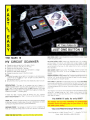
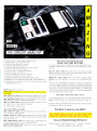
ON SCANNERS
$250.00
$15.00 PPF1 K...Kit/Plans.. $175.00
Assembled
a
L
By Mark Saxon
CAUTION THESE DEVICES CAN BE HAZARDOUS AND MAY SOON
BE ILLEGAL.
gwC
$,
aV
et
0r
«iheP
\SP.
otde`d c
5a.
e0 d
íP93, y
GPII
0:01
L0ct.,\Ntß0. y2ß.
e2\
ge9.as,91
''
SA
CIRCLE 711 ON FREE INFORMATION CARD
About cops, Portland, MARS, tow trucks,
trains, and other scanner topics!
SCANNER FOLKS KEEP MAKING THE
headlines, although all of the news isn't
that good.
One of the more interesting items to
recently show up tells of "Junior" Bel lomy of Muncie, IN. This guy's an enthusiastic scanner user and keeps his scanner
tuned in on the pulse of his community.
While monitoring his local police frequency he overheard a national police
bulletin issued by the police in Madeira
Beach, FL. They were looking for an auto
theft suspect who was also wanted for
questioning in a murder.
Bellomy thought the suspect's name
had a familiar ring, it was a name that was
identical to that of his 20 year old nephew
who was visiting Muncie from Florida.
Bellomy drove over to the Muncie PD
station house and asked the Captain if it
was his nephew that they were seeking.
After hearing Bellomy's description, the
police agreed that it was, indeed, just the
man they wanted.
What could be easier -Bellomy told
the Captain that the suspect was "out in
the car." The police promptly arrested the
young man who was being sought by the
Florida agency!
On the darker side of the headlines, a
VHF enthusiast with a powerful transmitter tuned it to a frequency where it didn't
belong a few months ago.
Police in Portland, Oregon, reported
that they were looking for the wiseguy
who spent about an hour deliberately jamming the communications of that city's
Bureau of Emergency Communication.
They knew it was no accident because
the intruder was using rather salty language not normally encountered on the
air. Furthermore, he was identifying his
jamming station as Radio Free Portland.
Luckily, the prankster's antics took
place during a usually quiet period for the
victimized agency: no critical calls were
delayed or lost because of the jamming.
A tip of the Hands -on hat to "Junior"
Bellomy, and a knock in the noggin' to
any and all connected with the operation
of Radio Free Portland; may their antenna
shrivel and truly wither.
Handy Hand -Held
Regency Electronics notes that their
HX -750 scanner is a 6- channel hand -held
unit covering 30 to 50
MHz, 118 to 136 MHz,
146 to 174 MHz and 450
to 512 MHz.
Individual channel
lock -out switches temporarily skip over unwanted channels. LED's
indicate which channel is
being monitored. The
HX -750 comes with an
AC adapter /charger, a
rugged flexible rubberized antenna and a
wire antenna. A built -in
speaker is provided, but
you can plug in an earphone.
CIRCLE 742 ON
FREE INFORMATION CARD
Operation is by means of four AA batteries; it can also run from its external 6volts DC, plug -in power pack.
The HX -750 uses plug -in crystals;
that's why, at a suggested list price of only
$159.95, Regency can offer so much for
such a reasonable tab. A keyboard -programmable receiver offering less frequency coverage than the HX -750 would cost
about twice as much! Nice going, Regency!
See the HX -750 at your nearest Regency dealer.
Want To Monitor MARS?
It's not too difficult to hear MARS on
your scanner. No, not the red planet with
all of the imaginary canals. This MARS is
the Military Affiliate Radio System, an
emergency communications system run
by volunteer operators who are usually
licensed Hams. MARS comes in three
different versions, Army, Navy and Air
Force, and the frequencies used span the
entire shortwave and scanner spectrum
with Voice, CW, and RTTY traffic.
Army MARS stations appear to be especially plentiful and they offer much
good listening. On the VHF low band,
look for these stations on 40.95, 46.79,
49.79 and 49.93 MHz.
When it comes to the high band, check
out 143.415, 143.99, 148.65, and 150.625
CABLE -TV
MHz. Frequency 143.99 MHz is a rather
active repeater output frequency (the talk in frequency is 148.01 MHz).
Hooked On Hooks
This time of the year there's plenty of
activity on the channels used by those
commercially engaged in relieving auto
emergencies. The action primarily consists of dispatching tow trucks ( "hooks,"
as they are called in the trade) to the scenes of dramatic accidents or simple vehicle
failures from "natural causes" (like overheating, broken axles, failed brakes,
etc.).
Reader Willis Jones of Terre Haute, IN
(there's a 50 -cent bet riding on whether or
not anybody's ever called him "Indiana
Jones ") says that he'd give anything to
find out what frequencies are normally
used by the tow trucks. Well, Indy
err,
I mean, Willis, we'll gladly take that nifty
ark in exchange for that information, but
if you've already disposed of it then keep
us in mind next time!
We like to seek out these dispatches and
operations on 150.815, 150.83, 150.845,
150.86, 150.875 and 150.89 MHz. Auto
clubs offering such services to their respective members normally operate on
-,
150.905, 150.92, 150.935, 150.95,
150.965, 452.525, 452.55, 452.575 and
452.60 MHz. It's a good bet to tune those
frequencies when the weather changes
from bad to terrible; snow storms, sudden
down pours, rapid freezing, and the like.
Here's a bit of scanner-related trivia
connected with tow trucks. In many metro
areas, some of the hook owners are just a
shade on the unscrupulous side and ride
around in their vehicles monitoring scanners tuned to the above listed frequencies.
When they hear a report intended for another hook, they try to rush to the scene
first and beat out the hook for which the
message was intended! The scanners used
for that type of monitoring are usually
hand -held portables, and such a device is
commonly known in the trade as a
"mouse" (because of its appearance with
the whip antenna).
Leo Farnsworth of Texas has a gripe.
Seeking to obtain several needed scanner
frequencies, he reports that he went to the
local outlet of an electronics chain store
and picked up a frequency directory
promising all manner of frequencies including railroad and aircraft listed. Sez
Leo, when he got it home he realized that
the book was a sheep in wolf's clothing,
having only very sparse and spotty
coverage in all areas rather than the indepth.coverage implied.
The two frequencies he wanted most
were those of the Texas State Railroad
Commission and also NASA's aeronautical operations in El Paso. Leo wrote
(Continued on page 18)
11,111M-..
sl
WE'LL
BEAT ANYONE'S
R ICES!
PRICES!
WHOLESALE
MATCH OR
ÉTAIL
7
BONANZA!
ADVERTISED
SINGLE
ITEM
10 -UNITT
PRICE
PRICE
RCA 36 CHANNEL CONVERTER (CH. 3 OUTPUT ONLY)
29.95
18.00 ea.
PIONEER WIRELESS CONVERTER (OUR BEST BUY)
88.95
72.00 ea.
LCC -58 WIRELESS CONVERTER
76.00 ea.
92.95
JERROLD 450 WIRELESS CONVERTER (CH. 3 OUTPUT ONLY)
105.95
90.00 ea.
SB ADD -ON UNIT
109.95
58.00 ea.
BRAND NEW
TRIMODE UNIT FOR JERROLDS
Call for specifics
MINICODE (N -12)
109.95
58.00 ea.
MINICODE (N -12) VARISYNC
119.95
62.00 ea.
MINICODE VARISYNC W /AUTO ON -OFF
179.95
115.00 ea.
M -35 B (CH. 3 OUTPUT ONLY)
139.95
70.00 ea.
M -35 B W /AUTO ON -OFF (CALL FOR AVAILABILITY)
199.95
125.00 ea.
MLD- 1200 -3 (CALL IF CH. 2 OUTPUT)
109.95
58.00 ea.
INTERFERENCE FILTERS
CH. 3
24.95
14.00 ea.
JERROLD 400 OR 450 REMOTE CONTROLLER
29.95
18.00 ea.
ZENITH SSAVI CABLE READY (DEALER PRICE BASED ON 5 UNITS)
225.00
185.00 ea.
SPECIFY CHANNEL 2 or 3 OUTPUT
Other products available Please Call
-
-
-
Quantity
Output
Channel
Item
TOTAL
PRICE
Each
SUBTOTAL
California Penal Code #593 -0 forbids us
from shipping any cable descrambling unit
to anyone residing in the state of California.
Shipping Add.
$3.00 per unit
COD & Credit
Cards -- Add 5%
TOTAL
Prices subject to change without noticePI
Price
FASF PRINT
Name
Address
City
State
'
Phone Number
Zip
Cashier's Check
C;
Money Order
Acct #
E COO
(
I
E Visa
IT
Mastercard
Exp. Date
Signature
FOR OUR RECORDS:
DECLARATION OF AUTHORIZED USE
I, the undersigned, do hereby declare under
penalty of perjury that all products purchased, now and in the future, will only be used on cable
TV systems with proper authorization from local officials or cable company officials in
accordance with all applicable federal and state laws.
-
Dated:
-. _
-
_
Signed
Pacific Cable Company, Inc.
73251/2 RESEDA BLVD., DEPT.
(818) 716 -5914
#_
RESEDA, CA 91335
Calls (818) 716 -5140
No Collect
IMPORTANT: WHEN CALLING FOR INFORMATION
Please have the make and model # of the equipment used in your area. Thank You
17
tains an impurity called copper oxide,
which forms barriers between the copper
crystals, making distortion and signal loss
even worse.
Linear-crystal/oxygen -free copper cables are made only by Hitachi Cable, Ltd
(U.S. patent pending). The LC -OFC cable is available for a wide variety of audio
and video applications (at prices starting
at $28.00 for a pair for stereo interconnecting cables and $2.50 per foot for
New Products Showcase
Continued from page 8)
they developed a technique that produces
oversize copper crystals called, logically
enough, "giant crystals." Then they de-
(
vised a copper extrusion process that
stretches the giant crystals until they are
thousands of times longer than usually
made.
LC -OFC cable also makes use of a
purer grade of copper, known as oxygen free copper (OFC). Ordinary copper (like
the kind used in so- called "monster" cables that are currently on the market), con-
speaker cable) through audio/highfidelity outlets throughout North America.
Get every issue!
understanding of computer electronics
while you're building those enjoyable
projects. As an added bonus, this how to book gives you detailed instructions
for doing those projects with the TS
2068, 1500, and 100 computers.
Jim Stephens is an educator and a
devoted electronics hobbyist. A
resident of Nashville, Tennessee, he
has worked with the Tennessee
Department of Education for the past
ten years. Stephens constructed his
own microcomputer in 1978 and has
published numerous articles in such
popular magazines as
Microcomputing, Sync, Timex/Sinclair
YOU CAN HAVE THE NEXT SIX ISSUES of
your home for only $14.00. We pay the postage.
If you want the next twelve issues, you can even
save two dollars off the newsstand price. Get
twelve issues for $28.00
miss any future issues of Hands -on Elec-
tronics-SUBSCRIPTIONS
ARE NOW AVAILABLE!
EVERY ISSUE OF Hands -on Electronics
will continue to contain a variety of construction
articles to suit every taste. In addition, feature
articles on electronics fundamentals, test equipment and tools will round out each issue, Of
course, Hands -on Electronics will continue to
provide new product and literature listings to
keep you up to date on the latest developments
in electronic technology.
GET IN ON THE ACTION! Order your next
issue of Hands -on Electronics today. Use the
convenient order coupon below. Be sure to send
check or money order -no cash!
User, Radio- Electronics, and Run
Magazine.
Scott, Foresman and Company,
1900 East Lake Avenue, Glenview, IL
60025. Paperback, 228 pages, $12.95.
Saxon on Scanners
(Continued from page 17)
to us for help and we, in turn, looked up
the wanted frequencies in several reference guides in our own library, Rail Scan
Hands -on Electronics SUBSCRIPTION
want to be sure don't miss any issues. Send me the next six issues of Hands-on Electronics for
$14.00. Postage is free in U.S. For Canada add $3.00. Foreign add $7.00
want to be sure I don't miss any issues and want to save $2.00 too. Send me the next twelve
issues of Hands -on Electronics for $28.00. Postage is free in U.S. For Canada add $6.00. Foreign
I
I
I
add $14.00.
Allow 6 -8 weeks for the first issue to arrive.
Please print
Detach and mail today to:
HANDS -ON ELECTRONICS
SUBSCRIPTION DEPT.
P.O. BOX 338
MOUNT MORRIS, IL 61054
(Name)
(Street Address)
L
18
(City)
(State)
(Zip)
Information Systems; AS, Electronics
Technology; BS, Computer Information
Systems; BS, Computer Technology;
and BS, Electronics Technology. The
degrees may be earned through a wide
variety of methods.
M.S., Springfield, OH
One reader called to tell us that she is
enrolled in a Cleveland Institute of Technology (CIE) course that will reward her
with an Associate in Applied Science
Degree in Electronics Engineering Technology when completed.
(Continued from page 15)
Hands -on Electronics delivered directly to
TO HELP YOU TO BE SURE that you don't
(Continued from page 5)
York offers a variety of associate and
bachelor's degrees through its Regents
College. Those include: AS, Computer
Bookshelf
SUBSCRIBE
TODAY!
Use the order
form below.
IF YOU'RE THE KIND OF READER that
doesn't want to wait, you can order your next
copy of Hands -on Electronics now. Hands -on
Electronics is crammed full of electronic projects that you won't be able to wait to build for
yourself. You can expect top -notch digital projects, fun -to -play electronic games, valuable
add -on computer projects, BCB and shortwave
receivers, photographic darkroom gadgets, devices to improve your car's performance, test
equipment ideas. and more in every issue of
Hands -on Electronics.
Letters
AHOA6
J
and Air Scan.
The Texas State Railroad Commission
operates on 39.94 MHz; NASA in El Paso
is on 121.75 MHz. Long ago we realized
that some of the frequency directories offered by chain stores were satisfactory for
beginners and those with a very casual or
passing interest in scanners, but those references were a waste of time and money
for hobbyists pursuing scanner use on a
serious level.
For directories oriented more towards
the serious scanner user, request a free
catalog from CRB Research, P.O. Box 56GP, Commack, NY 11725. They publish
the Rail Scan and Air Scan directories
mentioned above and also offer many
other books and guides for scanner and
shortwave enthusiasts.
Tune you in next time around!
WITH CIE,
THE WORLD OF ELECTRONICS
CAN BE YOUR WORLD, T00.
Look at the world as it was 20
years ago and as it is today.
Now, try to name another
field that's grown faster in
those 20 years than electronics. Everywhere you look,
you'll find electronics in
action. In industry, aerospace,
business, medicine, science,
START WHERE YOU
WANT, GO AS FAR AS
YOU WANT.
CIE's broad range of entry,
intermediate, and advanced
level courses in a variety of
career areas gives you many
options. Start with the Career
Course that best suits your
talents and interests and go as
far as you want -all the way,
if you wish, to your Associate in
Applied Science Degree in Electronics Engineering Technology. But
wherever you start, the time to start is
now. Simply use the coupon below to
send for your FREE CIE catalog and
complete package of career information.
Or phone us at 1-800-321-2155
(in Ohio, l- 800 -362 -2105). Don't wait,
ask for your free catalog now. After all,
there's a whole world of electronics out
there waiting for you.
government, communications
-you name it. And as high
technology grows, electronics will
grow. Which means few other fields,
if any, offer more career opportunities,
more job security, more room for advancement-if you have the right skills.
SPECIALISTS NEED
SPECIALIZED TRAINING.
It stands to reason that you learn
INDEPENDENT STUDY
BACKED BY PERSONAL
ATTENTION.
anything best from a specialist, and CIE
is the largest independent home study
school specializing exclusively in
electronics, with a record that speaks for
itself. According to a recent survey, 92%
of CIE graduates are employed in
electronics or a closely related field.
When you're investing your time and
money, you deserve results like that.
independent study
because it puts you in a classroom of
one. So you can study where and when
you want. At your pace, not somebody
else's. And with over 50 years of
experience, we've developed proven
programs to give you the support such
study demands. Programs that give you
the theory you need backed with practical experience using some of the most
sophisticated electronics tools available
anywhere, including our Microprocessor
Training Laboratory with 4K of random
access memory. Of course, if you ever
have a question or problem, our
instructors are only a phone call away.
We believe in
F
I
I
I
MIMEO
EN'
Cleveland Institute of
Electronics, Inc.
1776 East 17th Street
Cleveland, Ohio 44114
216 -781 -9400
A half century teaching electronics.
M
M
O
M
M
M
-I
lECleveland
MIMI
Institute of Electronics,
1776 East 17th
Inc.
Street, Cleveland, Ohio 44114
YES...I want to learn from the specialists in electronics -CIE. Please send me my FREE
CIE school catalog, including details about CIE's Associate Degree program, plus my
FREE package of home study information.
Print Name
Address
City
Age
State
Area Code /Phone No.
Check box for G.I. Bill bulletin on educational benefits:
MAIL TODAY!
Zip
Veteran
ElActive Duty
RP
r ELECTRONIC
LCOMPONENTS
By Don Jensen
ON DX'INC
Listen to the lands of the tango,
cumbia, mariachi, and huayno
IN THE PAST FEW COLUMNS,
MANUFACTURERS OF QUALITY
ELECTRONIC COMPONENTS
BATTERY CLIPS
DISPLAYS
&
HOLDERS
CONNECTORS
CABLE SETS
CAPACITORS
JACKS
FUSES
LEDs
IL
PLUGS
POTENTIOMETERS
LAMPS
KNOBS
RESISTORS
RELAYS
RF COILS
SPEAKERS
SEMICONDUCTORS
SWITCHES
TEST
EQUIPMENT
TRANSFORMERS
WIRE
A
TOOLS
CABLE
OVER 15,000 DIFFERENT ITEMS IN STOCK!
Salar end Order Dark
(PST)
Open Iron 6.00a
.
TRIMS
COD.
S,so.
Maae.Cha
(Open
A
sse
«ousts ...wettable)
Phan and Mad
Orders Welcome
Cantons Mailed
Outside USA
Send $2.00
MOUSER ELECTRONICS
W00DSIDE AVE.. SANTEE. CA 92071'
PHONE (619) 449-2222 TWA 910 - 331 -1175
11433
CIRCLE 714 ON FREE INFORMATION CARD
Get
professional
quality at home.
SAYING
KeproClad is the quick, easy and inexpensive approach to home production of
quality printed circuit boards. Minimum
investment required.
Complete package.
packaged-pre-sensitized negative acting
dry film photoresist.
Extremely rugged
yet holds fine lines.
Available in two sizes with one or two sided copper foil. Developer included.
For your local distributor write or call:
ing.
Also, the majority -but no means
all-of those
Latin voices operate on the
so- called Tropical Bands; the SW chan(Continued on page 102)
GOOD -BY TO
OLD
FRIENDS
HCJB
CLAYTON
HOWARD
HELEN
HOWARD
l-314-343-1630 (in Missouri)
Kepro Circuit Systems. Inc.
630 Axminlster Drive, Fenton, MO 63026 -2992
22
Dutch, respectively, are the predominant
tongues. Many native-born citizens of the
southern tier of South American countries
have German, Italian, even Japanese as
their first language. Additionally, there
are many who speak the various Indiar
and Creole languages.
SWL's soon find that there is no single
type of music typical of Latin America.
The Argentine tango, the Colombian
cumbia, the Mexican Mariachi, the Peruvian huayno-they're no more alike then
Mozart and Madonna!
What that all means is that when it
comes to listening to the shortwave stations of Central and South America, and
their off-shore islands, there is a tremendous variety of programming awaiting
you.
Unfortunately, beginning shortwave
listeners tend to shy away from those stations. There are hundreds of Latin stations
on the bands, but compared to most of the
powerhouse broadcasters of Europe and
Asia, most are relatively low powered.
Signals, typically, aren't as big and boom-
1
KeproClad comes
1.800- 325 -3878
WE'VE
taken an overview of the world, continent
by continent, looking at the different
countries and their shortwave stations.
This time we complete the global
junket by turning our eyes -make that
ears!-toward Latin America.
Shortwave listeners, like other nor teamericanos, tend to think of Latin
America as being right next door. But like
many other of our perceptions of the
world, that is only partly correct.
Certainly, Mexico, Cuba, and the Central American nations are our southern
neighbors. But Latin America also includes countries such as Argentina, Brazil, and Chile -far more distant than we
may realize.
New York, for instance, is closer to
Moscow than it is to Rio de Janeiro. From
San Francisco it's about 5,000 miles to
Tokyo, but nearly 6,000 to Santiago,
Chile. A beeline from Chicago to Istanbul
is shorter than one between the Windy
City and Buenos Aires!
In the common stereotype, a Latin
country is purely Spanish in language and
flavor. But in fact, Brazil, the largest
South American country, is Portuguese speaking; and in French Guiana, Guyana,
and Surinam, French, English, and
CIRCLE 713 ON FREE INFORMATION CARD
Helen and Clayton Howard sent this farewell card to many of their
listeners when they retired from the staff of HCJB in Quito, Ecuador,
in 1984. Clayton served the station for 43 years. Both Howards were
familiar to listeners as hosts of the popular "DX Party Line" program.
can]
Jar uary-February
12.86
CRIBBAGE BOARD
The Digital Cribbage Board may not improve your game, but it will
make scorekeeping quicker and a lot mere fun than a board and pegs!
IN THE CARO GAME
CALL-7.-D
CRIBBAGE,
sccrekeeping requires a counter (sco
keeper) that lot only tal ies total purls,
bu: also shows the point count of the last
Dlay entered. Our Digi al Cribbaze
Counter fills those requirerrents and isa
pleasure to ese. Of cou se the winners
sm le and the losers stil say "hurry Lr
and deal," tut the Digital Cribbage
Board verifies to both players that
each entry is correct.
Since the scorekeepet s composed of two identical cìcuits to
accommodate two players, only
one circuit is shown s:.hematically in Fig. 1. However,
keep in mind that two suci circu ts are needed and are ar-
raiged side-by-side
n
opposite
dnections on the printec-circuit foil pat:err.
Wen the board is placed between too copcsing players, each play- has one haf
(turn page,
Photo by Wai-er Herstatt
4
of the board facing him while he is still able to view his
opponent's score on the other half.
Each circuit is composed of two separate counters with the
score count being fed into both. One counter, a two -digit unit
capable of counting to ninety nine, registers play points. That
counter, which resets to zero before entering each new play,
displays the last play count entered. The other, a three -digit
counter, counts to one hundred and ninety-nine, and is reset
only at the start of a new game. The second counter shows
total points for all points entered during the game.
With low cost in mind, the circuit was constructed of all
CMOS integrated circuits (IC's). Inexpensive computer -type
keyboard switches were used for the COUNT, PLAN
CLEAR, and game RESET controls. The controls and
readouts were mounted directly on the circuit board
for simplicity, but could easily be remotely located
by wiring between components and board. The
readouts are modulated with a 50% duty cycle
squarewave to reduce the current drain of the readouts to a level that makes battery operation feasible.
The Circuit
The input pulses from the count pushbutton switch, Si, are
conditioned by a debounce circuit consisting of U6 -d (% of a
hex Schmitt trigger) and fed to the pin 9 inputs of two
CD4518 dual up- counters, U2 and U8. Both U2 and U8 are
configured so that one of its internal counters counts units
while the other serves as a decade (tens) counter. After a
count of ten, the units counters of U8 and U2 feed one pulse
into their respective decade counters via AND gates U5 -a and
+6V
U5 -c.
DIS1
16
10052
16
13
7
3
DIS5
1
12
13
2
14
6
U9
11
Nosh
CD4511
'
13
10
3
CC
df
1M
14
11
CC
9
R13
U8
8L6V0
1/4
10
2
DUAL
=
CD4081
3
DIS4
16
7
a
7
7
13
15
12
2
U7
6
CD4511
13
eb
DECODER'
DRIVER
U5 -b
I
d
I
e'
f
CC
3
11
7
1/4
CD4081
R20
8
U6-c
1
0
6
DIS3
+6V
o
CD4584
R21
--
3
13
R
U4 -a
S3
that share only one common
component, C4; therefore, only
one -half of the circuit is shown.
The circuit's low power, CMOS
construction makes battery
operation practical.
R5
3
Q1
+6V
O
1
=
16
t
DIS2
=
13
CD4511
14
DECODER/
DRIVER
1/6 CD4554
220K
U5-c
DUAL
UP- COUNTER
8
16
13
.05
12
1
5
2
6
15
.05
7
e
il
U1
11
CD4511
10
9
14
,3
DIS1
R30
VN
10
1hh
8
a
b
d
M
A
144
V 1ti
2
11
CC
g
R36
o
RESET
S2
C
d'
9
15
C3
10
10
0+6VI4
DECODER/
DRIVER
O
13
R29
3
4
o
.-.
14
CD4081
C 04518
C2
...
1/4
U2
0
11
R23
15
U6-cl
R3
COUNT
Si
U3
2
2
C4
100
12
13
2.2K
2.2K
13
12
R6
CC
R2
16
11
2
C
2N3903
+6v
O
+6V
22
CD4013
D -TYPE
FLIP -FLOP
2.2 K
START
Fig. 1 -The Digital Cribbage Board
is made up two identical circuits
/0
-WV--
14
GAME
U6
R4
1
2.2K
U6-a
i
6
e
-
CD4584
1/6804584
3
24
14
CC
9
11
4
a:
1
d
14
US-a
9
e'
DECODER/
DRIVER
8
9
V4/.
ib
f
a
12
UP- COUNTER
DIS 5
R7
11
CD4518
-
HP5062-7653
R7-R36
U6
1'6 C04584
2 -Foil pattern for the
Digital Cribbage Board's
printed circuit is shown
full -scale. Note that if the
pattern were cut down
the center, you'd have
two identical circuit board patterns.
Fig.
The counter circuit that's made up of U2 and the decoder/
driver chips UI and U3 constitute the two digit PLAY counter.
Pushbutton switch S2 clears the play counter before entering
each new play count. The counter circuit comprised of U8
along with decoder/drivers U7 and U9 and flip -flop U4 make
up the three -digit total point counter. The flip -clop was used
instead of another counter to indicate one hundred. The
output of U4 is coupled to Ql, which acts as a driver for the
two segments used to indicate the number "1" on DIS3.
Pushbutton switch S3 clears counter U8 and resets flip-flop
U4 to start a new game.
The inverting Schmitt triggers, U6-a and U6 -b, make up a
squarewave generator with a 50% duty cycle. The output of
that generator is coupled through U6 -e to the blanking inputs
of U I and U3. The generator output is also fed to the blanking
inputs of U7 and U9 through U6 -f. That squarewave signal
PARTS LIST FOR DIGITAL CRIBBAGE BOARD
SEMICONDUCTORS
DIS1 DIS5 -HP- 5082 -7653,
7- segment, common -
cathode display (Jameco Electronics)
Q1- 2N3903 NPN silicon bipolar transistoU1. U3, U7, U9- CD4511 BCD to 7- segment decoder.
driver, integrated circuit
U2, U8-CD4518 dual up- counter, integrated circuit
U4- CD4013 dual D -type flip-flop, integrated circuit
U5- CD4081 quad two -input NAND gate, integrated circuit
U6- CD4084 hex Schmitt trigger, integrated circuit
RESISTORS
(All resistors are '%4 watt, 5% units)
R1- 100,000 -ohm
R2, R4 R6 2200 -ohm
R3-220,000-ohm
R7R36-100 -ohm
CAPACITORS
C1- 0.02 -µF, 25 -WVDC, electrolytic
C2. C3- 0.05 -µF, 25 -WVDC, electrolytic
C4- 100 -p.F, 16-WVDC, electrolytic
ADDITIONAL PARTS AND MATERIALS
S1 S3- Normally open pushbutton switch
NOTE: Two of each semiconducting, resistive, and capacitive components listed above, except C4 (only one
required), are needed to assemble the project.
Printed -circuit material, 4 C- or D -cell batteries and holder; or 6 -volt, 200 -mA plug -in wall power supply, enclosure, wire, solder, hardware. etc.
The Digital Cribbage Board's printed- circuit board, part
No. CR -7, is available from Electronics Enterprises
(priced at $14.95, plus $1.50 for postage and handling),
3305 Pesanta Way, Livermore, CA 94550. Please allow
6 to 8 weeks for delivery.
25
RB-
-Rf9-
-R13-
DIS5
DIS4
LILIS3
-J-
--R10R9-
IJ
-R22-
- R21-R18-R17-
RÌ5
-J-
R11-
-v-
l
1
D J
-R2--J- s-
III
J
J
I
J
U4
...
not mirrored in each half
of the circuit is C4, which
is a filter that is common
R3
to both halves. The
dashed lines indicate
I
DIS2
ri
9n
f
1
-J-
U1
-R26-
6n
-J-
I
I£3
S2
Y310 a1100
TOTAL POINTS
I
I
tR4
*
-J -
-J -
i
1
1
r
-r---r-Z18-
8n
-OZH-
-918-
-Ltd -918-
-018-
I
C2
1
-R25--
J
i
I
- R29 -
U2
1
f
II
-R27-
-R34-
1
r
C4
- R28DIS1
I
CH
-OCR-
-9H-
R1
-R23-R24-
- R32 -
-IEH-
-5£H-
-R6-
-R30-R35-R31-R36-
-R33-
jumper connections that
are located under components.
ISIU
-£EHZSH-9£H-
Cl
U6
.N!
only component that's
asea
-szH-
I
1
U5
}
1
;
{
T
-t£H-
-8ZH-
II
J
r
r-
-sza-
1
f1
l
r
-r-
-9ZH-LZa-5z8-
U9
1
J
J
.._
01
I
U8
f
zn
I
J
U7
I
{
En
I
r
Fig. 3 -The parts layout
for the Digital Cribbage
Board shows that two
matching circuit boards
make up the entire project. Component designations are duplicated in
each half. That means
that two ill's, two U2's,
and so on are needed to
complete the project. The
Iir
C31
-R12-
-R 16-R20-
tRZ
ZS
ski
-r-
-r --
I
I
Es
-R7-
-R14-
S3
-6H-£18-
-LH-
SSI0
ES10
-88-
+6v
cND
modulates the seven-segment readouts, reducing the current
drain of the readouts by about 50 %. Display DIS3 was not
modulated because it only illuminates two segments on
counts over one hundred.
Construction
Ald
PLAY
INIOd
COUNT CLEAR RESET
4111
II
101
In order to lay out the circuit on a single -sided printed circuit board, many wire jumpers were used. Double -sided
board with plated- through holes would simplify and speed
construction, but the cost of double -sided boards make wire
jumpers more economically desirable. You may make your
own board from the foil pattern shown in Fig. 2, or purchase
the etched, tinned, and drilled board from the supplier given
in the Parts List.
Figure 3 gives the location of the components on the
printed- circuit board. Note that the layout is divided in half
by a dashed line. Each half is identical; therefore, component
designations are duplicated on each half of the board and that
condition is reflected in the Parts List, where the parts given
are only for half the board. When purchasing the components, all except C4 (a 100 -11F unit common to both circuits
and located at the center dividing line of the board) are
multiplied by two. In other words, two Ul's, two U2's, and so
plastic about 1/2-inch thick covers the PC board. Hole=
are drilled to align with the pushbuttons and white lettering added
A piece of red
26
TABLE 1
CRIBBAGE SCORING COMBINATIONS AND TERMS
Card Values
Ace
2
1
2
3
3
4
4
5
6
5
6
7
7
8
8
9
9
10
J
10
10
Q
10
K
10
Scoring Combinations
Term
Meaning
Pegs
Pair
Pair Royal
Double Pair
Royal
Two cards of the same rank
Three cards of the same rank
Four cards of the same rank
2
6
12
Run
Flush
Three or more cards in sequence
Three or more cards of the same
suit
Any two or more cards totaling 15
(i.e.: 5-Q, 7 -8, A -8 -6, etc.)
To non -dealer in five -card game
only
To dealer only if Jack is turned up
For holding Jack of the same suit
as the starting card
For playing last card toward 31
If exactly 31
Fifteen
For Last
His Heels
His Nob
Go
1
1
/card
/card
2
3
2
1
1
2
on. When populating the board, do one side, then flip the
board around and do the other.
Start construction by mounting and soldering all the resistors. Clip off the excess resistor leads, but do not throw
them away. Those short lengths of leads provide an adequate
supply of wire jumpers. Next, make all the jumper connections; some of them, those indicated by dashed lines, are
located under components DIS4, U2, U4, U6, U7, U9, and
Si. After all the jumpers are in place, mount the balance of
the components.
As always, exercise care when handling the CMOS chips
to prevent electrostatic damage to the components. Pins 3 and
6 of DIS1, and pins 9 and 14 of DIS2 were clipped off. Those
pins are not used and eliminating them simplifies the circuit board layout.
The power supply chosen will depend on whether a "carry
around" portable or an AC- powered device is desired. The
power supply chosen, which should output 6 volts with a
current of at least 150 milliamperes, will dictate the final
enclosure size. Four C- or D -type cells can furnish adequate
power for a portable model. Or a small plug -in wall power
supply can be used to power the circuit from any 117 -VAC
outlet. A third option would be using rechargeable batteries
and a charging supply (several of which have been presented
in past issues of Hands -on Electronics and Radio Elec-
tronics).
When your Digital Cribbage Board is complete, and you
sit down across the table from your opponent, you will
definitely find that keeping score is effortless, faster, and a lot
more fun than the conventional Cribbage board and pegs.
You may still lose the game -sorry to say, we still haven't
figured out how to make every one a winner. But, at least the
circuit helps to cut down on the problem of scorekeeping.
GETTING INTO CRIBBAGE
The game of Cribbage, which dates back to about the
17th century, has several variations -five card, six card,
and sewn card. However, we will only concern ourselves
with th- most basic form, five -card. Table gives the the
scoring combinations and terms used in the game. Cribbage is usually played to 61 points or pegs (but may also be
played _0 121); the first player to reach that figure wins. If,
when cne player reaches that score, the other has not yet
scored 31 or more (91 when the winning score is 121), he is
said tobe in the lurch or simply lurched. A more colorful
word used is skunked!
Play starts by determining which player gets first deal
by a cat of the cards; low card deals first (Ace being the
lowest, Either player may shuffle, but the dealer must
shuffle Iast. Five cards, one at a time, are dealt to each
player face down; the first going to the non- dealer. The
non -dealer immediately pegs (advances his peg on the
scoreboard unique to Cribbage) three for last-but only
on the first deal of a new game. If he fails to do so before
the play begins, he loses those pegs. Each player then
discards two cards face down, forming a crib of four. The
crib b-longs to the dealer at the end of that deal, and any
scoring combinations that are found in the crib are added
to the dealers point tally. Thus, in his own interest, the
non -staler attempts to discard the least combinable cards
that hr can imagine.
In addition, there is aplay -off in which each player lays
down a card and announces cumulative total of the cards
played. First, the non -dealer cuts the cards and the dealer
turns up the first card of the bottom half of the deck, let's
say a deuce. Then, the first player lays down a card,
perhaps a 3 and announces. The game continues with the
next player discarding another card, let's say a 10 this time,
announcing 15 for 2 (he then pegs to holes), and so on to a
total 3f 31 points or less. Points are scored for making a
total of 15 and 31, for the last play without exceeding 31,
and fur any scoring combinations that may be made between both players' cards along the way. Finally, the non dealer scores for combinations contained in his own cards.
And the dealer scores for his own cards as well as those
contained within the crib.
What we've attempted to do here is give some of the
most basic rules of Cribbage. For a better under standing
of the game, you might want to pick up a copy of The
Pend uin. Book of Card Garnes by David Parlett (published
by Panguin Books).
1
4111V
13S38 I:lY310 iNn4J
TOTAL POINTS
PLAY
AHld
S1NIOd 1t11O1
COUNT CLEAR RESET
The author's prototype is housed in a simple wooden enclosure,
without an internal power supply. Instead, the author opted
to use a wall-mounted power supply like those used for
TV-games and calculators.
27
r
Electronics Paperback Books
NEW OFFERINGS AT SPECIAL INTRODUCTORY PRICES
\
I
,.r »
aen,
,e
C, a
rxprr
A4iq 4
tbr
Linear IC
Epolvelents
and Pin
Connections
rarrya
WRITE ZX SPECTRAM GAMES PROReg Price
GRAMS
i7l00. Ste ONLY
$5.00. Step -b ow
grade snows how to write
$5 0nics games
7
.y
l'
INTO THE QL ARCHIVE ..... Reg Price
low
NOW ONLY
How you can use this
database program sup
plied with the Sinclair OL
PROGRAM ART
SPECTHE
MING THE
TRUM ,.... Reg Price
IRO. Deng
56.25. Using BASIC td
make your Spectrum do
clever things.
20 PROGRAMS FOR
SPECTRUM 816K
Reg Price
ZXBI
NOW ONLY
$4,00. Programs with
charts. Card games.
Battleships, Calendar.
Z%
$rlK
and more.
LINEAR IC
ALERTS AND PIN
ELECTRONIC PROJECTS USING SOLAR
Price
CELLS ..... R
NOW ONLY
$4.00. Simple circuits
powered by the energy of
the sun
}WO.
NOW ONLY
$3.75. Includes 2 -tone
Door Buzzer. Auto Porch
Light, Lamp Dimmer, and
}BR
CONNECTIONS .....
512.50 (shipping
247 pages. 7 *
shows bons and pin
connections for popular
user oriented IC's
ONLY $4.00. Three Dawn.
sections Switch actr
Infrared 8
eared nit
ultrasonic systems.
smoke. gas, water deter
;
iron
more
-
Reg}r4
NOW 53.50.
ELECTRONIC GAMES.
NOW 54.00.
- BUILD SW RADIO RCVRS. Reg
NOW $3.25.
SO LED CIRCUITS, Bk 2. Reg
NOW 54.00.
INTRO TO 6502 MACHINE CODE. Reg
y.ti,
OFFER GOOD TILL FEBRUARY 28, 1986
AS Simple
Computer
t. onteramming
ELECTRONIC SECURITY DEVICES
Reg PricelrK NOW
9tIC
!Mt
sn
INTRODUCTION TO
VIDEO ..... Reg Price
NOW ONLY
00. For the person
who has lust or is about
to buy a video recorder.
ELECTRONIC
HOUSEHOLD PROJECTS ..... Reg Price
Alt,
NOW $5.50.
THE PRE-BASIC BOOK. Reg
BUILD TREASURE LOCATORS. Reg.7!A NOW $4.00.
NOW $4.50.
AUDIO AMPLIFIER CONSTRUCTION. Reg
AUDIO PROJECTS. Reg W.A,NOW $4.00.
eox,M,i,.xrr
I
ter
$5 Simpler
Amateur Sand
Amateur Buna
re.mmo Par
Aerials
ExpinineE
Aerie.
MO 90e xrt
.
INTRO TO PRO
SECRETS OF THE
COMMODORE 64......
$5.00. Masses of useful
$5.00.
600./800 XL
Perfect complement to
the Atari users manual.
Even shows how to use
animated graphics
into and programming
tips not found in any
user's manual
-
-
-
GRABBING THE ATARI
ANTENNA PROJECTS ..... 55,00.
Practical radio antenna
designs that deliver good
performance and are rele y simple
inexpensive to build.
WHITE'S RADIO
LOG
$4.94. An up.lo.
dale directory of AM. FM
and TV stations.Including a section on world w m. sex
-e stations
ING CIRCUITS
$5.00. Practical
add -ons transform your
Computer Into control or
measurement equipment
2
optical sensors. motor
Controllers, and more.
tale et
Dome. *ea
Yaw Ow, Pott sS.
ate
YwNYe
Eleetreep
b
Latest into on usual and
exotic shortwave broadcast stations
SIMPLE AMA TEUR BAND
ANTENNAS
55.00.
A,I kinds of antennas for
all kinds of amateur radio
receotion
Quality Paperbacks
ators, temperature and
Were,
CONFIDENTIAL
FREQUENCY LIST, 6th
edition.
$13.95.
IE 25
-BOOK
55.75. Interlacing
sound and speech genes
1
E
i
electronics
T.w
Crystal Set
Constmctioe
Oren.
&mPlieee
eri ntt,c
Pmieeb
INTRODUCTION TO
RADIO DOING
55.00. How to optimize
the reception of distant
short -wave broadcast
and amateur stations.
.
MICRO INTERFAC-
MICRO INTERFAC-
ING CIRCUITS -BOOK
PreìP
INTRO TO Z.BO MA.
CHINE CODE ..... 55.75.
Speed up your programs.
They may be harder to
write, but it's worth learning how. Some demo
programs a,e included.
COMPUTER TECHNOLOGY EXPLAINED
.., 55.00. Explanations
for computer terms often
encountered. A dictionary
for computer lingo.
INTRODUCTION TO
RADIO DOING .....
$5.00. Get into this fan cinating hobby. This book
tells you lust about everyyou need to know
to get started
-
ram
ffi
LONG DISTANCE TV
DOING ..... $5.00. A
practical and auhontative
introduction to this unusual aspect of
electronics
ELECTRONIC SCI ENCE PROJECTS .....
55.75. Simple to corn.
plex. a group of projects
with a strongiy si ienttfic
flavor
HOW TO DESIGN
ELECTRONIC PROJECTS ..... $5.75. How to
use standard circuit elemeets to make custom
electronic projects.
CRYSTAL SET CON STRUCTION ..... $4.50.
A variety of crystal radio
receivers for the exDerimenten and hobbyist
f
sy
Projects
-
ELECTRONIC MU-
SIC AND CREATIVE
TAPE RECORDING .....
55.00. Shows how you
can make electronic music at home with simple
arm eleccensve equip
DESIGN 8 MAKE
YOUR OWN PC
BOARDS ..... $5.75. Everything you need to
before you
for
pnted
your projects
etc
INTERNATIONAL
TRANSISTOR EQUIVALENTS
$7.50,
Locates possible sub.
stitutes for a popular
user-onented selection of
modern transistors JapaEuropean and
Ame.
erican types
MODERN OP -AMP
PROJECTS ..... 55.00.
Includes a Slide Timer.
AF Signal Gen, Mike Preamp, Scratch Filter. and
much more.
Affordable Prices
ól°°tro,hw
IC
COUNTER DRIVER
8 NUMERICAL DISPLAY PROJECTS ...,.
54.50. Numerical indica.
tar devices make it easy
to count. divide and display
ELECTRONIC TIMER
about every application
Required for every ex
penmenter.
SINGLE IC PROJECTS ..... $4.25. Aii
projects In this boo
re
based on one IC anda are
simple to construct Great
way to eel s'a nod wit^, IC s
additional)
PRACTICAL ELECTRONICS
CALCULATIONS AND
FORMULAE ..... $7.50. A
workshop manual that
bridges the gap between
complicated tech theory
and cut and try
Gm/
Book
Total Price of Books
*Shipping
1st two books 500 ea.
kinds to add to the cm
cults from Book 1 of this
series.
1
IC PROJECTS FOR
BEGINNERS..... $5.00.
Written especially for the
less experienced expertmerger Complete pans
layouts and wiring di-
POPULAR ELECTRONIC CIRCUITS.
Book 1 ..... $5.00. More
circutts for hobbyists. Au
dio. radio. test, music,
household and more
agrams.
555 PROJECTS .....
S5.00. So useful that this
IC has an unparalleled
reputation. Here's a book
full of useful applications
_ POPULAR ELECIRONIC CIRCUITS.
I
Book 2 ..... $5.75. More
useful circuits. None at
these projects duplicate
those in Book of this
1
aeries
H01-86
Sales Tax (NY State Residents)
Zip
PRACTICAL ELECTRONIC BUILDING
BLOCKS. Book 2
$5.75. Amplifiers of all
í
L
MICROPROCESSING SYSTEMS ANO
CIRCUITS ..... $7.50.
Guide to the elements of
microprocessmg systems. Teaches all the
fundamentals.
CHECK OFF
THE BOOKS YOU WANT
Name
*Canadian Shipping ($1.50
custom project of your
choice
TRONIC PROJECTS .....
$4.75. A collection of a
wide range of electronic
projects and circuits for
he expeiimente-
Number of books ordered
State
to form almost any
E POPULAR ELEC-
ELECTRONIC TECHNOLOGY TODAY INC.
P.O- Box 240, Massapequa Park, NY 11762 -0240
City
1
*to
El
PROJECTS ..... 55.00.
Timing circuits to lit lust
Propere
for 9epinners
ta
PrpÌac
ELECTRONIC SYSTHESIZER PROJECTS
... $4.50. How to assemble the elements of a
synthesizer and then put
them all together.
PRACTICAL ELECTRONIC BUILDING
BLOCKS. Book
$5.75. Build the blocks
and then combine them
pep4
Carv,teráNrer
to-rip.
Address
IL
HANDBOOK OF IC
EQUIVALENTS AND
SUBSTITUTES .....
55.00. Includes digital
and linear IC's made in
US. Great Britain, Japan,
'.
ElentnonAt
nw,siee.
FIRST BOOK OF DIODE CHARACTERISTICS, EOUIVS, AND
SUBS ..... $5.00, Shows
full Interchangeability
data for Thousands of diodes
HOW TO GET YOUR
ELECTRONIC PROJECTS WORKING
55.00. How to lind the
faultsthem
and get
all them
working.
in
S
U.S. only
($1.00 1st two books, 400 ea additional)
TOTAL ENCLOSED
$
Your guide to everything that's new in electronics, computers and technical
education. Over 400 items. Discover
fascinating kits to build, enjoy and learn
with, as well as assembled high tech products
for home, business and hobby.
r
-1
Heath Company
Dept. 107-374
Benton Harbor, Michigan 49022
MAIL COUPON TODAY and receive the latest
issue of the Heathkit Catalog free of charge
Name
Address
City
CL- 783BR1
A
subsidiary of Zenith Electronics Corporation
IL
CIRCLE 719 ON FREE INFORMATION CARD
State
Zip
J
0w
to Identify
Every IC has its own signature, or DIP-ature. A logical
exploration of characteristics will uncover the chip's
function and help you give it a proper name!
[DONE OF TODAY'S BEST SURPLUS BUYS IS THE LOADED
printed- circuit board. The experimenter can buy a board
containing a dozen or more digital It's and other useful parts
for less than a dollar. Usually the IC's alone are worth several
times the price of the board. Unfortunately.. many of the best
boards are passed up by the hobbyist because the IC's are not
marked with recognizable industry- standard numbers. There
is a solution to the problem of unmarked IC's.
This article describes a way to make TTL, DTL, and even
RTL IC chips sign in once they are removed from the board.
The IC signature shows you which pin is Vcc and which is
ground. The IC signature tells you which pins are probably
output terminals. And it requires nothing more than a piece of
paper and an ohmmeter. After that, a few voltage and current
measurements and you should know what kind of IC you've
got. Here's how it works.
An IC signature is an array of resistance readings derived
from the IC and displayed in an organized way. The x 100
range of an ohmmeter is used. (Be sure that you know which
ohmmeter lead is positive; some ohmmeters change polarity
when switching from volts to ohms especially in the low -ohm
ranges.)
The signature is obtained by recording the resistances
between all terminal pairs of the IC. Use the signature chart
shown in Fig. 1. Connect the ohmmeter's positive lead to pin
1, and move the negative lead sequentially through the remaining pins (3, 4, 5, etc.). Record the measured resistance
across the top row of the signature chart. A resistance measurement of over several hundred thousand ohms does not
convey very much useful information, so there is no need to
record it-put a dash through the box instead.
Move the positive lead to pin 2 and fill in the second row of
the signature chart (Fig. 1) by moving the negative lead to pin
1, 3.4..., etc. Continue in the same manner until every row of
the signature chart is completed. If that is done properly, you
should have as many rows in your chart as there are IC pins.
The steps that follow show how to use the completed
signature to identify your IC.
Step 1
-
Examine the signature chart, that you generated from an
unknown IC, and circle each terminal -to- terminal resistor
you can tell which ones those are because each purely re-
32
sistive connection between two terminals reads approximately the same in both directions.
For the purpose of an explanatory example, refer to Fig, 2
which illustrates a completed signature chart for an unknou n
IC. In Fig. 2 there are twelve circled boxes, six above the
diagonal and six below The circled number in row 5, column
3 has its mirror image on the opposite side of the diagonal in
Row 3, Column 5. The resistance is 7000 ohms in both
directions; therefore, it is a terminal -to- terminal resistance.
That fact is noted to the right of the chart (Fig.2), along with
the other resistance value and identified as Step 1. The remaining terminal pairs show grossly different resistance measurements in opposite directions, indicating the presence of
one or possibly several semiconductor junctions in the path.
It is highly unlikely that a TTL IC, or for that matter any
linear IC, would contain 6 identically valued terminal -toterminal resistances. Maybe the IC is RTL or DTL?
Step 2
Disregard all circled boxes and scan the signature to locate
the row with the lowest resistance readings-Row 4 in this
case. That characteristic uniquely identifies pin 4 as the
substrate connection of the IC or, in other words, the most
negative terminal of the IC.
this
Scan across Row 4 for the lowest uncircled reading
case it is the 750 -ohm reading in Column 11. That distinctiive
reading tells us that pin 11 is the Vcc terminal of the IC.
Record those numbers in the place provided at the right of the
chart -Step 2, Fig. 2.
The other uncircled low-resistance readings in the ground
row usually identify transistor collectors; i.e., output terminals. That is an important clue to be used later.
-in
Step 3
Before proceeding to the identification of other terminals
we measure L. Apply a low voltage, say 3.6 volts (RTL.
supply voltage). to the IC through a milliammeter or multimeter preset to read in the 100-milliampere range. The
positive voltage goes to the Vcc terminal (in this case pin 11)
and the return connects to the IC substrate (in this case pin 4).
To Protect the IC and the equipment, place a 120 -ohm
resistor in series with the current meter. A dead short in the IC
(Continued on page 36,
Q0
VCC
=
By Kenneth H. Reoorr
GND=PM
PM
1CC = PM
NEGATIVE
1
2
3
4
5
6
7
8
9
10
11
12
13
14
15
18
1
2
3
4
5
6
7
10
12
1 -This form is used
to record all resistances
between terminal pairs of
tie unknown IC up to
16 -pins in size. Copy it
on a Xerox machine so
that you'll have a supply
of signature charts.
In fact, should your
Xerox copier provide
enlargements, go for
a larger -size term and
make your nota- taking easier.
Fig.
13
14
15
16
VOLTS
TO GND
mA TO
Vcc (RES)
mA TO
GNU
33
F
A
S
T
`b
E
A
S
AT THE PUSH OF
Y
JUST ONE BUTTON
RED OPEN LIGHT means the emitter circuit of the horiz output stage
is open (no ground path).
THE MARK III
HV CIRCUIT SCANNER
*
*
*
*
*
*
Checks
Checks
Checks
Checks
Checks
Checks
the horiz output circuit for open / shorts,
the flyback, yoke, PC, and HV mult,
all scan derived B + sources,
all circuits that rely on scan derived B+ voltage,
for open safety capacitor,
the emitter circuit of the horiz output,
THEN,
*
*
!
Provided the green normal light is lit, the Mark III will safely power
up the TV set so that you can "look" for open circuits by examining
the picture on the CRT.
Circumvents all start up and horiz drive related shut down circuits.
APPLICATIONS: The Mark Ill will analyze the horiz, flyback, hivoltage, scan derived B + sources, yoke, pin cushion, HV multiplier circuits in any TV set that employs either an NPN transistor or a single
SCR for its horiz output device. This applies to any age, any model, any
chassis, any brand - - - including Sony.
In brief, the "test" function scans for shorts, the "run" function
permits you to observe any "open" circuits via the symptoms that appear in the CRT screen.
YELLOW SHORT LIGHT means the flyback primary, HV multiplier,
vertical output, horiz driver, and R -B -G color output stages are not
shorted. Instead, a circuit that normally draws a small amount of current is shorted (i.e. the tuner, IF, AGC, video chroma, matrix, vertical o
horiz oscillator).
RED SHORT LIGHT means either the flyback, the HV multiplier, the
vertical output, horiz driver or one of the RB -G output transistors s
shorted.
GREEN NORMAL LIGHT means the TV set's entire flyback circuit s
totally free of shorts. It also means that it is safe to power up the TV set
with the "run" button so that you can look for open circuits by observing the symptoms on the CRT screen.
FEATURES: All start up circuits and all horiz drive related shut down
circuits are automatically circumvented by the Mark Ill during all test
and run functions. During the test function all flyback secondary output
is limited to approx 80% of normal. 2nd anode voltage is limited to approx 5 KV.
This means all circuits that are not shorted will have some 80% of their
normal B+ voltage during the "test" phase. It also means that any
shorted circuit will have zero DC volts on it. This feature makes any
short easy to isolate.
The MARK III sells for only $59500
HOOK UP: Simply remove the set's horiz output device and replace
it with the scanner's interface plug. No wires to disconnect, no other
connections required (not even a ground connection).
The money you are now spending for unnecessary
flybacks alone will easily pay for your Mark Ill. Why
not order yours today!
MISTAKE PROOF: No damage will result if an error is made during
hook up. The scanner simply won't turn on until the error is corrected.
Visa and Mastercharge Welcome
Diehl Engineering
PUSH THE TEST BUTTON
Just one of the four lights will lite.
6661 Canyon Drive
"F"
!
Amarillo, TX 79110
Phone: (806) 359 -0329 or (806) 359 -1824
*
*
*
*
*
*
*
*
*
*
*
*
*
*
Checks
Checks
Checks
Checks
Checks
Checks
Checks
Checks
Checks
Checks
Checks
Checks
Checks
the horiz output stage for opens / shorts,
flyback, yoke, PC, and HV mult,
all scan derived B+ sources,
for open safety capacitors
for open ground path for horiz output stage
for open primary LV supply,
for error in interface connections,
for proper LV regulation,
for proper start up circuit operation,
for shorted horiz driver transistor,
the operation of the horiz osc / driver circuits,
B + "run" supply for the horiz osc / driver circuits,
all circuits in the TV set that rely on scan derived B +,
Automatically circumvents all start up circuits and horiz drive
related shut down circuits.
HOOK UP: (Identical to Mark Ill)
OPERATION: Turn the Mark V on, turn the TV set on, then, simply look
at the lights.
RED "HOOK UP" LIGHT means that you have made an error in hook
up. No damage has been done, correct the problem then continue.
RED "EMITTER" LIGHT means that the ground path for horiz output
stage is open. Correct the problem then continue.
RED "B + OPEN" LIGHT means that the primary LV supply in the TV
set is open. Correct the problem then continue.
No "top row lights" equals normal.
Look at the middle row of lights
RED "START UP" LIGHT means that the start up circuit in the TV set
is not working (no start up pulse).
GREEN "START UP" LIGHT means the start up circuit in the TV set is
working normally. Yes, it is 100% accurate. Even on Zenith's single
pulse start up circuit
RED "HORIZ DRIVE" LIGHT with a green start up light means that
the horiz driver transistor in the TV is shorted (E to C).
GREEN HORIZ DRIVE LIGHT means that the horiz oscillator and
driver circuits are operational.
!
READ THE DC VOLTAGE METER THEN,
PUSH THE TEST BUTTON
meter comes up to, or, falls back to, factory specified DC collector voltage, the LV regulator circuit is working. If it fails to do so, it is not
working!
If the
RED "B + RUN" LIGHT means that the B + source that normally
keeps the horiz osc / driver circuits running after the start up B + pulse
has been consumed has become open.
GREEN "B+ RUN" LIGHT means that the B+ resupply voltage
(scan derived) is being provided. All is normal if all three lights are now
green.
The scan circuit short detector in the Mark V is identical in all ways to
that which is used in the Mark Ill. Operation is also identical. Both units
are virtually indestructable when simple directions are followed. Both
units carry a full year's warranty against defects in materials and
workmanship (parts and labor). Either unit can be easily repaired by
almost any technician in his own shop.
If the green
"circuits clear" light is now lit
now safe to push the "run" button and examine the symptoms that
appear on the CRT screen, for the purpose of isolating any "open" circuits.
It is
Except for hook up and CRT filament warm up time, this test can easily
be completed in two to five seconds!
The Mark V sells for only $995°°
Stop losing money on start up/ shut down scan
derived B+ problems; order your Mark V today!
Visa and Mastercharge Welcome
!
6661 Canyon Drive "F"
Amarillo, TX 79110
Phone (806) 359 -0329, or (806) 359 -1824
Diehl Engineering
3TO5 =7K(-
RTL.}
-7Kn
TO 8
5 TO 8 = 7KIL
3
MC 7171 .8
3 ro (4= '11c1L
5 Tß14 =7Kn-
5rof4 =7k
3,578,14-OUTPUTS
1,2,62,7,9,10,12
AND 13- INPUrs
3 C7OES LOW W+}EN
1
OR
2
BOTH
OR.
CzO F}tCi+-I,
5 GOES LOW WHEN
(o
OR 7 O12 ßOTI-!
GO 141614.
$ 00E5 LOW w HE1J
9
OR.
to
O1Q
Bork
»
6
60
1-ff ere.
14 C7OE5 1-OW WIfEN
12 OR 13 OR. 80T7-t
co H10fi.
D£VECE 15 QvAD5 2
INPUT NOR GATE IC.,
3
-_3,b
1.4
1.4
1
Fig.
D
;bND 3.l0
-
GN D -
4
iGNll'
v
Ü
-1
F'F'..ic'(
b
yC C
+!
14
14
1-0
2- Completed
signature chart for an unknown IC. The
IC
turned out to be
a
quad. 2 -input
NOR
gate.
will only draw 30 mA (milliamperes). Remove the resistor
and re- connect the current meter only when it is clearly safe
to do so. Most standard TTL gates draw between 2 to 4 mA:
Thus, a quad NAND or NOR would draw 12 to 15 mA. In the
case at hand, there was no current flow at all. DTL or TTL
would have shown some current --so again the evidence suggests RTL.
A third clue: If there is a normal current flow, raise the
voltage to 5 volts, measure, and record Ic, in the space
provided at the right of the IC signature chart.
voltage indicate outputs in the high state (for a logic chip).
Thus, pins 3, 5, 8, and 14 are likely candidates for output
terminals. (You will recall in Step 2 that those are the same
terminals that were suggested as outputs by their low readings
Step 4
flop will reveal itself by changing the state of one or more of
its outputs. A simple gate will never change state in response
to that little trick. The IC in Fig. 2 did not change state so I
assumed it was not a flip -flop.
Voltages from about 1.8 down to 0.8 usually indicate TTL
or DTL inputs. The fact that there are no such voltages in the
"volts -to- ground" row of Fig. 2 was certainly a surprise to
me, but it did lead to a pretty solid conclusion: If the IC is not
Remove the milliammeter and apply the selected voltage
directly between the Vc, and ground pins. Measure volts -toground, mA -to Vec (through a 330 -ohm resistor) and mA-toground for each pin of the IC. Record the measured values in
the rows at the bottom of the signature chart.
The "volts -to- ground" row generally identifies all inputs
and outputs. Voltages from about 2.2 volts up to the applied
in Row 4.)
.A voltage less than 0.2, but greater than zero, usually
indicates logic outputs in the low state. None of those appear
in Fig. 2.
Now is the time to remove and reapply power to the IC. Do
that several times, each time comparing the voltage at each
suspected output to its original recorded value. Often a flip -
Fig.
3-Signature chart for
a TTL 7400 quad 2 -input
NAND IC. All but a few
TTL IC's have this
typical two -row signature.
there should be four identical resistors to Vcc- -one from each output.
And that implies we should read
twice the pull -up resistor value between any two outputs. In that case,
the circled 7000 ohm values in the
signature point to 3500 ohm pull -ups
in each output. With a Vcc of 3.6
volts applied, grounding any output
through the current meter should
cause a current flow of just about
mA. And that's what we got! List the
outputs and inputs on the signature
chart.
6l.
1
-
defective, then it is not TTL or DTL.
Currents in the low state should read 10 to 20 mA when
measured between the output and Vcc. Currents in the high
state can read anywhere from 2 to 30 mA when measured
between the output and ground if the IC is TTL. As an
example of typical TTL signature, Fig. 3 shows the signature
chart for a 7400 TTL quad 2 -input NAND IC.
Input currents for RTL, DTL, and TTL fall between 0.8
mA and 2.0 mA. In Fig. 2, all the probable inputs draw 1.4
mA referenced to V« and nothing referenced to ground. That
verifies that they are inputs and shows they are active (draw
current) when the input is pulled high. RTL is active -high.
DTL and TTL are active low. Since there appear to be twice
as many inputs as outputs, the chart suggest that our IC is a
quad gate of some sort. It is reasonable to conclude that pins
I, 2,'6, 7, 9, 10, 12, and 13 are inputs.
The bottom row of the chart shows that the outputs provide
only mA to ground despite the fact that the voltage measured
at those terminals is 3.6. That suggests an internal pull -up
resistor connected to the output terminal (see Fig.4). If that is
so, and the device is a quad gate (which seems very likely),
1
Step
5
The symmetrical pattern of resistances in the signature and
the strong evidence for four independent outputs with logic level voltages pretty much rules out any linear IC. Resistive
pull -up could be DTL, but DTL inputs are active low and our
IC is active -high. After reviewing all the evidence I felt there
was absolutely no doubt that this device was RTL. That
conclusion was recorded in Fig. 2.
Step 6
We now manipulate the inputs and observe the output
responses to determine what kind of logic device we have.
With Vcc applied, we connect a voltmeter from ground to a
terminal thought to be an output. Ground the inputs one at a
time, noting the change, if any, in the metered output. If that
output does not change state for any grounded input, repeat
the procedure, this time connecting one input at a time to Vcc
instead of ground. In this example it happened that pin 3 went
low when either pin or pin 2 was pulled high (to Vcc). None
of the other outputs responded to changes in pin or pin 2.
That indicates that pins and 2 are inputs to one gate whose
1
1
1
37
A LOGIC- FAMILY TREE
Mention is made in this article of the RTL (ResistorTransistor Logic), DTL (Diode- Transistor Logic) families. Of the three, TTL is the only one that is still in
common use, but a look at its predecessors is worthwhile.
(Refer to Fig. 4.)
As advances in technology have made it possible to
construct more complicated devices on a silicon chip, we
have been able to take advantage of their sophistication to
create faster and more elaborate logic families.
All three of those logic -family IC's work by causing
their output transistors to go into saturation (a condition
where no amplification takes place-only conduction),
but differ in the way input signals are processed to bring
about that state.
RTL was the first IC logic -family to find widespread
use. Each input line going to the output transistor contains
a resistor. Its purpose is to reduce the amount of current
consumed by the device and to isolate the logic -gate
inputs. The input voltage passed through the resistors
drives the output stage into saturation, making the collector voltage of the output transistor drop and causing the
output to go "low."
The resistors, though, slow down the switching speed
output appears on pin 3. That procedure is continued until all
inputs and outputs are related in some way. Truth tables can
be consulted to identify the gates. The device turned out to be
a quad, 2 -input NOR gate.
The relationships between the inputs and outputs and the
conclusion as to the type of device I was dealing with are
listed in Fig. 2 as Step 6.
Had the device not responded at all to any of the above
TTL
VCC
OUTPUTS
N
-
SUBSTRATE
DIODE
l'/P
-
IN
OUTPUT
SUBSTRATE
D10DE
DTL
vcc
IN
IN
IN
/$P
INPUT PROTECTIVE
DIODES
RTL
SUBSTRATE
DIODE
vcc
OUTPUT
1N
N, SUBSTRATE
DIODE
P1
} SUBSTRATE
IN
38
P}
.1
DIODE
techniques, I would have tried exercising two, or even three,
inputs at a time and I would have begun to search for a
possible "enable" or "inhibit" input. The more complicated
devices require a little ingenuity and some intelligent guesswork.
Step 7
Use the results of Step 6 to draw the schematic diagram of
the IC. At that point the device could be used in the average
hobby project without needing to know any more about it.
But, if you feel compelled to assign a number to your IC, it's
time to consult the IC data books. That's what I did.
-i
IN
INPUT PROTECTIVE
DIODES
of RTL devices because they increase the time needed to
charge and discharge the input capacitance of the output
transistor.
Typically, RTL has a switching speed on the order of 50
nanoseconds and operates at a 3.6 -volt supply.
The next phase in IC evolution was DTL. That family
substitutes diodes for the resistors used in RTL. The diodes provide better isolation at the inputs and, because of
their low forward resistance, make it possible for DTL
circuits to switch more rapidly than their RTL equivalents.
DTL has a typical switching speed of 25 nanoseconds
and requires a four-volt supply.
Finally, TTL uses multi- emitter transistors in the input
stage. The base -collector junction of those transistors is
never fully off, meaning that a state of saturation can be
reached considerably more quickly than with either RTL
or TTL.
Switching speeds for simple TTL IC's are frequently
under 10 nanoseconds. TTL uses a five -volt supply.
While it is still possible to find RTL and DTL IC's on the
surplus market, the TTL family is now the dominant one.
Its two most common forms are standard TTL and "LS"
(Low -power Schottky) TTL.
Step 8
It took quite a while to locate a Motorola IC book containing RTL data sheets. The electronics department at the
local college was good enough to let me look through their
copy. If you need that kind of assistance, let me urge that you
would
make the local college your first stop. I wish I had
have saved a lot of time.
The Motorola book had 256 pages of RTL data --whew!
Fortunately the plastic -case style of my IC eliminated two of
the three RTL sections. The index of the remaining section
listed only two IC's that were quad 2 -input NOR gates. The
collector pull -up resistors of the first IC type were nominally
640 ohms. The collector resistors in the second IC type were
nominally 3600 ohms. Bingo! (We measured 3500 ohms in
-it
Step 4-not bad!).
The device is without a doubt an MC717P /817P, and all the
information on that data sheet applies to this IC. I am unable
to differentiate further between the 717P and its higher performance counterpart the 817P. Since the safer move is to
assume that the more restricted temperature range applies, I
declared the device placed under inspection to be a Motorola
(Continued on page 101)
RTL IC, type MC717P.
Fig. 4 -Five typical logic input and output circuits are
presented here. Use these circuits along with your resistance
measurements to determine the logic family of the unknown IC.
SWF
WHAT IT MEANS IN PRACTICE
When amateurs get together, and the talk turns to antennas,
it is not long before the magic phrase "SWR" is heard.
Just what is SWR and how important is it in practice?
By Philip Watson, VK2ZPW*
lT
1
ÍE
IS
AN UNFORTUNATE FACT THAT SWR, ALONG WITH
antenna and transmission line theory in general, is one of the
most misunderstood subjects in the whole of amateur radio.
It boasts as many myths and old wives tales as does pregnancy and childbirth, some of them perpetuated by supposedly
reputable text books.
In trying to get a mental picture of what is, admittedly, an
extremely complex subject, it is often a help to start with a
theoretically perfect situation, against which we can compare
the usually imperfect practical situation.
The Antenna
Let's start with the antenna. In any transmitter installation,
the antenna has to satisfy two basic requirements. One is to
radiate the RF energy fed to it by the transmitter in the most
efficient manner possible. The other is to present the transmitter with the correct load in order that the transmitter may
deliver the level of RF power which the designer intended.
While both are important, the second requirement is, in
many ways, the more important one. Suppose we have a
typical commercial transmitter designed to deliver 10 watts
into a 50 -ohm load. If we connect a non -reactive, 50 -ohm
resistor directly across the antenna terminals or socket at the
set, and energize the transmitter, it will deliver 10 watts to the
resistor, which will appear as heat.
If we were to substitute some other value of resistor a
number of things could happen. The most likely one is that
the transmitter would no longer deliver its 10 watts. By how
much it would fall short would depend on the error in the load
value and the design and tolerance of the particular transmitter output stage.
Another possibility, again depending on the output stage
design, is that it would try to deliver more than its rated
power, but run into overload in the process, and destroy the
output circuit and other circuit sections as a result. Fortunately, most commercially designed transmitters are well
protected in this regard, but there is no point in taking
unnecessary risks.
*Original story appeared in Electronics Australia, November, 1984 edition, and
reappears here by permission.
But, that risk aside, we should make every endeavor to
present the correct load to the transmitter simply to ensure
that it delivers the maximum power for which it was designed. On the other hand, there is little to be gained by
simply feeding that energy into a resistor; it will radiate very
little of the RF energy and waste virtually all of it as heat.
So we replace the resistor with an antenna and, fairly
obviously, this antenna should look (to the transmitter) like a
50 -ohm resistor if it is to deliver maximum power. Assuming
the antenna is resonant at the transmitter frequency, and fed at
the right point, it will look like a resistor. If it is not resonant it
will exhibit either a capacitive or inductive component, according to which way it is off resonance.
Assuming that the antenna is resonant, the next question
concerns the value of resistance it presents to the transmitter.
And this is where the going gets tough because, in other than
a very few clearly defined cases, that is very largely an
unknown or, at best, guesstimated value.
We can, for example, nominate the resistance at the center
of a half-wave dipole (Fig. 1A) as being in the region of 72
ohms, while a folded version of the half-wave dipole (Fig. 1B)
will have four times that impedance, or 288 ohms (often
rounded off to 300 ohms). A number of factors can cause
minor variations to those values, such as the diameter of the
elements, relative to their length, space between folded dipole elements, etc.
A more controversial value is that for the popular quarterwave ground plane (Fig. IC). For years value has been stated,
in many popular amateur textbooks, that the impedance is
approximately half the value of the simple dipole, or 36 ohms
(in fact, various values have been quoted between 30 and 36
ohms). That figure appears to have been based on a theoretically calculated value for a quarter-wave radiator working against an infinitely large, perfectly conducting ground
plane.
Some of those text books even went so far as to describe
matching devices which would match that value to the popular 50 -ohm coax cable and transmitter load requirements. As
anyone who has tried to make one of those matching systems
work, or who has attempted to confirm that 50 -ohm value
41
DELUXE VERSA
'7.4:7!;!;;Z'
M4T%Ubf..
%
.b..,.., ..
.
CIRCLE 746 ON FREE INFORMATION CARD
Here's a view of today's combination SWR meter and
antenna matcher with added features. This MFJ product
is the 949 -C Deluxe Versa Tuner. It uses a cross -needle
meter that reads foward power, reflected power. and
SWR simultaneously on either 30 or 300 -watt scales.
with an impedance bridge will testify, the real -life ground
plane, using four quarter-wave radials, is a vastly different
device.
Strangely enough, the true situation has been known for
many years. At least as early as 1962 when it was stated that
the radiation resistance of a ground quarter -wave antenna is
35 ohms, but that of a ground -plane is less than 20 ohms.
More recently other authorities have been emphasizing that
same point but, unfortunately, old ideas die hard, and the
point needs to be emphasized a good deal more strongly if the
error is to be corrected.
But that is a separate argument. The point we set out to
make is that, apart from those few simple designs, it is
exceedingly difficult to nominate the feed point impedance of
an antenna. We do know the general effect of many design
factors; that, for example, the addition of director or reflector
elements to a dipole will lower the impedance. But by how
much is another matter.
So we are faced with the situation that the impedance of all
but the simplest antenna systems is largely an unknown
quantity. With experience we can make a rough estimation
that it will be between this and that figure, or below some
other figure, but beyond that we must resort to some form of
measurement or suck-it- and-see approach.
SWR Meters
One such approach involves the use of a standing -waveratio meter, or SWR meter. But it would be premature to go
into details at this stage. We need to talk about SWR in some
detail first.
So far we have considered only those situations where a
resistor or an antenna -which looked like the same resistor-was connected directly across the transmitter output
terminals. Apart from a few special cases, feeding an antenna
in that manner is not very practical. We need to locate the
antenna as high as possible and clear of objects which might
4
7252
shield it, while we need to put the transmitter in a convenient
indoor working location, some distance away. Those practical considerations are always self defeating; however, they
can be minimized.
And, to couple the two together, we need a special kind of
cable; one that will convey the transmitter output to the
antenna with minimum loss and which, in itself, will not
radiate any significant amount of that energy into a shielded
environment, where much of it would be wasted.
There are two types of cable commonly used by amateurs,
the open -wire line and the coaxial cable. The open -wire dne
can be homemade, has very low losses, and can be made to
have any impedance characteristic over a wide range. On the
other hand it can be awkward to install and is much less
popular than it once was.
Coaxial cable is a commercial product, with somewhat
higher losses, and is commonly available in two popular
impedance values: 50 and 72 -ohm. It is reasonably flexible
and relatively easy to install. For most of our discussion we
will assume the use of coaxial cable, although most of the
points would be just as valid for open -wire lines.
Characteristic Impedance
Undoubtedly the most important single characteristic of a
coaxial cable, for the beginner to understand, is its characteristic impedance -typically 50 or 72 -ohm. That is not an
easy concept to grasp and the beginner may have to content
himself with accepting some basic statements at their face
value, at least initially.
Coaxial cable consists of two conductors, one within the
other, and insulated from each other. A common form uses
solid or stranded wire as the central conductor, copper braid
as the outer conductor, and a polythene insulating material
between them.
The characteristic impedance is a factor of the inductance
of the two conductors, relative to the capacitance between
them, per unit length. Those factors, in turn, are determined
by the physical characteristics of the components; the inductance by the cross sectional area of the conductors, and the
capacitance by their area relative to each other, the distance
between them, and the dielectric constant of the insulating
material. The length of the line is not a factor.
The effect of that inductance /capacitance relationship is to
establish an equally firm relationship between the voltage and
current of RF energy travelling up the line. That relationship
is exactly the same as would have occurred across and
through a pure resistor having the same value (say 50 ohms)
as the characteristic impedance of the cable.
It may help to grasp this concept if one is to visualize a very
short burst of RF energy transmitted up the line; so short that
X/4
4
A
2052
288t'
4
B
C
Fig. 1 -Three basic antennas for which the feed -point impedances are known with reasonable accuracy. The quarter -wave
dipole (A) has an approximate impedance of 72 -ohms; the quarter -wave folded dipole (B), approximately 288 ohms: and the
quarter -wave ground plane antenna (C), a bit less than 20 ohms. If you differ on the last impedance, refer to the text.
42
its trailing edge has left the transmitter long before its leading
edge has reached the load at the far end. Thus, something in
the manner of a fired projectile, or even a thrown tennis ball, it
is in a kind of limbo; while influenced initially by the manner
of its launch its subsequent movement is largely a factor of its
environment. And it knows nothing about what lies in store
for it at the end of its journey.
We can carry the analogy a little further. If the tennis ball
ultimately hits a brick wall it will bounce off (or be reflected)
simply because the brick wall represents a gross mismatch to
the manner in which energy is stored in the moving ball. A
softer object such as a bale of hay, may well have absorbed all
the energy with no bounce (or reflection).
The same applies to our burst of RF energy. When it
reaches the end of the cable it will need to meet exactly the
right load if all its energy is to be dissipated in that load. And
it doesn't take much imagination to conclude that the load
should look like (in that case) a 50 -ohm resistor that exhibits
no reactance whatsoever.
If it encounters any other value then only part of the energy
will be absorbed by the load, and the remainder will be
reflected down the line in the direction of the transmitter. And
that is what creates what are called standing waves on the
transmission line.
Standing Waves
In greater detail, the standing waves are actually peaks of
voltage between the conductors, or peaks of current through
the conductors, which occur at regular intervals along the
line. They occur at those points where (say) the voltage of the
outgoing energy encounters voltage of reflected energy
which is exactly in phase with it. Similarly for the current
peaks.
The position of each peak is fixed and will always be one half wavelength away from its neighbor. Exactly between
each peak, one-quarter wavelength away, will be a dip or
voltage minimum, and it is the ratio between those two
voltages which constitutes our standing wave ratio or SWR.
(Note: wavelengths in coaxial cable will be physically shorter
than in free space, according to the characteristics of the
insulating material. A factor of 0.66 is typical, commonly
referred to as the velocity factor.)
In the theoretically perfect situation, where the cable is
correctly terminated, all the energy is absorbed by the load,
there will be no reflected wave, and the voltage and current
values will remain essentially constant along the length of the
line. Such a situation is said to constitute a flat line.
By now the reason for our interest in the SWR should be
apparent. Because it occurs only if there is a mismatch, and
its value is directly related to the degree of mismatch, its
measurement provides a very useful suck -it -and -see approach to ensuring that the transmitter is presented with its
correct load.
In greater detail, an SWR of 2 to I will mean that the load is
in error, relative to the cable impedance, by this ratio. But it
cannot indicate in which direction the error lies. Assuming a
50 -ohm cable the 2 to error could mean that the load is half
(25, ohms) or twice (100 ohms) the correct value. Note,
however, that the relationship is true only when the load is
But it is essential to keep one very important point in mind
at this stage of the discussion. the existence of standing
waves, in itself, is only a secondary problem. It is a useful
measurement only because it tells us whether the transmitter
is being correctly loaded or not and that our efforts should be
directed to correcting this aspect of the problem. Whether we
correct the SWR in the process may not even matter. Let us
consider a practical example.
Suppose an SWR meter reading indicates that there is a
serious mismatch between antenna and cable. We have two
options: either fit some kind of matching device between the
antenna and the cable so that the antenna now looks like the
correct value, or fit a matching device between the transmitter
and the cable so that the transmitter sees a correct load.
In theory the first option is the preferred one, since we not
only present the transmitter with its optimum load, but we
eliminate the standing waves at the same time. In practice the
second option may well be very much more practical and
convenient. It will have achieved the same primary objective
of loading the transmitter correctly and in many cases the
SWR can be ignored.
But what happens to the RF energy reflected by an antenna
which does not match the cable? If it is sent back down the
line, is it not wasted? No, it isn't. The practical situation is
that the transmitter presents a gross mismatch to the line, and
deliberately so. Its (source) impedance is kept as low as
possible in order that as little as possible of the RF energy it
generates is wasted as heat in the final stage.
So the reflected RF energy encounters that gross mismatch
and is promptly reflected up the line again to the antenna,
where the major proportion of it is radiated and a minor
proportion reflected. After a couple of such journeys virtually
all of the energy will have been radiated. (In typical audio
10
8
SWR = 15
SWR = 10
SWR = 7
SWR = 5
SWR = 4
SWR
SWR = 2
I
purely resistive.
Considering all the foregoing, and with the benefit for
hindsight, one wonders whether the term SWR, to some
extent, might be misleading; and that some other term, like
mismatch ratio, might not have been a better choice.
= 3
SWR
=
1.5
0.1
0.2
0.3
0.5
0.8
1
2
3
4
5
6
8
10
LINE LOSS WHEN MATCHED (dB)
Fig. 2 -The graph indicates the amount of additional loss, due
o SWR, which occurs for various values of cable loss when the
cable is correctly terminated to a resistive, matching load.
43
transmission systems the time delays involved are not important. In a TV transmission system they can be significant, and
more careful designing is necessary to avoid transmitting
ghosts. )
Cable Losses
In fact, there is a flaw in the previous argument. We can
only assume that no energy is wasted if we ignore the inherent
losses in the cable. All cables have some losses, and those
increase with frequency. For example, a popular foam -filled
coax, RG -8 /U, has a loss of 0.9- dB /30- meters at 30 MHz
which rises to 3.5- dB /30- meters at 400 MHz. The presence
of such losses means that any signal which has to traverse the
line more than once will suffer additional losses on each
excursion.
So we have to concede that, in practice, standing waves do
create some loss. But how much, and how important is it? If
we assume a 3 -dB loss in a cable system which is correctly
terminated (no standing waves), then an SWR of 3 to 1 will
add a further 1 -dB loss. The graph in Fig. 2 indicates the
additional loss for a wide range of basic cable losses and
SWR values.
At 450 MHz, using RG -8 /U cable, with a run approaching
30 meters, a loss of 3 dB could be expected and, if it had to be
tolerated, than anything which would minimize further losses
would be worth considering. That is a case where, all else
being equal, correction at the antenna might be preferable to
that at the transmitter.
At lower frequencies losses become less important. At 150
MHz, RG -8 /U wastes only 2- dB /30- meters (an additional
0.8 dB for a 3:1 SWR); and a 30 MHz, 0.9dB (plus 0.48 dB
for ,3:1 SWR).
So, hopefully, that should put the SWR problem into some
kind of perspective. But there are other misconceptions
which we might perhaps comment upon. One is that the
reflected energy finds its way back into the final stage and
overheats it. Wrong!
It is true that a transmitter working into a transmission line
with a high SWR may show signs of distress. But the distress
is not due to the SWR; rather it is due to the incorrect load at
the antenna into which the transmitter is trying to work.
Cable Length?
Another popular untruth claims that the length of the cable
is critical; that it must be an exact multiple of a half wavelength long if the transmitter is to be properly loaded (and the
standing waves eliminated) even when the antenna is presenting a proper load.
The truth is that, if the load is correct, then that value will
be seen at the other end of the cable regardless of its length. If
the load is incorrect, then that value will be seen at halfwavelength intervals along the cable. But since it is wrong
anyway there seems little point in trying to reproduce it.
In fact, in such circumstances, the length of the line can be
critical for a quite different reason. Between the half wavelength points the cable will exhibit a range of impedances,
one of which may match the transmitter. So, by adjusting its
length the cable may be made to act as a matching transformer, and load the transmitter correctly.
But don't try to do it using the SWR meter because altering
the line length will have no effect on the SWR. If that trick is
to be used other measurements must be used, such as that
from a field strength meter at a fixed distance from the
44
antenna. Stay away from trick solutions.
So, after all that, what is the role of the SWR meter? Well,
it obviously isn't the universal answer to all antenna/transmission line problems. On the other hand, if it is the only
instrument available it can be quite useful. An important
point to realize is that, while it can indicate that there is
something wrong with a particular set -up, it cannot indicate
what is wrong.
Thus an antenna may present the wrong load for a number
of reasons. It may not be resonant, the design may be wrong
or may have been misinterpreted by the constructor, or the
matching device (if one is used) may be incorrect. Alternatively, the cable impedance may be other than that claimed.
(There is the story about the dishonest electronics surplus
dealer who could supply either 50 -ohm or 75 -ohm cable at a
very attractive price, both off the same reel!)
In other words, when the SWR meter indicates that there is
something wrong, the important thing is to make a systematic
approach to finding out what it is. For example, terminating
the cable in a good dummy load having the same resistance
will quickly indicate whether or not the cable is at fault. If it is
not, the antenna is the next obvious suspect.
Exactly what needs to be done, or can be done, to change
the antenna's impedance will, of course, depend on the
particular type of antenna and what is physically convenient
or practical. But, whatever the approach, the SWR meter can
be used to monitor the effect of the changes or adjustments
that are required.
Finally, one more controversial point. Just where should
the SWR meter be connected in the line: at the transmitter end
or the antenna end? Some authorities are adamant that it
should be at the antenna end, while others are equally emphatic that the precaution isn't necessary.
While, in theory, it can be shown that the antenna is the
right place to make this measurement, the practical situation
is that that is seldom a very convenient, or even feasible,
arrangement. So, in practice, most people tend to make it at
the transmitter end. When an antenna tuning unit, or other
matching device is used at the transmitter, fitting the meter
between the two is a perfectly legitimate way of determining
when the tuning unit is presenting the correct load to the
transmitter.
The main objection to measurements made at the transmitter end is that the cable losses will mask the true ratio, the
forward signal having been attenuated before it was reflected,
and the reflected signal attenuated again on the way back.
Depending on the severity of the losses, the user may obtain a
reading below what he has set as an acceptable maximum
when, in fact, the true value is appreciably higher.
' Unfortunately, cable losses become worse as the frequency
increases and, in the 420 -450 MHz (70 -cm) band that problem could be very real. So, be prepared to work at the antenna
unless the coax line can be kept short. In cases like that it is
sometimes better to move the transmitter close to the antenna,
and use a much shorter line.
Summing Up
The most important characteristic of an antenna system is
to present the transmitter with its optimum load. An SWR
measurement can indicate whether that is happening and, if
not, the degree of error. It is valuable primarily for that
reason, the standing waves being relatively unimportant.
So let's keep things in perspective.
BEFORE AN
A
AFTER CLOCK
clock that talks your language; it displays time the same way that you say it!
By Al
Plavcan
DOVER THE YEARS, MANY CLOCK VARIATIONS HAVE BEEN
created: everything from the grandfather type of centuries
past, to the present-day digital devices. Well, in this article
we'll be looking at yet another clock
digital one -but,
with a twist.
Instead of displaying time in the conventional way, it
displays time in the manner in which it is spoken: "9
O'clock," "20 before 10," "10 after 5," and so on. (Hence
its name, the "Before and After Clock. ") Aside from this
clock's being unusual, It also has some practical applications.
By placing it next to an analog clock, it can be used to teach
the little ones to tell time. It
-a
might also prove useful in
MIN
places such as a radio or TV
station, where time is an-
gle NAND Schmitt trigger, before being sent to the divider
chain. After being divided, that signal is fed to the clock
input of the up/down counters.
The counter outputs are then fed to a set of seven- segment
LED display decoder /drivers, which drive four LED modules. The up/down counters also control several lamps that
are used to illuminate the other non -LED displays. Decoding
is performed at the hour and half-hour to control the up /down
counters and light the appropriate display. Zero blanking is
included to eliminate leading zeros.
In operation, the minutes display advances to a full count
10'S /MIN
HRS
10'S/HRS
LED
DIS 2
LED
DIS 3
LED
DIS 4
LED
DIS
nounced continually.
1
How It Works
In the circuit for the Before
and After Clock, the 60 -Hz
clocking signal is picked off
the AC line and fed to a squaring circuit, comprised rrf a sin-
U1
U2
U3
DECODER
DECODER
DECODER
U10
HRS
DRIVER
DRIVER
DRIVER
LATCH
A
CLOCK
IN
ThRO
BLANKING
O
J19-U23
E-VIDER
CHAIN
U4
UP /DN
U5
U6
UP /DN
UP /ON
COUNTER
COUNTER
COUNTER
L
12
1-Block diagram of the Before and After Clock
outlining the operation of the circuit. The circuit uses a
4% digit display, which means that the 10's of hours
seven- segment readout can display either a one or zero
Fig.
:30
E--
DECODE
AF14
TER
UP /DN
LATCH
only.
BEFORE
RESET
I-
DECODE
I1
O'CLOCK
45
of nine, then resets to zero and begins to count up again.
When the minutes display shows a zero, the ten's of minutes
display lights showing a 1, as the minutes display continues
the count. That process is repeated until the count reaches 30;
at that time, the Clock begins to count down, going from 29
to zero. At zero, the hours display lights showing the hour
and the after-the -hour count begins again until the next hour
is decoded.
The Big Picture
Turning to Fig. 2, a schematic diagram of the Before and
After Clock, let's take a look at the overall view of what is
really happening in the circuit. Timing for the circuit is
derived from the 60 -cycle line frequency through a resistor
network made up of R36, R37 (in the power-supply circuit).
That signal is fed to U19, a hex Schmitt trigger, which shears
off the rounded peaks of the signal to produce a squarewave
suitable for driving the dividers that follow.
That squarewave signal is sent to U20 and U21 where it's
divided by 60-U20 is set up to divide by ten and U21 to
divide by six -resulting in a frequency of one cycle per
second at the output of U21. That point is tapped off and fed
to three switches on the rear panel and routed to the inputs of
U4, U5, and U6. (More on that later.)
The output of U21 is also fed to U22 and U23 where, it is
farther divided so that a signal frequency of one pulse per
DIS1
DIS2
MINUTES
10'S OF MINUTES
CC
CC
+12V
e)
A
B
C
lc
d
D
E
F
G
R22
R23
4.7K
4.7K
lc
R8-R1.
R1-R7
1K
A
R7
+12V
0
TO COMMON
13 12
1110
9
1514
r
D2
1N914
-
1N914-
03
1N914
3'
+1o2VR8
D4
1N914
F-
1613
5
1
SET
(U22, PIN 14)
D1
B
F
7
l
Si
7
6
4
R14
Ss7f
U2
4511
C1
4511
1K
121110 91514
U1
3
G
14
41
U7
12
7
6
4072
3
+12V
6
1114
2
13
16
U23
4018
C5
8,10,15
15
4
16
S2
7
0
U4
8,3,12
4510
13,5,9
5
90
6
10
11
+12V
+12V
U22
T1.6
11
6
15
14 2
U5
14
+12V
4
16
3.4.5.8, 9
12,13
4510
2
TO COMMON
SET
(U22, PIN 14)
o
10
+12V
8,10,15
4018
COMMON
°SET
+12V
0
+12V
6
1/4 4001
U21
16
40
8
8,10,15
2
R26
14
4.7K
12
+12V
11
0
13
U20
4018
16
13
9
8,10,15
2
141
1/6 4049
3
+12V
9
10
0
U11
4/6 4049
14
2
11
10
4
U12
4012
8
U19
C6
4093
14
.1
CLOCK
IN
2-Complete schematic, excluding the power supply, of the Before and After Clock.
Clocking for the circuit is provided via a resistive network, made up of R36 and R37, located in
the power-supply circuit. The circuit's almost completely integrated circuit construction
makes it a snap to build, using the foil patterns provided. Note that the numerical sequence of
the resistors and capacitors has been broken by the exclusion of F27, R29, R31, R33, and C2
from the final layout.
Fig.
46
1/6 4049
7
15
inputs to U12 -a cause pin 13 of U12 -a to go low. That's the
zero decode for minutes. Pins 8 and 9 of U14 -d go to U5 pin
11 and U5 pin 6, respectively. When those two pins are high
(at the count of 3), pin 10 of U14-d goes low. That is the 10's of
minutes decode of 3. Thus pin 13 of U13 -a is low (zero
decode) and pin 10 of U14 -d is low (10's of minutes decode of
minute is now arriving at the input of U4 (pin 15). Up /down
counter U4 sends timing information to U1, a seven- segment
display decoder /driver, which then lights the display, DIS1, to
show the minutes count.
The pin -4 output of U4 is fed to the input of U5 at pin 15,
where the signal is divided still farther and used to feed U2,
another display decoder/driver. That decoder /driver's output
feeds the 10's of minutes display, DIS2. The decoding necessary to control the up /down counting is tapped off the Q
outputs of U4 and U5, and processed through Ull, U12, and
UI4.
When the Q outputs of U4 (pins 6, 11, 14, 2) are all low,
their Inverted outputs (through U11) is fed to U12 -a. All high
3).
Those signals are now fed to U14 -c pins and 2 through
inverters U1l -e and UlI -f. U14 -c pins and 2 are now high,
causing pin 3 to go low. That point is the 30- minute decode.
Several things happen at this time. First, Q2 is turned on
through U17 -c, causing I2 to light showing ":30" on the front
panel.
1
1
01S4
DIS3
HOURS
10'S OF HOURS
1
CC
515 -R21
1K
A
B
D, E
C
F
Qs
G
12
2N2222 CC#
+12V
3
+12V15ytR21
RK5
BI
Ç
12V
SS
r
07
13 12 11 101 9 15 14
+12V
16
o
5
4
U3
4511
+12V
U17-c
14 1/6
4049
10
12
15
11
9
12
7
US
S3
TO COMMON
SET
IÚ22, PIN 14)
U10
4044
3
4510
U8-e
1/6 4049
4
10
5
10
U8
1/6 4049
+12V
+12V
TO
D6
o
O'CLOCK
16
Qi
Q2
2142222
2N2222
12V
12
®
+12V
0
4.7K
1N34
10K
03
2N2222
1/6 4049
121
4
+12V
2N2222
TO Q1
COLLECTOR
11
12
13
10= -
0
o
I
C9
AFTER
001
16
2
6
3
o
16
4
10
14
o
+12V
5]
Bj
y
=
8
+12
U17
2/6 4049
C3
7
L
Ir
U18-b
13
4044
U14
4011
1
1/24528
2
5
81
+12V 835
1M
R32
4.7 K
16
U15
11
1/2 4528
Q4
11
15
U18-a
BEFORE ]
1N34
+1211
14
13
10
06
AU17-a
.001
13
V
L:30 ]
R28
12
5
D5
R30
CB
R34
10K
+12V
.1
+12V
+12V
47
TO U19 PIN
R36
R37
100K
82K
3- Schematic diagram of the power supply for the Clock
circuit. Note that, aside from the resistor network (R36 and
R37), which provides timing for the Clock, there is nothing
unusual about it. Although a bridge rectifier is shown,
there is no reason why discrete diodes cannot be substituted.
Fig.
1
(CLOCK INPUT)
+12V
(REGULATED)
With the "BEFORE" lamp still lit and the counter counting down, the count continues until the hour is reached. At
the hour, the Q outputs of Ul and U2 are all low. the seven segment display would show "00" (if it were not blanked).
The minute's zero decode at signal U12 -b, pin 13 and the 10's
of minutes' zero decode signal at pin of U7 are respectively
fed to pins 2 and of U13 -a.
That causes pin 3 of U13 -a to go high, causing Q1 to turn on
and light the "O'CLOCK" lamp, I1. The clock now reads
" O'CLOCK." At the same time, D6 goes low, inhibiting
the "BEFORE" lamp for one count. At the end of the hour
decode, U12 -b pin goes low causing U15 pin 4 to reset. Pin
13 of U15 goes low causing U17 pin 2 to go high, causing I4 to
light so that "AFTER "is displayed on the front panel. Also
pin 10 of both U4 and U5 goes high causing them to start
counting up. Pin 4 of U17 -b goes high and causes U18 -b, the
one -shot multivibrator, to trigger the preset /enable inputs of
U4 and U5. (Those counters had been preset to a "1" on U4
and a "0" on U5).
Thus, after Il, the "O'CLOCK" lamp, has gone out, the
next display will be "1 AFTER _." (Leading zero blanking is
used on U2 to permit the readout to display "01 AFTER ")
Whenever the Q outputs of U5 are all low, U7 -a pin is low,
which pulls the cathode of D4 to ground, blanking the seven segment display.
T1
117
VAC
PLI
1
1
At the same time, the cathodes D2 and D3 are pulled to
ground, causing pin 4 of both Ul and U2 to go low and blank
the seven-segment. Also pin 13 of U15 goes high, forcing pin
2 of U17 -a to go low. turning Q4 off. The signal at pin 13 of
U15 is also fed to Q3 is turned on causing the display to show
"BEFORE." (Note that it will be blanked for one count
through D5 to avoid having I3, "BEFORE," and 12, ":30."
on at the same time).
At the next count, the display showing ":30" goes out and
"BEFORE" lights and remains on for the next half hour. The
clock now reads "29 BEFORE" the next hour, whatever that
happens to be. (Note that D5 and D6 must be germanium
diodes to effectively inhibit.) A low from U17 -a pin 2 is fed to
pin IO of both U4 and U5, causing those units to count down.
Thus, the first 30 minutes of the hour has been decoded, and
the Clock now begins to decode (count) the next half hour.
o
0000000
0
0
oobbb
1°
o
0000000 000
OOO0000000
0
OOOooTo1o1o00
0
oobbboa,
A
0
1
t
o
00
0
I o--
0
0
.
1
o
0
O0000r1000
1
01
g
ot
oobbboa,e
j O°
0
0
00
0 0
eo
o
o
Oo4
040
O
0
O
0
.
o
ó
d
0,
o
o
0
0
0
0
o
cc
I
I,
o
0
0
o
0
0
O
v
o
O
o
na71
8
o
ó
o o
o
i°
0
0000
o
0
o
o
0 ó
r_
o 0
0
e
o- o
o
b0
40
0
o
o
°
o
m
d
O
o ro
s
1
oo O
Fig. 4 -Foil pattern for the solder side of the Before and After Clock's double -sided, printed- circuit board.
your own board using this pattern and the one shown in Fig. 5, be sure that the two line up properly.
If you etch
48
S2
S1
An overhead view of the Clock's printed- circuit board mounted in
its housing. At the top, note that the power -supply components,
including the resistor network (R36 and R37) and excluding the
power transformer (T1), are mounted on a barrier terminal strip.
S3
Pin 1 of U9 -b goes low, causing the U8 -e pin 12 to go high
through U10. That turns on Q5 and a "1" is displayed on the
hours readout. Thus, we've now gone from a 9 to a 10.
The count continues until the hours and 10's of hours
readout displays 12. On the next hour count, the clock must
display a 1 (for O'clock). With the 10's of hours counter (U6)
outputting a high at pin 11, the next count causes U6 pin 6 to
go high, which then causes U9 -a pin 13 to go low and U10 pin
9 to go high. After inversion in U8 -e, Q5 is turned off and the
10's of hours readout goes out.
At the same time, U9 -a pin 13 also causes pin 10 of U10 to
go low. That, in turn, triggers U18 -a pin 11 and causes a
positive -going pulse (from pin 10) to be sent to U6 pin 1,
preset enable. U6 had been preset to a 1, so a 1 is shown on the
display.
PRINTED
CIRCUIT
BOARD
1
Power Supply
From that point, the count continues until ":30" appears
and then repeats. One more thing happens at ":30." The 10's
of hours counter (which is only an up counter) gets a pulse
from U16 -b pin 13 through inverter U17 -c pin 15. At a count
of ten, the ten's of hours display lights and the hours readout
then changes to the next hour. For example, if it was "29
AFTER 9;" then "9:30;" then "29 BEFORE 10."
With the 10's of hours counter at nine, the next count, a
"0," is decoded by U9 -b through U8 -a, U8 -b, U8 -c, U8 -d.
o
ó u0
00
0
o
0o
0
o°-o
0
O
0
0-000
d 0
c
O
O
O
0
0
4
p
o
o°
O
ó
o-
o--0 Cr 0
o
0/o 0 0
0b o
00 00
O
b
0 0ais
0
O
ó0 o
o
o
o
o
0-0
o
0-°
o
o
o
0
O
O
1
0 0
o
O
O
O
'
0
Ó0°b0000O
OOIÌ
7113
0
O
boo 0)
0010
b
IIIIIII
0
%IIIIII
0
v
0
O
._°
00
I
Ó
o
o0 ° o0
04
OEM
\
ó
°
O O
.
op-0
c5"
171.
8
O 8
0 0
622,
o
1
4
Oo
o
°°
o
0+
N.?
Q
eo
O O
Ó-O °-°0---0
°ó
oo
o
p
o 0°
oo o
°-o
0
0
0
0
g
°
o o m 0 0-ol o=0 o o0 lo, o
a' OOPO4
Ó0 4
. -O
O-0
,
0
0 0
o
O
O
o
o--r
o
o
o°
0
0 0
0 0
0 -0 m
I.
o
00 0o
O
bo
O
Y
s
bq
o
o
o+
0
b0
/o
o0
o
q07`.
o
0
0
o
O
o
ó0
0
° o
I-o
0
v
O
Oi0 0
0
o
O O
O
O
O
o-b o- o
O
o
"o
a0 °o0
0
0
0 00
0
0
0
0
o
00 fo
0
0
o 0
4° 00 04
b
0
s0
0
ó
"o
0
s0 0 0o0
o 0
4
Figure 3 shows a schematic of the recommended power
supply. You'll notice that there's nothing spectacular about it.
In fact, except for the tap off the secondary of the power
transformer, it just like what you'd expect to find in any other
construction project. The tap off the secondary feeds a voltage- divider network. That network is used to attenuate (or
lower) the voltage from the transformer to a level low enough
to be used by the counting circuits. It is from that signal that
the clocking frequency is obtained.
O
CO
L
O
4
O
bovo 00
00Ó1-0
O
b
O
IIIIIII
°
Q
o
8
O
0
6
°°°0
Fig. 5 -Full -scale foil pattern for the component side of the Clock's printed- circuit board. If
you decide to etch your own board, contact transfer film may be used to lift the patterns directly from
the page. It's also a good idea to add markers to the film to ensure accurate alignment PC board foils.
o
8.
-R22-
_R34
TC
10B/HF
L®
C)-o +12V
TO
COMMON
SET
+12V
V
o+12V
U20
o G00
S1
HOURS
SET
CLOCK IN
TO COMMON SET
(U21, PANS
1
AND 6)
Fig. 6-Parts layout for the Clock circuit's double -sided board. Note that all IC's, with
the exception of the top four, have their U- shaped notch facing the top of the card. Pay
strict attention to the orientation of IC's, diodes, transistors, and any other polarized
component. Also note that the power -supply components are not included on this board.
You may be wondering why the clocking signal is being
picked off prior to rectification. Consider that the AC line
frequency is 60 Hz, and that the bridge rectifier puts out a
positive -going pulse during both the positive and negative
transition of the input wave. That means that when the input is
positive, a positive -going wave appears at the output and
when the input goes negative, the bridge outputs a positive
wave. Thus, the frequency of the signal at the output of the
bridge rectifier is 120 Hz and would require more division
than is used in the Before and After Clock circuit.
Construction
Building the Before and After Clock is rather straightforward, whether you purchase the printed- circuit board from
the supplier given in the Parts List, or etch your own board. If
you'd prefer to etch your own board, Fig. 4 and Fig. 5 show
the foil pattern for the Before and After Clock's double -sided
printed- circuit board. But since the board is double sided,
you may want to go the easy route.
After you've obtained the board, the rest is simple. For the
most part, all you have to do is stuff the printed- circuit board
with integrated circuits, and a few assorted other components, as Fig. 6 shows. Just be careful that the integrated
circuits, diodes, transistors, and so on are properly oriented.
Integrated circuits of the "B" series are recomi ended.
Once the board has been populated and all )mponents
checked for correct orientation, bring out wires : shown in
,
50
the figure for the + 12 -volt power supply (as it is not included
in the printed- circuit board layout), the seven -segment displays, and time set switches, Sl S3. In the author's prototype
(see top view of the unit), the power supply was built on a
barrier terminal strip using point -to -point wiring.
In building that portion of the unit, refer to Fig. 3 as a guide
on how it should be wired, but not until housing for the unit
has been prepared. Prepare the cabinet that is the to house the
Before and After Clock by first cutting out suitable holes in
the front panel, following the front -panel visor template of
Fig. 7, for the "BEFORE," "AFTER," "O'CLOCK,"
":30" lamps, and the seven- segment displays. Then, using
that template, prepare the visor through which those lamps
will glow.
One way to make the visor is to make an overlay of Fig. 7
and simply paste it on a small piece of clear plastic. To make
the overlay, you can take a photocopy of the figure and either
have an acetate film made of it, or use Lift -it film to transfer
the diagram to the plastic.
Once that's done, mount the chassis components, wire up
the power supply, and then mount and connect the printed circuit board according to Fig. 6. After the Before and After
Clock is completely wired and all connections checked for
accuracy, it's time to try it out.
Use
Now that you've finished the construction, the next step is
Fig. 7 -The template for the front panel may be lifted from the page
with contact transfer film (or it
can be copied on acetate by a photo
shop) and glued to a small piece of
Plexiglas. This bezel is needed
to produce the desired effect.
to turn it on and set the time. You may have a minor problem
with some 4012's. The hours display should change only at
":30." If it changes at 19 minutes (counting down), a .001 µF
capacitor connected from U16, pin 13 to ground should clear
up the problem.
The first thing to do after applying power is to run each
number through a "0" to clear. (Note: The 10's of minutes
display will go past a 3 when clearing, but not during opera-
tion.) Set the minutes first, 10 of minutes next, then the hours,
using the 3 time -set switches. No problems should be incurred in accomplishing this.
To change from "BEFORE" to "AFTER," step the minutes past the hour. To change from "AFTER" to "BEFORE," step the minutes past the half hour. As a novelty, this
clock is a unique addition to any mantle, and is sure to be a
conversation piece.
PARTS LIST FOR THE BEFORE AND AFTER CLOCK
SEMICONDUCTORS
BR1 -1 -A, 50 -Ply, fuliwave bridge rectifier (Radio Shack
No. 276 -1161 or similar)
D1D4 -1N914 silicon diode
D5, D6 --1N34 germanium diode
DIS1 DIS4- Seven- segment, common- cathode, LED
display (FND -503 or Radio Shack 276 -1647)
Q1 Q5-2N2222 NPN general -purpose silicon transistor
U1 U3-45118 BCD -to -7-segment latch /decoder /driver, integrated circuit
U4 U6 -4510B presettable up /down counter, integrated circuit
U7-4072B dual four -input OR gate, integrated circuit
U8, U11, U17 -40498 hex buffer/converter, integrated
circuit
U9, U12, U16 -4012B dual four -input NAND gate, integrated circuit
U10, U15-4044B quad three -state R/S latch, integrated
circuit
U13-4001B quad two -input NOR gate, integrated circuit
U14 -4011B quad two -input NAND gate, integrated circuit
U18 -45288 dual monostable multivibrator, integrated
circuit
U19-4093B quad two -input NAND Schmitt trigger, integrated circuit
U20 U23 -4018B presettable divide-by -N counter, integrated circuit
U24- LM340 -12
(or LM7812) positive 12 -volt,
1
A volt-
age regulator
RESISTORS
(All resistors 1/4 -watt, 5% fixed resistors)
R1 R21, R25 -1000 -ohm
R22R24, R26, R28, R32 -4,700-ohm
R30, R34, R35- 10,000 -ohm
R36- 100,000 -ohm
R37- 82,000 -ohm
CAPACITORS
25 -WVDC ceramic disc
25 -WVDC ceramic disc
C10- 1000 -µF, 35 -WVDC electrolytic
C8,
C9- .001 -1.LF,
ADDITIONAL PARTS AND MATERIALS
I1 -14 -12 -volt, 25 -mA, incandescent lamps (Radio
Shack #272-1141)
S1 -53 -SPOT toggle switch
T1- Step -down power transformer: 117 -VAC primary;
12- volts, 1 -A secondary
Cabinet, hardware, printed- circuit materials, bezel material, line cord with molded plug, wire, solder, etc.
A printed- circuit board, part No. RW501 (with plated through holes and reflowed solder), for the Before and
After Clock is available for $27.00, plus $2.00 postage
and handling from Danocinths, Inc., P.O. Box 261, Westland, MI 48185. Please allow 6 to 8 weeks for delivery.
51
Build and checkout this...
ADJUSTABLE
TIMER
With just a little imagination, this simple timing circuit
can be made to control any number of elaborate functions.
By Warren Baker
WHEN
IT COMES TO DESIGNING ANYTHING ELECTRONIC
these days, you are almost sure to need some form of timing
circuit. Well, for almost any timing function, the amazing
little NE555 oscillator /timer is nearly unmatched in its field.
One need only consider simplicity of design, ease of assemS1
+6V
They allow you to stop the timing cycle at any point.
Once the RESET switch, Si, makes contact, the timer
remains in that state until the START switch, S2, is pressed.
When either switch is activated, LEDI (READY) and the TIME
indicator, LED2, keep track of the situation. Although not
necessary, the two light- emitting diodes should be of different colors -say, red for READY and green for TIME-for
T
RESET
R3
1K
o-
C3
PARTS LIST FOR THE ADJUSTABLE TIMER
1
20
C1-10 -µF,
LED
25 -WVDC electrolytic capacitor
C2 -0.01- µF,15 -WVDC ceramic disc capacitor
C3-20 -11F, 15 -WVDC electrolytic capacitor
LED1 -Jumbo green light -erritting diode
LED2 -Jumbo red light -emitt ng diode
1000 -ohm, 1/4-watt, fixed resistor
R1
1
READY
R4-
LOUT
S1,
U1
R4
1K
C2
START
01
=
/
=
TIME
FREQUENCY
1 -Note the simplicity of the Adjustable Timer. A
single resistor, R1 (a 2.5- Megohm potentiometer), makes
the timing of the circuit continuously adjustable.
Fig.
t=
t
1.1 X R1C1
t
1
/OUT =
bly, and low cost to see why that unit, as a circuit-building
block, is hard to beat. The timing circuit described below
exemplifies each of the NE555's capabilities in an easilyduplicated circuit that may even serve a useful purpose in
your own design projects.
Simple Timing Circuit
will
A quick glance at the schematic diagram in Hg.
reveal the ease with which the unit may be assembled. The
circuit is, for the most part, of the textbook variety; yet, there
are a couple of features added for the user's benefit. One of
those additions, light- emitting diodes (LED's), indicate to
the user at a glance what the status of the circuit is at any
given moment. The switches are a second added feature.
1
52
switch
Cabinet, pre- etched printed- circuit material, 6 -volt battery, 8 -pin DIP socket, harcware, etc.
LED2
TIME
S2
S2- Normally -open, SPST pushbutton
-NE555 oscillator timer integrated circuit
ease of interpretation as shown in Fig. 1. You may have other
ideas, so follow your own dictates.
As outlined, the Adjustable Timer is set up to be built on a
solderless breadboard system. The physical layout has been
aided by use of a solderless breadboard. One nice thing about
using such a system is that a pre- printed paper overlay of the
board can be used to map out the circuit, making all changes
in the layout as necessary. Then, using that paper version as a
template, you can transfer your final layout to some form of
permanent board, if desired.
Putting It Together
A pre- etched phenolic circuit board, having the same basic
pattern as the solderless breadboard and the layout sheet, can
be used to permanently mount the circuit. When parts are
(Continued on page 103)
THE
PROJECT
PARADE
Here are 5 popular projects that are goof-proof!
Build them tonight and put them to use tomorrow.
LITHE PROJECTS CONTAINED IN THIS SPECIAL SECTION OF
Hands -on Electronics have been carefully selected for their
universal appeal and many applications in the home, office,workshop, factory; in fact, anywhere people go!
The projects are based on those selected by the Editor from
the Dick Smith Electronics catalog, assembled and reported
in detail in the section. Since the parts are supplied in kit
form, their availability is assured should you not be able find
them in your junkbox or to purchase them locally. The parts
designations are not consistent with those usually used in this
magazine. For example: TR is the symbol used for a transistor in this section instead of Q. The reason for this change
is to permit the Parts Lists and diagrams to coincide with the
printed material supplied by Dick Smith Electronics.
We have provided more information, instructions, and
diagrams than we normally would do because it is the intention of this section to encourage neophyte and novice builders
to get totally involved with their hobby. The old pros are
urged to read a bit faster and plug in the soldering iron
immediately. Happy soldering!
MULTI-PURPOSE
FLASHING LED
This simple circuit can be used in almost any application;
everything from warning indicators to jewelry to decorative
window ornaments, anything else that you can think of!
THE
MULTI- PURPOSE FLASHING LED
project can be used as a simple warning
indicator -outside a darkroom door, for
example. Or it can be used to warn a thief
that your car is fitted with a burglar alarm,
even if it really isn't! Or, if you're so
inclined, you can turn this little circuit
into the latest in electronic jewlery. The
board has been designed to wear as a
brooch or pendant: So why pay $50 or
more when you can make your own?
How It Works
When power is applied (refer to Fig. 1),
capacitors Cl and C2 start to charge to the
3V TO 12V
BATTERY
1 -The circuit is really
simple and the only problem
that might be encounted has to
do with the polarity of the
components: Over half of them
are polarized! It will operate
from a very wide voltage range.
Fig.
53
supply voltage via the base -emitter junctions of TRI and TR2. That charging current tries to turn both the transistors on.
But both cannot turn on at the same time,
as we will see in a moment. By a combination of component tolerance, one of
the two transistors will turn on first.
By the time the transistor has turned on
(let's assume it to be TRI) the capacitors
have reached a reasonable state of charge.
They could have quite a few volts across
them. So the positive end of the capacitors
would be a few volts positive with respect
to the negative ends.
As you can see, the positive ends of the
capacitors are connected to the transistor
collectors, with their negative ends to the
opposite transistor's base. When TRI
turns on, its collector voltage drops to a
low level-probably around 1 volt. But
wait; the capacitor connected to that point
has a potential of 6 volts. What happens
here? Because the capacitor has resistance
in series, it cannot discharge immediately. So whatever voltage the positive
end becomes, the negative end must go
another 6 volts below that again! If the
collector of TR1 goes to 1 volt, the negative end of Cl must go to around minus 5
volts!
As the negative end of Cl is connected
to the base of TR2, it turns off, and it
remains in that state while CI discharges
through Rl, the LED, and R2.
Eventually Cl discharges, and TR2 can
then turn on via R2. As soon as that happens, C2's negative end drops down to
volts, turning off TRI. Capacitor C2
eventually discharges, allowing TR1 to
turn on again, turning off TR2. That cycle
continually repeats as long as power is
applied. As there is an LED in series with
TRI, every time TRI turns on, the current
flowing through it must also flow through
the LED: Thus it flashes, giving us one
flash for each cycle.
A second LED can be connected in
series with TR2's collector, giving two
flashes per cycle. The rate at which flashing occurs is governed by the value of
resistors R2 and R3, and capacitors Cl
and C2. Varying the value of any or all of
those components will vary the circuit
-5
PARTS LIST FOR THE MULTI-PURPOSE LED FLASHER
LED1 -Jumbo red light- emitting diode
TR1, TR2- DS548, ECG123A, 2N2222, 2N2222A, or similar NPN
transistor
-330 ohm, 1/4-watt, 5% fixed resistor
R2, R3- 47,000- ohm, 1/4-watt, 5% fixed resistor
R4-560 -ohm, Y4-watt, 5% fixed resistor
16 -WVDC tantalum capacitor
C2- 10 -µF, 16-WVDC tantalum capacitor
R1
ADDITIONAL PARTS AND MATERIALS
Battery snap, solder, hookup wire, 9 -volt battery or other 9 -volt DC
source, optional LED identical to LED1, suitable mounting board
or printed- circuit board of correct design (The Dick Smith K-2621
Flasher Kit contains the printed circuit).
Order the Flasher Kit of parts, K-2621 for $2.95 from Dick Smith
Electronics. Telephone 1- 800/332 -5373, and tell them you saw it in
Hands -on Electronics.
chosen, a link (jumper wire) must be soldered in the opposite position labeled
LINK.
Position and solder TRI and TR2. If
you are unsure about your soldering ability, use a heatsink on the transistor leads to
prevent overheating. Solder in the battery
wires, again taking care with polarity.
There's not much good getting everything
else right if the battery is reversed! The
positive (red) lead goes to the end of the
printed-circuit board with the LED on it;
the negative (black) lead goes to the end
with the transistors on it. The printed circuit board has been designed to accommodate two LED's, but at the moment, we
need only one. Thus, a link (mentioned
earlier), made from a short length of cut
component lead, is used to jumper out the
extra LED position.
Go over the board, checking all components, battery connections, etc. If you're
satisfied that everything is correct, connect the battery and the LED should start
to flash, immediately. If it doesn't, disconnect the battery, and recheck every-
thing component, soldered joint, and
wire. (It may be that your battery is dead ?)
Putting It to Good Use
A circuit such as this has several uses.
speed.
Putting It Together
Obtain the parts specified in the Parts
List; there is a low -priced kit available.
Mount the components as shown in the
parts -placement diagram, Fig. 2. Place
and solder the resistors and capacitors
first, taking care to observe the capacitors'
polarity. Make sure that all components
are "dressed" (neatly positioned) before
soldering them in place. Mount the LED;
the anode (positive) lead is the longer of
the two and goes towards the outer edge of
the PC board. The LED can be soldered in
place as shown, or tacked to the opposite
side (see photo). Which ever side is
54
+ 3 -12
+
+
R4
R2
_C1 _TT rl
C
C
B
B
TR1
E
"E
12 -volt
source), and the negative lead to the car's
chassis (assuming a negative ground vehicle). Unless your car battery's charge is
pretty low, it won't hurt to leave the LED
flashing all the time.
Darkroom Warning Indicator: This circuit makes a great little warning for
darkrooms, etc, with the flashing LED
meaning "stay out!" Because it might be
inconvenient to change batteries all the
time, you may wish to power the circuit
from a plug -in battery eliminator (wall mounted, DC power supply). Figure 3
shows full connection details.
LINK
+
R1
terminal (or other convenient
VDC
LED1p
R3
One use for this type of circuit is as an
alarm indicator, let's say, for your car.
You've probably seen those rather expensive auto alarms systems with a flashing
lights to warn thieves away. This flashing
LED can be used for exactly the same
purpose: and you don't even have to have
an alarm! You might consider combining
this project and a Car Alarm to produce a
complete system.
When connecting the circuit to your
auto's electrical sytem, no circuit modifications are needed for 12 -volt operation,
because this circuit is designed to operate
over a wide voltage range. Just wire the
positive lead to the car battery's positive
TR2
-3-12 VDC
Fig. 2 -The printed-circuit
board can be made with one
LED, as shown, or twin LED's
(see text). The printedcircuit board can also be
cut Into a circular shape,
allowing it to be worn as
a brooch, badge, or pendant.
.
Fig. 3-The diagrams illustrate how to
add an on /off switch or a socket for an
external wall mounted DC power supply to
your projects. The same wiring can be
used for almost any battered powered
project. In a, a 9-volt snap-on
battery connector is shown without a
switch. The solid black lead is negative
in all cases. b shows how to add an
on /off switch. The red lead, or positive,
is broken by the switch (only the center
and one of the outside terminals are
used). In c, an 3.5 -mm socket replaces the switch. The socket automatically cuts off the battery if wired
as shown. The wiring scheme in d
allows for greater power supply flexibility: Both the battery snap and socket
for external power are included with the
switch controlling the power supplied.
So far, we've shown a basic single -LED
flasher: But (as has been mentioned), the
printed- circuit board was designed to operate with either one or two LED's. If you
wish to add a second LED, simply connect it in place of the link, with the anode
(the longer lead) going to the track connected to the positive supply. Why not use
a green LED in the second position, so the
indicator would alternately flash red and
green?
If you do connect a second LED, the
560-ohm resistor should be reduced to the
same value as in series with LEDI, for
roughly equal brightness. We've shown a
330 -ohm resistor in series, which is fine
for 9 or 12 -volt operation. If you want to
operate the circuit from a lower supply
voltage, you might want to use a lower
value resistor to get sufficient LED brightness. Values as low as 100 ohms should be
satisfactory; remember, however, that the
lower the resistor, the heavier the current
drain on the battery.
Other modifications you can make to
your flasher include the altering of the
LED's on/off times. With the capacitors
values shown, the on time is much shorter
than the off time. If those capacitors are
made equal, the on/off times of the LED's
will be equal. (Watch the capacitor polarity!)
If you want to use the Flasher as an
alarm device, we assume that you will
want to protect it in a box. The PC board
supplied with the kit has been designed to
fit into the smallest slotted Zippy box, see
Fig. 4 (Dick Smith Cat. H -2755) with
plenty of room for the battery. If that box
is used, we would assume further that you
will want to include an on/off switch.
Once again, Figure 3 gives the details.
Making electronic jewelry: A printed -circuit pattern has been provided, that's
larger than the circuit board supplied with
the kit, for those who want to make electronic jewelry (see Fig. 5). The extra size
is to allow room behind the main printed
circuit for batteries. The smaller board
isn't big enough. Figure 6 shows the
printed- circuit pattern needed for battery
mounting on the electronic jewelry. The
pattern can be copied and etched.
You may have noticed that all the tracks
on the printed-circuit board are crowded
into a small circle in the middle of the
board. Normally, that would be taboo,
and bare -board material should be avoided. Obviously, there is a reason for that!
We have designed the board that way so
that the circular pattern can be cut out
(with a fine hacksaw and filed down) allowing the printed circuit to be used as a
brooch or badge. Electronic jewelry is all
the rage overseas, and is now being seen
elsewhere. However, the prices have been
very high; now you can make your own at
a fraction of the cost!
There are a number of ways you can
assemble and wear the circuit. Perhaps the
easiest way is to connect fine wires and
hide the battery in your pocket or behind
Fig.
5-A same -size pattern
of the LED
flasher board for electronic jewelry.
Cut the circle shape with a hacksaw,
and finish off with a file.
your collar. The badge itself can be held
on by a tab of double -sided adhesive tape
(available from most stationary and other
stores), or a normal pin clasp glued to the
back of the board.
Another suggestion is to mount the
brooch on a gold chain, and use the chain
itself to carry power down to the board.
Obviously, the two halves of the chain
would have to be insulated from each
other. Another idea we've seen is to have
the circuit worn behind a jumper or tee shirt, with the LED's poked through fine
holes between the strands of fabric. That
idea looks really neat if the jumper or
teeshirt has a design or pattern on it that
can be worked in with the LED's!
However, the most logical idea
far
as convenience goes
to actually
mount the batteries on the back of the
board itself. (Use small silver oxide or
mercury batteries, the type used in watches.) The drawing and photos should give
you a good idea of how to make up your
own brooch or badge.
Once you've made up your printed-circuit board, you must decide whether
you're going to leave it as is, or just have
the LED's showing. The second method
certainly protects the components, but is
much more involved. It normally means
going through a process called "potting,"
in which the components are set in a clear
or translucent liquid that turns hard after a
time. Normally a mold is used to form a
desired shape: When the mold is removed,
the potting compound has taken the shape
of the mold. If the potting compound sets
-is
-as
Fig. 4 -There is
plenty of room inside
the smallest Zippy
box for the printed
circuit. A hole is
drilled in the front
panel for the LED to
poke through.
c._
z
-n
m
m
co
co
rn
55
/
6-
Details for making an
Fig.
on -board power supply for use
in electronic jewelry is shown.
Three additional boards of the
same shape and size, etched as
shown are required.
clear, all the components can be seen inside. (It normally sets as clear as glass!)
Other compounds set with a "haze, "so
all that can be seen coming from them is
the glow of the LED's. Sometimes the
whole board seems to glow, if the LED's
are set far enough down in the compound.
The compound is non -conductive; so
once it sets, there are no problems with
short circuits. Potting compound is available from most hobby shops: Simply explain what you want to do and you should
get the right material. As for a mold,
various things can be used -bottle tops,
you can even make
paper cups, etc.
your own mold from plaster of paris if you
want to achieve some unusual shape.
When potting, you must be careful that
the potting material does not "ooze"
down into the battery compartment and
stop conduction between the battery and
the printed circuit. Another thing that can
stop good contact is small breaks in the
copper traces; we coated (tinned) both
battery boards with solder to prevent the
bridges any gaps in the traces.
An opposite problem to that is unwanted connections (short circuits) between components of the battery holders.
The screw head can short onto or between
the traces of the printed circuit, so we
covered the head of the screw with insulation tape before assembly. The nut on the
back battery printed- circuit board is not
soldered to the copper; it is glued to blank
board to prevent short circuits.
Insulation tape to prevent
short -circuiting.
Screw glued onto PCB.
Circular PCB with pattern cut
out as shown; copper side
down.
Circle of cardboard or blank
PCB material, to hold
batteries in position.
'silver oxide' watch
batteries, two with positive
side up, one with negative
side up.
3
Matching nut glued to blank
area in centre of PCB.
Circular PCB (same as above)
with copper side up.
-or
copper from tarnishing, which also
Circular version of flasher
PCB, assembled with one or
two LEDs.
In our simple flasher, we didn't fit an
on/off switch: rather, we used the negative
lead from the batteries to connect with a
small hook soldered to the negative connection point on the main printed circuit.
There are other ideas you could try, of
course. A pin clasp glued to the back of
the rear printed- circuit board which,
when closed, completes the circuit.
We have barely scratched the surface of
this exciting subject: the limit is your own
imagination!
This is one way to make a brooch or
badge with its own battery supply glued to
the back! The batteries are "sandwiched"
between two circular printed- circuit
boards. A slot is cut into the boards so that
when they are placed together (copper
facing in) with the batteries sandwiched
between, the batteries are connected in
series, giving a 4.5-volt supply. It is im-
portant that the slots are oriented correctly
to each other: if you had X -ray eyes and
could look through the assembly, the slots
would form a "Y" pattern.
If the printed- circuit boards are assembled and the battery polarities oriented as shown, you shouldn't have any
problems. The supply assembly can be
glued to the back of the flasher board, or it
can be held on by the wire connecting the
positive supply to the flasher. The supply
is turned on and off by screwing and unscrewing the rearmost PC board so that
contact is made or broken with the batteries.
This is just one idea: of course, there
are many other ways to go. For other
ideas, why not have a look at some electronic brooches in a modern jewelry shop.
See how their brooches are made, and
copy them.
ELECTRONIC
DICE
Imagine an electronic die that not only "rolls," and displays the
result, but turns off automatically! And if you wish, you can build two
dice into the same box for games such as Backgammon, Monopoly, etc.!
56
I]ó
o
1 -The circuit is very simple: but take
care with the CMOS IC and the LED's. Note
especially that LED2, LED4, and LED6 are
oriented differently from LED1, LED3, and LED5!
Fig.
D1
P61
1N4001
LEO
16
2
22K
15
2
IC1
6
---
14
TIMER
O
O
1C2
DECADE
COUNTER
4017
C3
;
3
A
R1
1
7
SLED
555
C2
33µF
7_10
VOLT
BATTERY
9
111~ 4
1R3
K
LED
5
13
Cl
.022µF
3
LED
0
7
4.7µF
-16V
2
LED
1M
E
B
R2
220K
TR1
DS548
9
LITHE ELECTRONIC DICE CIRCUIT IS GREAT
'THROW' SWITCH
for those who enjoy the fun and excitement of casino gambling. This article tells
you how to wire up one "dice, "or die
(that is the singular word); and two dice
(dice is a plural word).
How It Works
Refer to Fig. 1. When the pushbutton
switch (PB1) is pressed, power is supplied
to Cl via R1. Cl gradually charges, until a
certain voltage is reached, causing IC1 to
conduct, supplying a pulse to IC2, as it
discharges Cl. Capacitor Cl then starts to
charge again, repeating the process.
The combination of RI, Cl, and IC1
form a relaxation oscillator-every time a
pulse occurs, the circuit "relaxes," ready
to start over.
IC2 is a counter, which simply detects
the pulses supplied by IC1 and counts
them. It shows how many pulses it has
counted by causing an LED to glow representing that number. That IC can, in fact,
count to ten; however, we want it to count
up to six. So instead of causing an LED to
glow on the seventh pulse, the pin that
would be used for that purpose (pin 5) is
connected to another pin (pin 15), which
causes the counter to reset to zero, ready
to start counting again.
The counter keeps counting as pulses
continue to arrive. When the push button
is released, the oscillator stops and no
more pulses are output by the timer. The
counter then shows the number to which it
has counted during the time the PB1 was
depressed.
Because, it is not desirable for the LED
VOLT BATTERY
ON /OFF
SWITCH
Fig. 2 -The printed- circuit
for the Electronic Dice is
shown with all
components installed and
off -board connections
made. If you follow this
example, you should have
no trouble in getting the
circuit to work the first
time out.
LEDI LED2 LED LED LED LED6
3
4
5
to stay on indefinitely (wasting the battery), a separate circuit causes the LED to
go out after a short time. That circuit consists of D1, C2, TRI, and its associated
resistors. Whenever PB1 is pressed, C2
charges via D1. That allows TRI to turn
on. When the button is released, the
charge on C2 is bled off through R2 and
the base /emitter junction of TRI. After a
short time, the current through the transistor becomes too small to keep it conducting, so it turns off and the LED is
extinguished.
With the .022 -µF capacitor shown, the
LED's flash in sequence so quickly that
they all appear to be on at once (although
dimly). That's necessary so that anyone
using the die will not be able to cheat by
releasing the button at a certain time to
obtain a certain number.
Increasing the value of RI and/or Cl
will causes the speed to slow down, due to
the longer charging time required. Wired
as a flashing broach, with Cl now valued
at 3.3 -µF and a jumper across switch
PB1, the LED's will flash slowly in sequence as long as the battery is connected.
Putting It Together
The first thing that you'll need is to
obtain a printed- circuit board and components in the values given in the Parts List.
You may choose to make your own board
and then go hunting for the parts, or order
a complete kit from the supplier given in
the Parts List.
PARTS LIST FOR THE ELECTRONIC DICE
D1- 1N4001
-A, 50 -PIV rectifier dio de
LED1- LED6- Miniature red LED
1
-555 timer /oscillator, integrated circuit
IC2-4017 decade counter, CMOS ntegrated circuit
TR1- DS548, 2N2222, or similar N PN transistor
R1- 22,000 -ohm, 1/4 -watt, 5% fixed resistor
R2- 220,000 -ohm, 1/4 -watt, 5% fixed resister
R3- 1000-ohm, Y4 -watt, 5% fixed re sistor
C1- .022 -µF ceramic or polyester capacitor (dice). For
jewelry use 3.3- µF,10 -WVDC electrolytic not supplied
in basic kit)
C2- 33 -µF, 10-WVDC electrolytic capacitor
C3-4.7 -µF, 16 -WVDC electrolytic capacitor
PB1-Momentary contact pushbutton switch
IC1
i
ADDITIONAL PARTS AND MATERIALS
Printed -circuit material, 9 -volt transistor battery or some
other DC power supply, battery snap, hook -up wire,
solder, etc.
A complete Electronic Dice kit (not including 9 -volt battery) catalog No. DSFW2 K-2625 priced at $4.95, is
available from Dick Smith Electronics, P.O. Box 8021,
Redwood City, CA 94063.
57
Mount the components as shown in the
parts -placement diagram, Fig. 2; resistors
and capacitors first, being careful to
mount C2 and C3 capacitors the right way,
because they are polarized. If you are
building the broach, Cl is also an electrolytic and requires the same caution as
C2 and C3 in mounting. It is possible that
in some cases you will have an axial -lead
electrolytic to mount on the circuit board.
If there is space provided between the
holes, you can mount it flat as you would a
resistor; but if there is not, the unit may be
mounted in an upright position. Take extra care that you get the polarity right.
Solder the six LED's in place, making
sure that they are properly oriented -remember that the short lead is the cathode
(K) also marked by the flat side of the
LED. Keep all the LED leads at the same
length to facilitate mounting in a suitable
enclosure. Place DI in position and, once
you are sure that it's correctly oriented
(the banded end nearest TR1's mounting
pads), solder it in place. Install TR1, moving with caution, and solder it in place.
Note that the base of TR1 connects to R2.
The 4017 integrated circuit is a CMOS
device and therefore static -sensitive. It is
supplied stuck into special conducting
foam, which shorts out all the pins and
prevents damage from static charges.
Leave it in the foam until you are actually
ready to solder it in place. Insert ICI into
the holes on the printed-circuit board.
Make sure it is the right way around by
noting that pin 1 (marked with the small
circular indentation on top) is connected
to the negative track on the circuit board.
Turn the circuit board over and carefully
solder each of the pins to the pads, making sure that you don't run solder between
the pads.
Solder one wire to the pushbutton
switch; then connect and solder the free
ends to the circuit board, at the position
marked PB1. You are now ready to connect and solder the battery snap wires;
take care to see that you have the red
positive lead going to the pad marked
" + ," and black negative to the pad
marked "
After checking to make
sure that all components are correctly inserted and soldered, connect the battery;
then check the circuit by pressing PB1.
All LED's should appear to come on dimly; one should come on brightly when
you release the button, then slowly die
out. Figure 3, shows the circuit and the
slotted project box in which it will be
housed. The panel has holes drilled to
accommodate the those components that
are to be mounted there.
-."
What To Do Next
It is very easy to add a second die circuit
for games such as Backgammon, Monopoly, etc, where two dice are normally
thrown at one time. Of course, you could
simply build a second die circuit (identical to the first) and press both buttons at
one time; but that's inconvenient. Our
3-A single Dice printed -circuit board fits easily
into the Zippy box; along with the battery. If you want
to add a jack so the circuit can be powered from an
external supply, wire the jack in place of or across
(in parallel with) the battery connector.
Fig.
Fig. 4-Wire the double LED Dice as shown. Note that in
making the double unit, there are a number of components
that not needed on the second board.
58
method of mounting the second die avoids
the second pushbutton-and, indeed, a
-by
few other components
"sharing"
some of the functions between the two
Dice, as shown in Fig. 4.
Obviously, we cannot share the oscillator components or the counter, as we
would simply get a duplicate reading between the two dice. So two individual
oscillators and counters are provided, giving two completely random numbers.
(Because of the "tolerance" of components, the two oscillators will run at different speeds, even though we use
components of nominally the same val-
ue.)
To build the dual dice, you will need to
build two kits. The first is exactly as we
have discussed (you could use your single
die if you wish). The second is virtually
identical, except that D1, C2, and C3, as
well as the wires to the switch and battery,
are left out. Where shown in figure 5,
jumper the two boards together with short
lengths (about 30 -mm or so) of hook -up
wire. Those jumpers should go from the
component side of the second board to the
trace side of the first. It is fairly easy to
solder to the copper pads
be careful
that you don't bridge (short) two pads
together.
All that remains is to connect the battery and push the button. Both rows of
LED's should come on dimly (as above),
with one LED in each row glowing brightly when you release the button. Both
just
Fig. 5. -1Vvo Dice PC boards fit easily into the box.
The addition of the extra board is the only difference
between this figure and Fig. 3.
LED's should then die out at about the
same rate.
If you wish to mount the dual dice in a
project box, you will have to drill a second
row of holes, as shown in Fig. 5. The
second board mounts three slots behind
the first to allow the LED's to line up. (You
may need to lay over capacitor Cl to allow
for the close spacing. That gives plenty of
room for the battery to lie in front of board
1 when both boards are in the box.
A
SIMPLE
AMPLIFIER
This easy-to -build amplifier circuit has several useful applications,
ranging from audio amplification to electronic troubleshooting!
ONE
OF THE MOST POPULAR PROJECTS
R1
for the electronics hobbyist is the audio
amplifier. After all, an audio amplifier is
particularly useful. As well as the more
obvious uses, it can be used to troubleshoot other projects (and we'll show
you how).
Amplifiers are one of the most common
of all electronic circuits; every piece of
communication and entertainment equipment has at least one! But they all work in
much the same way, taking a very small
electrical signal (one too small to be of
much use) and adding power to it to produce a much larger signal. Well, the Simple Amplifier can be made at a relatively
low cost, and still prove more useful than
its price indicates.
How It Works
RV1, the VOLUME control (see Fig. 1),
selects a certain proportion of the applied
audio signal to be amplified. Capacitors
CI and C2 do not impede the audio signal:
10K
TR3
DS548
;s2R.42K
8 OHM
SPEAKER
R5
.C3
_C5 á¡II
.01µF
T11
D1
1
N
T.047pF
914
T2
C6
TR2
DS548
10pF
INPUT <
RV1
10K
TR1
DS548
R2
68K
OS548
}
470NF
16V
9V
+
BATTERY
NO
C4
+
100µF
R3
1K
.o-
Fig. 1 -In the Amplifier circuit, RV1 is used as a volume control
That component allows you to adjust the amount of signal presented to the
amplifier; thus, you can raise or lower the volume at will.
They are merely DC blocking capacitors,
which prevent any direct current flowing
through the potentiometer from entering
the audio circuit. TRI and TR2 amplify
the audio level significantly, but not
enough to drive a loudspeaker. They can
be regarded as preamplifiers.
The varying output current of TR2 must
pass through the primary winding of Tl.
A varying voltage is, hence, induced in
59
the secondary of T1-which, as you may
have noticed, is split in half. Two separate
currents flow in the secondary; each are
identical to the other, but opposite in
phase. That means that at any given instant, the two voltages are of the same
magnitude, but opposite in polarity: One
is so many volts above zero, while the
other is an equal amount below zero (a
negative voltage). If that sounds confusing, don't let it worry you. Phase relationship is quite an involved subject; it
will all come to you eventually!
What those out -of-phase currents do,
however, is the secret behind this type of
audio -amplifier circuit. Audio signals are
alternating current; that is, they follow a
fixed cycle. On the first half cycle, the
voltage from the top end of the transformer might be going positive, and the
voltage from the bottom end going negative. In the next half cycle, the roles are
reversed; the top end goes negative, while
the bottom end goes positive.
As you may remember, an NPN transistor needs to have a positive voltage (of
at least 0.6-volt or so) applied to its base
before it can conduct. Obviously, if the
voltage from T1 is negative during any
half-cycle, the transistor does not conduct. But during the next positive half
cycle, the transistor that was off, turns on
as the waveform swings positive (and vice
cycle, that arrangement is much more
efficient than using a single transistor to
do the same job. Thus, the output power
of that type of circuit is greater than that of
a single transistor circuit. Capacitor C5 is
connected between the two transistors to
minimize distortion, which can occur as
one transistor turns off and the other turns
on.
Both TR3 and TR4 are connected to the
positive supply via half the winding of
T2
the current flowing through them
must also flow through the transformer.
Unlike T1, where two out -of-phase currents were induced in the transformer
from a single -input signal, T2 induces a
single- output current in its secondary
from two out -of-phase currents in its primary. That output is enough to drive a
loudspeaker. This type of circuit is called
a push -pull amplifier, as in the first half
cycle one transistor pushes, then in the
second half cycle the other pulls.
-so
Putting It Together
The fist step in building the Simple Am-
versa).
In fact, R4 and Dl keep the transistors
just about conducting, so that the moment
the signal voltage swings positive they
conduct, immediately. Because each transistor can be driven harder during its half
INPUT SOCKET
8 -OHM
LOUDSPEAKER
plifier is to obtain a printed-circuit board
and the necessary parts. The board may be
purchased from the supplier given in the
Parts List, or you can make your own.
However, if desired, perforated construction or experimenter's board may be
used.
Assuming that you have purchased the
kit, mount and solder the components as
shown in Fig. 2, the parts- placement diagram- resistors and capacitors first, taking great care to ensure that Cl, C2, C4,
and C6 are correctly oriented. When
mounting the two audio transformers, be
very careful to ensure that you have the
correct one in the correct place, and facing
in the right direction. Note that the coupling transformer has three wires on each
side, but that only two are used on the
primary side; the spare one should be bent
upward and out of the way.
The output transformer has three wires
(one center tap) on the primary side and
only two on the secondary or output side.
Although they look very similar, those
transformers are definitely not interchangeable! Once the transformers are in
place, solder the diode in, again ensuring
that it's correctly oriented. Carefully
place the four transistors so that their
leads contact the right pads and solder
them in using a heatsink to prevent
damage from overheating.
Next connect and solder the speaker
wires to the board and then to the speaker,
making sure that you do not damage the
speaker by overheating. Solder the wires
from the battery snap to the board, making sure that they are correctly polarized:
i.e., red to positive ( +) and black to
negative
). Clip off all excess wire
neatly, making sure that all of the soldered
connections are properly made. Finally,
check all components to ensure correct
(-
ON /OFF SWITCH
10K OHM POTENTIOMETER
Fig. 2 -This diagram should make construction and component orientation a snap. If so desired,
a jack may be placed in parallel with the batteries so that an external power supply may be used.
60
9 -VOLT
BATTERY
PARTS LIST FOR THE SIMPLE AUDIO AMPLIFIER
C1- 10 -µF, 16 -WVDC, electrolytic capacitor
C2 -10 µF, 16 -WVDC, electrolytic capacitor
Ti -Audio coupling transformer, 3000 -ohm to 3000 ohms
T2 -Audio output transformer, 1000 -ohm to 8 -ohm
(center trapped).
C3- 0.01 µF, 16 -WVDC ceramic disc capacitor
C4- 100µF, 16 -WVDC electrolytic capacitor
C5- 0.047-1.LF, 16 -WVDC ceramic disc capacitor
C6- 470 -µF, 16 -WVDC electrolytic capacitor
ADDITIONAL PARTS AND MATERIALS
Printed -circuit material, 8 -ohm loudspeaker, 9 -volt tran-
D1- 1N914, small signal, silicon, switching diode
R1- 10,000 -ohm, 1/4 -watt, 5% fixed resistor
R2 -68,000 -ohm, 1/4 -watt, 5% fixed resistor
R3- 1000-ohm, 1/4-watt, 5% fixed resistor
R4 -2200-ohm, 1/4 -watt, 5% fixed resistor
R5-22 -ohm, 1/4-watt, 5% fixed resistor
RV1- 10,000-ohm, trimmer potentiometer
TR1, TR2, TR3, TR4- DS548, or 2N2222 NPN silicon
transistor
polarity and position before connecting
the battery.
To test the Simple Amplifier, connect
the battery and short a wire across the
input terminals. That should produce a
clicking sound in the speaker. The next
step is to find a suitable enclosure for the
amplifier. The kit's printed circuit has
been made to slot sideways into a Zippy
box, as shown in Fig. 3. There is enough
room in the box for the speaker and battery, too. We have shown the amplifier
with a standard potentiometer instead of
the trimmer supplied with the kit, the
standard unit is convenient if the circuit is
to be mounted in a box. We have included
an audio input socket and a power switch
to allow for easy on/off operation once the
circuit is placed in an enclosure. If you
wish to run your amplifier from a plug pack adaptor, a socket can be wired in
parallel with the battery, as indicated by
the dashed line in Fig. 3. If everything
works as it should, it is time to put the
Amplifier to use.
Applications
One rather useful application of the
Amplifier circuit's in an electronic megaphone. It will be necessary to remove the
8 -ohm loudspeaker from the output of the
amplifier, and instead fit it to the input.
Connect a horn speaker (Dick Smith Cat.
C -2705 or similar) to the output terminals, and speak into the original speaker,
which is now functioning as a microphone. Your voice will be amplified, just
as in a megaphone. It's as simple as that.
Another use for the circuit is to hook it
up to a pocket transistor radio. A speaker
is much more convenient than an earphone! Refer to Fig. 4. Start by removing
the wires to the earphone socket from the
printed- circuit board and, in their place,
solder a 100-ohm resistor. The two wires
to the socket are then re- soldered to the
circuit board each one pad to the right of
their previous position: They now connect
to the collector of TR1 and the negative
supply.
The two sockets can be connected together via a short twin "jumper lead"
sistor battery, battery snap, enclosure, solder, hookup wire, etc.
A complete kit of parts (minus the 9 -volt battery), catalog
No. DSFW2 K-2630, for the Simple Amplifier circuit is
available from Dick Smith Electronics, P.O. Box 8021,
Redwood, CA 94063, priced at $6.50:Tel.
1- 800/332 -5373.
3 -The Amplifier
circuit can be placed
Fig.
a small slotted box and
wired, as shown, with the
speaker, volume control,
and input jack mounted
to the lid of the box.
in
ON /OFF
SWITCH
9V BATTERY
TO SPEAKER
\V1
NEW 100S2
TUNING CAPACITOR RESISTOR
" m nu
unnnmmumnumol
ir
TO VOLUME CONTROL
Fig. 4 -By connecting the input of the Amplifier to a signal
source, in can be used in many applications; for instance, as
an audio amplifier in a radio or intercom system.
with 3.5 -mm plugs on each end.
A further refinement is to place both the
radio and Amplifier's printed circuit in the
same box, running from the same battery,
and wired directly together to so that no
sockets are involved, as shown. When
wiring the portable radio and amplifier
together, note that the 100-ohm resistor is
the only modification to the circuit. It may
appear that a battery lead has been left off
the Amplifier board; however, the black
ground lead is jumpered from the radio
board to the Amplifier.
You can also use the Amplifier circuit
to make a signal tracer to troubleshoot
other audio projects, or equipment-for
61
Fig. 5-The signal tracer probe can be
nothing more than a plug, connected to
a length of wire, or probe tips may be
soldered to the free end.
example, a stereo amplifier that works in
one channel, but not in the other. Where is
the fault? By connecting the input to the
amplifier to a probe, you can trace the
circuit back from the speaker toward the
input of the dead channel, until you find
the point where the signal is picked up.
Obviously, the fault is somewhere in that
vicinity. Then, using your multimeter, you
can compare components and voltages
between the good channel and the dead
one to identify the component or components that need replacing- simple, isn't
it?
Fig. 6-By connecting the Amplifier's input to a probe, you can trace
back through a circuit (say an audio amplifier) until the point where a signal
is picked up, thus allowing the circuit to be used as signal tracer.
A word of warning! This amplifier is
ideal for use as a signal tracer in 99% of
the solid -state (transistorized/IC etc.) circuits you are likely to come across.
However, it is not suitable for a lot of
vacuum-tube circuits. Apart from that,
vacuum -tube circuits contain a lot of high
voltages; if you're not careful, you might
get zapped! Keep away from such circuits,
for safety's sake. Of course, you should
also keep well clear of any power supply
or mains wiriñg in transistor circuits, too!
To build a signal tracer, all you need do
is make a probe and solder a length of wire
to it (say around 350 mm or so). Solder the
other end of the lead to the center pin of a
3.5 -mm plug (see Fig. 5). Another length
of wire connects the barrel of the 3.5mm
plug to an insulated alligator clip (black is
the best color, but it really doesn't matter).
Plug the lead into your audio Amplifier
(see Fig. 6) and connect the alligator clip
to the negative supply (ground) of the
circuit to be tested. Your probe can then
be touched onto various points of the circuit to see what signal is present: any
signal will be amplified by the audio amplifier and heard through the speaker.
HOME
AND CAR
ALARM
alarm can help you save money, not only by
foiling thieves, but through lower insurance premiums!
A burglar
['CRIME
IS ON THE INCREASE! CARS ARE
stolen and homes are illegally entered.
The Home and Car Alarm could stop your
property from becoming the next target on
the list! It is extremely easy to build, and
should prove very reliable. It has features
found in professional alarm systems costing hundreds of dollars. The Alarm
doesn't have complicated timing circuits
and setting procedures like many others.
What's more, it's simple to operate, because it is controlled by a key switch just
like the ignition switch in a car-you turn
the key one way and the switch is on, back
the other way and it's off.
62
Key switches are normally installed on
or near the front door of the house or, in
the case of a car, on the door or fender.
Inside the house, connected to any vulnerable door or window, are sensor
switches that detect any opening. The
sensors are usually magnetic reed switches, which we'll explain later.
When you leave the house, you make
sure that all windows and doors are locked, then turn your key in the switch. The
circuit is then "armed," ready to detect
any intruders. The main alarm circuit is a
normally-closed type, meaning that a
small current flows through the sensors
when the Alarm is armed. If any of the
sensors are opened, or if the intruder tries
to cheat by cutting a wire, the Alarm triggers instantly. Any warning device connected (such as a bell, siren, etc.) sounds
for around five minutes. After which, it
turns off and the circuit resets so that your
neighbors aren't annoyed by the noise!
There also is a secondary normallyopen circuit in the Alarm that you can use
with under-carpet pressure mats, or connect as a bedside panic switch in case an
intruder has gained entry by a method that
has failed to trigger the door or window
switches. Another feature of the Alarm
circuit is that it operates normally from
the main supply via an adaptor. And, if for
some reason, the power should fail (either
accidentally or intentionally), a battery
stand-by circuit comes into action so that
the Alarm is not disabled. Only the legitimate user can turn it off via the key
switch.
How It Works
Power for the circuit shown in Fig. 1 is
derived from two sources: a wall- mounted
DC power supply and a battery back -up
should the main supply fail or be tampered with by an intruder. So long as the
voltage from the adaptor is equal to or
greater than the battery voltage, the battery is kept isolated by D2. As a diode
needs at least 0.6-volts between its anode
and cathode to turn on (with the anode the
more positive), it does not allow any current to flow from the battery while the
main supply is operational. That prolongs
battery life.
When power is turned on, via the key
switch, the circuit is armed. No action
occurs because the IC shorts out C3 and
C4, preventing them from charging. The
normally- closed switches between TR1's
base and emitter stop TRI from turning
on. The circuit remains in that state until
triggered. If one of the normally-closed
window or door switches open, TR1 immediately turns on, taking the collector
voltage to some low level.
If, on the other hand, one of the normally -open switches is closed (by an intruder stepping on a pressure mat, for
example), the collector of TRI is connected directly to the negative supply
(even though TRI itself remains off). In
either event, the sudden reduction in the
voltage at the collector causes a similar
voltage drop to be transmitted to ICl via
C2, which immediately triggers the IC
into conduction, causing current to flow
in the relay. That, in turn, causes the relay
contacts to close, allowing whatever
Alarm device that's connected to its contacts to operate.
When the IC fires, the short circuit
across C3 and C4 is removed and they
begin to charge through R3. After a delay
of around 5 minutes, the voltage across
the capacitors rises above the threshold
voltage of pins 6 and 7, and the IC is
forced off. Thus, the relay drops out, and
the Alarm device stops. The Alarm duration may be reduced by reducing the values of R3, C3, and C4, or increased by
increasing them.
If a door or window has been left open,
the Alarm will not retrigger, thus obeying
noisé laws. However, if the window, door,
etc. is closed and subsequently reopened,
the Alarm will be triggered.
Construction Details
The first thing that we have to do is to
get a printed- circuit and all the parts. A kit
KEY SWITCH
.
R3
4.7
MEG
R2
100K
;R1
:
N/C
SWITCHES
ri
'220K
N/C
SWITCHES
C2
o-
02
1N4002
9- 12
VOLT
POWER
INPUT
.01µF
IN4002
RLY
1
22µF
TRI
2 X
0S548
TANTALUM
-12 VOLT
BATTERY
(LARGE
9
TYPE)
Fig.
1-The complete schematic diagram for the Home and Car Alarm shows
that the sensors can be wired in two ways; the Input that enters the
circuit through the base of TR1 is series connected. But, the other
input, fed directly through C2 to the timer circuit (IC1) is wired in
parallel; thus, the builder has a choice of wiring schemes.
of parts is available from the supplier
given in the Parts List. You may also
choose to etch your own circuit board, or
build the circuit on experimenters or perforated construction board. The choice is
yours. Once you have everything that you
need, construction can begin.
Mount the components as shown in the
parts placement diagram, Fig.
solder
the resistors and capacitors first, taking
extra care to mount C3 and C4 (the two
tantalum units) the right way, as they are
polarized. The small " + " sign marks the
positive lead positions. Make sure that all
the components are positioned neatly and
2-
correctly dressed before soldering them
in. Next, position and solder RLYI after
ensuring that you have it correctly oriented, that is simplified by its five pins,
which only line up one way.
Moving right along, position diodes Dl
and D2, taking care to see that they are
correctly polarized. Remember, the cathode (K) is the banded end and corresponds to the bar in the circuit diagram.
Solder them in, taking care not to overheat
them. TRI is next; care must again be
taken to ensure correct polarity with the
base connecting to Cl. Solder the transistor in, using a heatsink to prevent
damage from overheating.
The 555 timer, ICI, is the last compo-
nent to be placed and soldered to the
board. It is done last to reduce the risk of
thermal damage. Insert the integrated circuit into the holes on the board until the
little shoulders on the pins prevent it from
going any farther and make sure it's correctly oriented by noting that pin I
(marked with a circular indentation) is
connected to the ground trace on the
board. Then turn the board over and carefully solder each of the pins to the pads
making sure that you don't run solder
between the pads. Inspect the connections
to make sure you've soldered them all
without shorting out any of the pads -and
that's it.
Solder on the battery snap wires to the
points indicated in Fig. 3, taking care to
see that they have the correct polarityred (positive) to the pad marked " + " and
black to the negative pad marked "
Before you connect the battery, check
again to be certain that all the components
are in the right place, correctly oriented,
and soldered properly. Clip off any excess
wire or lead.
Connect the battery and test the circuit
by bridging the key- switch pads. That
should cause the relay to operate as the
normally closed (NC) contacts would still
be open. (We haven't connected them
yet.) The relay will stay activated for about
-."
Fig. 2 -By following this layout, you
should have no
problem Installing
the components In
the right positions,
with the proper polarization.
63
alkaline
power cell
Key Switch
Mount on or near front door
Switches alarm on and off
alkaline
powercell
Stand -by batteries
Two 9V alkaline batteries wired
in parallel are recommended.
3.5mm adaptor socket
Accepts plug from mans
adaptor. 9V type if 9V
batteries are used.
Fire Bell
The simplest type of alarm
device. If polarised, connect
in manner shown.
Wire link
Siren module may be used
instead of fire bell.
Trfr,
t)7`
Reed Switch & Magnet
Mount reed switch on frame,
magnet on window so they
align with each other when
window is closed.
(Normally closed loop)
Pressure Mat
Place under carpet or rug
in doorway, etc., where
intruder is likely to walk.
(Normally open loop)
Any number of additional sensors may be
connected: N.C. types in series
N.O. types in parallel
Fig. 3 -When connecting the controls, power, ringer, and sensor follow this outline. The pressure mat is
connected to the board at the position in the schematic diagram that's shown with paralleled switches.
to 7 minutes, and then deactivate if the
circuit is working correctly.
5
Applications
First of all, you must decide what use
(home or auto) your Alarm will be put to.
Different connections are required for
each purpose.
For a Home -Alarm system, the next
step is to place the Alarm circuit in a
protective case. In a normal Home -Alarm
installation, the Alarm "works" are normally hidden away for security (in a cupboard or closet, for example). We
assembled the prototype into a project box
with two terminal strips on the lid to allow
for easy connection of the sensor wires.
The circuit is easily mounted in a project
box as shown in Fig. 4, which further
Fig. 4 -The Alarm circuit can be
placed in a suitable box, along with
its two -battery power supply. Then
terminal strips can be mounted on
the outside of the enclosure to allow
for easy connection to the sensors.
PARTS LIST FOR THE HOME AND AUTO ALARM
C1-0.01 -11F, 16 -WVDC polyester capacitor
C2-0.01 µF, 16 -WVDC polyester capacitor
C3, C4- 22 -1.LF, 16 -WVDC tantalum capacitor
C5- 0.01 µF, 16 -WVDC polyester capacitor
D1, D2- 1N4002, -A, 100 -PIV rectifier diode
IC1 -555 timer/oscillator, integrated circuit
1
R1- 220,000 -ohm,
1/4
watt, 5% fixed resistor
R2- 100,000 -ohm, Y watt, 5% fixed resistor
R3- 4.7-Megohm,'/4 watt, 5% fixed resistor
R4- 100,000 -ohm,'/4 watt, 5% fixed resistor
64
R5- 47,000 -ohms, Y
watt, 5% fixed resistor
TR1 -DS548 or 2N2222, NPN silicon transistor
ADDITIONAL PARTS AND MATERIALS
Printed -circuit material, 8 -ohm speaker, two 9 -volt, alkaline batteries or some other 9-12 -volt DC source,
solder, hook -up wire, etc.
A complete kit (catalog No. DSFW2 K-2635) of parts is
available, priced at $6.50, from Dick Smith Electronics,
P.O Box 8021, Redwood City, CA 94063.
MANUAL LIGHT
SWITCH
p
-
TO POINT SHOWN
ON CIRCUIT
TO
DOOR SWITCHES
OFF
INTERIOR
LIGHT
VOLT CAR
BATTERY
12
12V CAR
C2
INDIVIDUAL
DOOR
SWITCHES
I
i
BATTERY
.01µF
R5
R4
41K
100K
REVISED POSITION
2
X 22µF
TANTALUM
5-
Wiring scheme for installing the Alarm in an auto. The
Fig. 6 -The schematic diagram for the Auto Alarm
dotted line represents the wire that connects the sensors to
circuit differs from the circuit in Fig. 1, in that, it only has
the Alarm circuit at the open end of R2 and the pushbutton
one sensor input, and no socket is provided for an
switches represent the sensors located at various openings.
alternate power source.
micro switches, thermal switches, metalsimplifies things, since no mounting
extra long life. However, there is plenty of
lic window tape, etc., may all be used in
hardware is required.
room if you wish to place two standard 9volt transistor-radio type batteries (in parthe loop. The important thing to reA four-way block at one end connects to
member is that all normally- closed dethe sensing loops (represented by the
allel) inside the case. For longest life,
vices are connected in series.
switches in Fig. 5), while a six -way at the
alkaline batteries are recommended.
other end connects to the battery, key
In the normally -open loop (see Fig. 5),
The sensing devices themselves can be
switch, and signaling device. A separate
such things as pressure mats, panic
any of a large number of types specifically
3.5 -mm socket is fitted to the case to acdesigned for that purpose. In the norswitches, trap switches, etc. are concommodate the plug of an external power
nected in parallel. If the circuit is to be use
mally- closed loop, one might find tiny
supply.
magnetic reed -switches buried in, or
as a car Alarm, it will require the certain
We have shown the Alarm system
components be left out: the modified
screwed to, the window sill or door post,
powered by a plug -in power supply and
which are held closed by a small magnet
schematic diagram is shown in Fig. 6.
backed up by a battery in case of a power
on the window or door itself. If a window
Remember that whatever Alarm device
failure. The battery can be an external
or door opens, the magnet moves away
you choose, it should have its own battery
type, such as a large 12 -volt unit, to give
and the switch opens. Alternatively,
back -up if operated from an AC adaptor.
Fig
INTEGRATED
SHORTWAVE
RECEIVER
Keep tabs on the world with this budget receiver
IMAGINE BEING ABLE TO TUNE IN ON
the world with your own shortwave receiver! Well, you can with this project.
It's simple to build, and uses a CMOS
integrated circuit to provide enough amplification to drive a loudspeaker. With it,
you can tune in shortwave broadcasts from
other countries, listen to amateurs talking
to each other, and learn Morse code.
What's more, you'll be able to tell everyone you made it yourself.
How It Works
Figure I is a schematic diagram of the
Shortwave Receiver. Radio waves of all
frequencies are picked up by the antenna,
and are amplified by TRI. The amplified
signals are fed via capacitor C2 to a tuned
circuit (consisting of Ll and CV1) that
attenuates much of the lower frequencies.
The tuned circuit acts like a short circuit to
all frequencies except one. Varying the
tuning capacitor alters the range of frequencies that are attenuated. So as far as
99% of the signals picked up by the antenna are concerned, that is the end of the
road.
Current derived from the RF signal that
has not been rejected by the tuned circuit
then passes through a diode detector (Dl).
The detector chops off half the waveform
(otherwise the two halves would cancel
each other out). The clipped waveform,
which contains all the audio information,
is then fed to the first of the amplification
stages. Along the way, the RF component
of the half waveform is filtered out, as it's
no longer needed, leaving only the audio
signal.
ICI is of a type normally regarded as a
"digital" (having found its greatest use in
digital circuits such as computers), and is
used in a completely different way than
normal. In our circuit, we use it as an
amplifier. That unit consists of four individual circuits (we're using only three).
Each one increases the level of the signal
until the final stage, where it has been
increased to a point that's sufficient to
drive a loudspeaker.
While at that point, the signal level is of
65
ANTENNA
Viv
C1
001µF
R2
1K
D1
R1
C2
47K
10pF
0A91
C8
C5
C3
N
0022pF
.0047pF
12
,5
8,13
+
C10
10NF
470µF
10V
16V
VOLT
'BATTERY
9
C6
.0022pF
60-
R4
160pF
'20
MEG
R3
TRI
500K
+
-10V
1MEG
1
R6
20MEG
C4
M 10µF
220pF
*2
1
C9
R7
220pF
10MEG
C7
DS548
Fig.
VN
VK
VR1
NM.
CV1
x
8E2
i
T
SPEAKER
10MEG IN SERIES
by the antenna is fed across a tuned circuit, which attenuates unwanted frequencies,
to three series connected amplifier stages to provide sufficient drive current for the speakers.
-The signal picked up
sufficient magnitude to drive a speaker,
that would not make the IC very happy: It
wants to work into a load with a reasonably high impedance (resistance). So the
output of ICI -c is fed through a 1000-ohm
to 8 -ohm matching transformer, TI, to the
speaker.
Putting It Together
Using Fig. 2 as a guide, begin assembling the circuit. Place and solder the
resistors and capacitors first, taking extra
care that C4, C10, and Cll, are properly
oriented. Note: To obtain R4 and R6 (the
two 20- megohm resistors), wire two 10megohm resistors in series. There is room
allowed for two resistors in those positions on the printed- circuit board. Make
sure that all the components are positioned neatly and are properly dressed before soldering them in. Connect the
470,000-ohm trimmer potentiometer
(RV I) to the circuit in the position shown.
Note that Fig. 2 shows a 500,000-ohm
chassis -mounted potentiometer in that
position to allow the circuit to be tuned
once placed inside a project box. Next,
solder in the variable capacitor, CV1.
Notice that only two of the three terminals
are actually used. Next solder in T1, leaving the center tap on the 1000 -ohm side
unconnected; bend it up and out of the
way, or snip it off.
Connect and solder Dl, the signal diode, making sure that its properly polarized- remember that the banded end is
the cathode (K). Then position and solder
TRI (watch the orientation), using a heat sink on the leads to prevent thermal
damage. Make a coil by winding 18 turns
of plastic coated hookup wire around the
case of a plastic ballpoint pen, or something similar, and solder the leads to the
pads marked Ll so that it is parallel with
the tuning capacitor. The combination of
the coil and capacitor form the tuned circuit.
Solder on the battery snap and speaker
leads. The speaker is not polarized but the
battery is, so take care to make sure its
leads are correctly connected; the red
(positive) lead goes to the pad marked
" + " and the black lead to the negative
" Do not connect the
pad marked "
battery! Now insert and solder the CMOS
integrated circuit (ICI) in place. As that
-
.
device is static sensitive, do not remove it
from the special conducting foam packaging until you are ready to mount it. Do not
touch the pins of the IC, either; carefully
remove the foam and place the integrated
circuit into the correct mounting holes.
Neatly clip off the excess wire, making
sure that all of the soldered connections
are properly made. Check all components
to ensure correct position and polarity before connecting the battery. Connect the
battery and tune the radio by varying CV1
until you pick up a station.
What To Do Next
Because the slightest bump to the coil
will cause the receiver to "drift" from the
tuned station, the circuit should be
mounted in some form of protective case.
The circuit has been designed to allow noholes mounting in a slotted project box.
The power switch and volume -control potentiometer are mounted on the front panel of the box. You can also fit a socket on
the front panel for an external wall mounted DC power supply.
When the circuit board is placed in the
slotted box, the shaft of the tuning capaci-
PARTS LIST FOR THE INTEGRATED SHORTWAVE RECEIVER
C1- 0.001 -11F ceramic disc capacitor
C2 -10 -pF ceramic disc capacitor
C3-0.0047 -1.1F polyester capacitor
electrolytic capacitor
C4 -10-µF
C5-0.0047 -1.1,F polyester capacitor
C6, C8- 0.0022 -1F polyester capacitor
C7, C9- 220 -pF ceramic disc capacitor
C10 -10 -1F 10 -WVDC electrolytic capacitor
C11-470 -11F 16 -WVDC electrolytic capacitor
CV1 -60-160 -pF tuning capacitor
D1 -0A91, 1N34, 1N60, 1N270 or almost any signal
diode
IC1 -4007 CMOS, dual complementary -pair inverter,
integrated circuit
L1 -(see text)
R1-47,000 -ohm, 1/4-watt, 5% fixed resistor
R2- 1000 -ohm, 1/4-watt, 5% fixed resistor
10 -WVDC
66
R3- 1- Megohm, 1/4-watt, 5% fixed resistor
R4, R6- 20- Megohm, 1/4-watt, 5% fixed resistor
R5-4700 -ohm, 1/4-watt, 5% fixed resistor
R7- 10- Megohm, Y4 -watt, 5% fixed resistor
RV1-470,000 -ohm, trimmer potentiometer
-1000 -ohm to 8 -ohm audio impedance matching
T1
transformer
TR1- DS548,
or 2N2222 NPN silicon transistor
ADDITIONAL PARTS AND MATERIALS
Printed -circuit material, enclosure, 8 -ohm loudspeaker,
9 -volt transistor-radio battery, battery snap, solder,
hookup wire, etc.
A complete kit of parts (battery not included) is available
from Dick Smith Electronics, P.O. Box 8021, Redwood
City, CA 94063, priced at $6.95. When ordering refer
to catalog No. DSFW2 K-2640. Tel.: 1-800/332-5373.
tor falls into just the right place so that the
tuning knob can be screwed on through
the hole in the front panel. The performance of the set is only as good as the
antenna and ground system to which it's
connected: For that reason, we have
shown terminals for both the antenna and
ground connections on the front panel.
The frequency range of your receiver
(with the 18 -turn coil) is approximately 11
to 35 MHz. By substituting an 80 -turn
coil, the range of the receiver becomes
around 6 to 11 -MHz. Even more turns will
reduce the range even further.
Alternatively, you can try changing the
variable capacitor to see what bands you
can cover. While other variable capacitors
may not fit in the box, or even on the
printed circuit, you can connect them via
short lengths of wire. If you wish, you can
even try putting in a fixed value capacitor
(equal in value to the variable types and up
to a few hundred picofarads) and connect
a small trimmer capacitor in parallel to
give you very fine tuning.
8-OHM LOUDSPEAKER
ON/OFF SWITCH
TUNING CAPACITOR
9
91.1.iRli.11llllllllll
Illllllli
TR
GROUND TERMINAL
R4'
&
R6. SEE TEXT
500K
POTENTIOMETER
ANTENNA TERMINAL
9
VOLT BATTERY
Fig. 2 -The printed circuit board for the Shortwave Receiver is shown with
the components installed; by following that layout, you should have
no problem putting the circuit together.
ELECTRONIC
SIREN
This simple electronic siren can be incorporated into
your home -brew circuits as a warning or signaling device.
ELECTRONIC
SIRENS HAVE MANY PRAC-
tical applications. As a warning device or
other type of signal, it's hard to beat a
siren! This simple circuit simulates the
"hee -haw" sound that modern police sirens make. But you're not stuck with that
racket because it can be tailored to produce other sounds, as well. Further, you
can add a horn speaker to this project to
make a first rate burglar-alarm siren.
How It Works
The Siren is a good example of how
electronic circuits can control one another. In the Siren circuit (see Fig. 1),
there are two oscillators, one of which
switches the other to produce the characteristic "hee -haw" sound. The oscillator
based on IC2 is responsible for producing
the sound. Its output is connected to the
base of TRI, which amplifies it to drive
the speaker. Resistor R4 is included in the
circuit to limit the current through TRI to
a safe and reasonable level.
The oscillation frequency of IC2 is partially dependent on values of R3 and C2change either one's value and IC2's output
frequency also changes. Another factor
that governs the frequency of oscillation is
the magnitude of voltage fed to pin 5 of
IC2. If a voltage of varying magnitude is
fed to pin 5, the internal circuitry of the IC
is forced to reset at a different rate, changing the frequency.
Fig.
1
-The heart
ICI is also connected as an oscillator,
but it runs much slower than IC2; around 1
Hz. Each time the IC triggers, the voltage
at pin 3 goes high. As pin 3 is connected
to pin 5 of IC2, this forces IC2 to change
its note. That gives the "hee -haw" sound
of the Siren. (Later we'll show a couple of
ways to change the sound produced by the
oscillator, if you want to do some experimenting.)
of Siren
circuit consists of two
555 timer/oscillators,
with one controlling the
other to get the desired
affect.
R4
jE1
2
6
ICI
TIMER
?
5
555
3
IC2
R2
10K
TIMER
Ak
5
R1
10K
555
4.752
1W
sw1
4
7
19V-12V
HORN
SPEAKER
3
R3
TRI
C3
100K
BO 140
100µF
IBATTERY
+
MP
i1
16V
+
c1
m47µF
6V
C2
.0047µF
T
67
Construction
First you'll need a suitable printed-circuit board of your own design and the
parts. Another option is to use perfboard
or pre- etched experimenters board.
However, a complete kit is offered by the
supplier given in the Parts List. Check off
the components against the list to make
sure they are all there and are the correct
types and values. Assuming that you've
purchased the kit, mount the components
as shown in Fig. 2. Place and solder the
resistors and capacitors first, taking extra
care with Cl and C3 as they are electrolytic and therefore polarized. Make
sure that all components are positioned
neatly and properly dressed before soldering them in place.
Next mount TR1 in the correct place
and with the correct polarity, taking particular care because it will fit either way.
Notice that the emitter (E), collector (C)
and base (B) are clearly marked on the
transistor; match them up with the correct
pin holes in the board. Solder the transistor in, using a heatsink to prevent
damage from overheating.
Now move on to the integrated circuits,
ICI and IC2. Those may be the first IC's
you have ever attempted to solder in, but if
you follow the steps and you will find that
it's not too difficult. Insert the IC into the
holes on the circuit board until the little
shoulders on the pins prevent it from
going farther, making sure that it's correctly oriented with pin 1 (marked with a
small circular indentation) connected to
the negative bus, which is common to Cl.
Then turn the board over and carefully
solder each of the pins to the pads, making sure you don't bridge the pads.
Inspect the connections to make sure
you've soldered them all without shorting
out any of the pads. Then do the same for
IC2 (pin 1 of IC2 also goes to the negative
bus that joins C2 and the collector of
TR 1). Connect and solder the speaker
wires to the board at the pads marked
SPKR and then solder the other ends to
the speaker. Solder on the battery snap
wires, again taking care to see that you
have them correctly polarized -red
(positive) to the pad marked " + " and
"
black to the negative pad, marked "
Before you connect the battery, make
certain that all of the components are in
the right place, correctly oriented, and
-
.
9
VOLT BATTERY
EXTERNAL
POWER
SOCKET
ON /OFF SWITCH
LOUDSPEAKER
8 OHM
A
IIIITR7
-The Electronic
I
Siren's
printed circuit layout is shown
with the components' correct
Fig.
2
orientation.
C2
properly soldered. Clip off all excess wire
and leads. Then connect the battery to the
Siren; it should make the characteristic
"hee -haw" sound.
What To Do Next
The circuit should be placed, along
with a small speaker, on/off switch, and
extension power socket, in a project box.
The slotted enclosure shown allows the
circuit to be mounted without the use of
hardware. The external power socket is a
good idea, particularly if you have a serious security usage in mind. While it will
operate for a reasonable time on the 9 -volt
transistor radio battery, an external supply
is a much better proposition (even if it is
only a much larger battery!)
The Siren is shown with a small 8 -ohm
speaker (which makes enough noise to
drive anyone mad!). However, if you are
using the Siren in an application where a
lot of noise is needed (in an alarm, for
example), you would be much better off
replacing the small 8 -ohm speaker with a
horn speaker. Horn speakers are highly
efficient compared to the normal type.
A further modification you may care to
make involves replacing the switch. If you
are using the Siren in conjunction with an
alarm of some sort, the contacts of the
alarm relay can be used to switch the Siren
on. Simply remove the switch, and connect the "normally open" relay contacts.
Obviously, there are a host of other uses
not involving security systems. For example, if you have a phone that's difficult to
hear outside the house, why not place a
sound -operated switch close to the phone
and connect it to the Siren circuit with a
horn speaker outside where you can hear
it? Such an arrangement doesn't require
that a physical connection be made to the
phone or wiring.
The "hee -haw" Siren sound may not be
everyone's cup of tea, especially in applications, like a remote -telephone ringer.
It is easy to change the circuit to produce
two other sounds for other applications.
Removing Cl (or including a switch so it
can be switched in and out of circuit)
stops the "hee -haw" sound so the Siren
gives a single tone. You might also try
connecting an electrolytic capacitor from
pin 5 of IC2 to ground. Depending on the
value you choose (say 10 -1000 µF), the
Siren produces a variety of different
sounds. Or you can alter the speed of the
Siren by increasing or decreasing the value of Cl , which has the affect of increasing and decreasing the lengths of the
"hees" and "haws," respectively.
U
PARTS LIST FOR THE ELECTRONIC SIREN
C1-47 -p,F,
25 -WVDC electrolytic capacitor
C2-0.0047 -p,F, 25 -WVDC polyester capacitor
C3- 100 -µF, 25 -WVDC electrolytic capacitor
IC1, IC2 -555 timeroscillator, integrated circuit
R1, R2- 10,000- ohm, 1/4 -watt, 5% fixed resistor
R3- 100,000 -ohm, 1/4-watt, 5% fixed resistor
R4 -4.7 -ohm, 1 -watt, 5% fixed resistor
SPKR1
-ohm loudspeaker
TR1-BD140, or ECG -185 PNP silicon transistor
-8
68
ADDITIONAL PARTS AND MATERIALS
Printed-circuit materials, enclosure, 9 -volt transistor type battery (or other 9 -volt DC source), hook -up wire,
solder, switch, etc.
complete kit of parts (not including battery) is available
from Dick Smith Electronics, P.O. Box 8021, Redwood
City, CA 94063, priced at $4.95. When ordering, refer to
catalog No. DSFW2 K -2636.
A
TELEPHONE REMOTEICONTROL
SYSTEM
Ell' BECAME RATHER OBVIOUS
TO ML AFTER A FENN MON MIS
that the problem with owning and operating a BSR Control
Center System was to decide where to locate the command
console so that it would be easily accessible when I needed it.
My first unit was placed on the night stand next to my bed. I
could easily turn indoor or outdoor lights on if I heard any
noises in the middle of the night. Later, I decided to expand
my system and control my stereo receiver
great idea if
you're in the bedroom when you want to turn the stereo on or
off. I happen to live in a Dutch Colonial house with the stereo
receiver located in my studio, which is located on a different
floor at the opposite end.
What I needed was a control system that would allow me
the same capability as the BSR Command Console, but
conveniently accessible without purchasing more control
units. Besides, my wife thinks computer-oriented equipment
belongs in the cellar or in a computer room -not a part of the
house decor.
Well, what I decided was that since most families have two
to three telephones in their homes, why not use them to their
fullest potential? Let each telephone be a control unit; and as
you add more phones to your home, you would automatically
add a control unit at no additional cost. Also, with the advent
of cordless telephones, you would be getting wireless remote-control of lights and appliances -here again at no additional expense. Imagine what all that would cost you if you
purchased these items separately in the marketplace! Well, I
figured that if I were going this far, I might as well provide a
built-in security feature that would automatically turn all
lights on when the existing in -house alarm system was enabled. The lights would remain on until the alarm system was
secured or reset. All of the above has been implemented in
what 1 call the Telephone Remote- Control System.
-a
Flow It Works
The Telephone Remote -Control System is used with the
standard telephone and remote-control modules, like the
ones listed below. The Control System may also be used in
conjunction with an existing alarm system to turn on all lights
when the alarm sounds. The Control System operates when
the telephone is taken off-hook and a pre- programmed access
code is entered, followed by the device number to be turned
(xi or off. The Control System transmits control signals over
existing house wiring to remote-control modules. Those signals cause the remote -control modules to turn lights and
appliances on and off.
Four types of remote-control modules exist that can be
used with the Control System. They are:
Wall Switch Module -Replaces standard wall light
switch. It is capable of switching incandescent lamps rated at
up to 500 watts on and off.
Three -way Wall Switch Module -Replaces 3 -way upstairs /downstairs switches. It turns incandescent lamps rated
at up to 500 watts on and off.
Lamp Module-When plugged into a wall outlet, it
turns incandescent lamps rated at up to 300 watts on and off.
Wall Receptacle Module-Replaces the standard wall
receptacle. It turns appliances rated at up to 15 amperes, or
113 -HP AC motors, or 500 -watt lamps on and off.
One remote- control module is required for each lamp or
appliance that you want to control. When the Control System
is used to control appliances, an extra precaution should be
taken. For example, if an electric heater is turned on by
remote control while clothing is draped over it, a fire could
result. Please keep that in mind and be alert to potential
problems like the one mentioned. That will help you get the
most convenience and pleasure from your Control System.
More than just another remote -control system, this project
makes use of existing telephone installations in your home
to manage the modules and switches in your BSR-10 system
6
s
TABLE
1-SWITCH SETTINGS
FOR HOUSE CODES
TABLE
Switch Settings
S2
S3
S4
House Code
S5
S6
S7
ON
ON
ON
ON
ON
ON
ON
ON
ON
ON
OFF
OFF
ON
A
OFF
B
ON
OFF
C
D
ON
ON
ON
ON
ON
OFF
ON
OFF
ON
ON
ON
ON
OFF
OFF
OFF
OFF
ON
ON
OFF
OFF
ON
OFF
ON
OFF
E
ON
ON
OFF
OFF
ON
ON
OFF
OFF
OFF
OFF
OFF
OFF
OFF
OFF
OFF
OFF
ON
ON
ON
ON
ON
ON
OFF
OFF
OFF
OFF
OFF
OFF
ON
ON
ON
OFF
ON
OFF
ON
OFF
ON
OFF
OFF
FOR ACCESS CODES
Switch Setting
S1
OFF
F
G
H
OFF
OFF
OFF
OFF
Access Code
1
2
3
4
ON
5
OFF
ON
OFF
6
7
8
I
J
K
L
M
power cord from the 117 -volt AC outlet.
2. Select your new house code. (Remember to set all
remote -control modules to the same house code.)
N
O
P
3. Insert the plug of the Control System's AC power cord
117 -volt AC outlet.
into a
About the System
Circuit Description
The Telephone Remote-Control System is under microcomputer control and requires some minor programming
prior to use. The system is equipped with a seven-bit switch
to eliminate interference with numbers or area codes frequently dialed and to avoid transmitting or receiving signals
to or from a neighbor's system.
While referring to a photo showing the 7- section DIP
switch (S1 -S7), select and set your own code as follows. Each
of the seven switches can be set in either of two positions: ON
or oFF. To set the switches, use the tip of a ballpoint pen.
Push them up to turn them ON and down to turn them OFF.
The four switches closest to U6 select one of the 16
possible house codes. Their settings are used to represent
house code letters (A through P) as shown in Table 1.
The three switches closest to Kl select one of the eight
possible access codes. Their settings represent different access codes as shown in Table 2.
The Telephone Remote -Control System can be dividkd
into four sections. Those include the power supply, processor,
telephone interface and the RF oscillator. The schematic
diagram of the power supply and RF oscillator is shown in
More About the Access Codes
The access code is actually a 2 -digit number. The first
number is already programmed into your Control System and
is always the number 2. The second number you must program. Carefully select a number that will not normally interfere with local numbers or exchanges frequently dialed. If
you decide to change your access code, follow the procedure
below.
1. Disconnect the plug of the Control System's AC power
cord from the 117 -volt AC outlet.
2. Select your new access code.
3. Insert the plug of the Control System's AC power cord
into a 117 -volt AC outlet.
More About the House Codes
There are sixteen house codes to choose from. The letters
A through P are used. The house code selected on the Control
System and the remote -control modules must be the same.
For instance, if the Control System's house code is set to A,
then all the remote -control modules must have their house code selectors set to A in order to receive the control signals
transmitted from the Control System. If you decide to change
your house code on the Control System, perform the following procedure.
1. Disconnect the plug of the Control System's AC
70
2- SWITCH SETTINGS
Fig.
1.
The power supply is configured as a full -wave rectifier
consisting of a center-tap transformer Tl, diodes D4 and D5,
capacitors Cl and C2, and voltage regulator U5. The voltage
regulator is in its simplest form and provides + 5 -volts DC to
all the integrated circuits. Even though the maximum average
power dissipated is below that required for no heat -sink
operation of the voltage regulator, a heat sink has been
designed onto the printed- circuit board to provide a thermal
safety margin.
The RF oscillator is basically an astable, or free -running,
multivibrator designed to operate at 120 kHz. The two
Sprague high -voltage, high -current Darlington NPN transistor-array drivers (shown diagrammatically as inverter drivers U4 -a through U4 -d) are R C coupled; the output of the
second stage is coupled back to provide the input to the first
stage. When the first stage is saturated, it serves to cut off the
second stage and vice -versa. With all the circuit elements the
same value, the operation of the multivibrator will be symmetrical (equal intervals).
The RF oscillator is controlled by the processor, U1, (to be
discussed shortly) using two inverters (U4-e and U4 -f) that
are connected to the multivibrator inputs (U4 -a through U4d). The RF oscillator is disabled when the processor outputs a
logic high on its output Port 2 pin 38 to input B in Fig. 1. The
RF oscillator is coupled to the AC power line using a Sprague
pulse transformer, T2, and capacitor C3. It is that 120 -kHz
frequency superimposed onto the AC power lines, occurring
at the right time in the correct format of on -off cycles that
control the BSR remote- control modules. The right time is
established when the signal is transmitted within 100 -200
microseconds after zero cross is detected. (Zero cross occurs
when the AC signal crosses its average DC level.) That
synchronization is provided as an input to the processor via
transistor Ql circuitry shown in Fig. 2. An active low signal
signifies a zero cross of the AC line voltage. The transmit
format required (see Fig. 3) is a bit more involved.
There exist two types of operations. You can talk to remote control modules individually, or address specific remote-
02
1N4148
N
117 -VAC
D3
1N4148
N
D4
1N4001
U5
LM341 P-5
+5 -V RER
^
4
C1
+5V
C2
C
47
2200
5
I
05
1N4001
Ti
R2
2005
R3
10052
C3
.47
7
>10
10
-9
1/7-UL
T2
(ONE OF
3
WINDINGS)
+5V
R4
10012
1M
R5
5
1001Z
12
1M
-Power supply and
RF oscillator circuit combine to produce the voltages and signals necessary to operate the
Control System's circuitry. 7Wo diodes, D4 and D5 form a fullwave rectifier circuit. A signal, picked off the
anodes of D2 and D3, is fed to the base of 01 located on the control circuit board to form the zero -cross detector.
Fig.
1
control modules all at one time (i.e.; ALL LIGHTS ON). The
first consists of transmitting a sync identifier, followed by the
house code; then the unit number waiting 50 milliseconds;
then transmitting another sync identifier, followed by the
house code, and then the command code. The whole process
takes about 416 milliseconds. The second operation consists
of transmitting a sync identifier, followed by the house code,
then the command code; then the cycle is repeated again.
That transmission takes about 366 milliseconds.
Table 3 lists the house codes and Table 4 lists the unit
numbers and command codes that will work for the Telephone Remote -Control system.
The sync identifier is required at the beginning of each
transmission and consists of the bit pattern 1110. In all cases,
a "one" is transmitted as 3 bursts of 120 kHz lasting 1
millisec in duration and separated by 1.6 millisec. All that
takès place in % AC cycle (8.3 millisec). A "zero" is transmitted as no burst of 120 kHz in a 1/2 AC cycle. (Therefore the
sync identifier takes 4 1/2 AC cycles, or approximately 32
milliseconds).
In contrast to the sync identifier, all remaining bit patterns
are transmitted in their true form during the first % AC cycle,
then it's compliment form during the next % AC cycle after
zero cross is detected. As an example, if you were to transmit
house code A, the format would be as shown in Fig. 4.
The processor circuitry shown in Fig. 2 consists of single component microprocessor U1, erasable programmable read only memory chip (or EPROM) U3, and an address latch U2.
The microprocessor, U1, is a 40 -pin package that contains an
8 -bit CPU, 64 bytes of RAM (of which 32 bytes are actually
user available), 27 UO lines, and an 8 -bit timer /event counter.
All instructions are either one or two bytes long and can be
executed in one or two cycles. Thus, using a 6 -MHz crystal,
TABLE 3 -HOUSE CODES
House Code
Bit Pattern
A
D
0110
1110
0010
1010
E
F
G
H
0001
1001
0101
1101
B
C
House Code
I
J
K
L
Bit Pattern
0111
1111
0011
1011
0
0000
1000
0100
P
1100
M
N
71
12
21
U3
2
+5V o
âáá
N
CV
:z
to
C)
CO
LC,
z
LLS
C1
m N
CO
2718
EPROM
á"laáá
v
ócdoá
18
20
N
CO
E>
CÌ
01
C)
er
L[l
Co
Fig. 2 -The Control System's
priinted- circuit board is con-
cn
drd"U2
r.
Q
N
a
Q Q O p Q Q t0
Q Q`
CO
r
v
CO
a
nected to the telephone line
through an opto- coupler, U6,
which provides isolation between
the two circuits while allowing
them to interact in the manner
described (see text). The circuit is controlled by a microprocessor, which taps into the
data stored in EPROM U3 to
perform the desired task.
10
74LS373
8-81T LATCH
11
CLIC
1lf
+5V
+5V
0
c:
J
P.
ALARM TERMINALS
310K
C,)
06
1N4148
X
(SHORT CIRCUIT TURNS
ON ALL LIGHTS)
C.F-.y
r
Q
a
CO
J_
v
CO
N
e
+5V
0
C,
M
N
lh
40
C,
CV
N
a
o.
Ñ
a n.N
V
C7
01
CO
c.
a
CO
cn
41 CO
co to co
m O] m
m
ooaoQOQ;QPSEN
et
erV
O.
R10
4.7K
+5V
o
AAA
Ui
nee
R14
8035 -6
MICROPROCESSOR
C1
.01
ALE
10K
'NN1-
20
Q
R7
7...
_
410
4.7
C9
18pF
R6
10K
OPTO-
COIL
+5V
01
4.7K
'
K1
N
a
()--f
2N2222A
02
2N2222A
+5V
ISOLATOR
U6 4N33
-
-
+5V
I
R8
+5V
o
4.7K
E5
t
I
R9
1
51052
K1
CONTACTS
R15
43052
01
1N4148
PHONE LINE
1311
E3
R12
5152
OUTPUT
R13
5152
E4
instructions can be carried out in 2.5 microseconds or 5.0
microseconds, respectively. Of the 27 I/O lines available,
DB7 -DBO are dedicated as a data bus providing information
from the program memory. Port reads the 7 -bit switch to
determine the house code and access code programmed in the
unit. Port 2 lower bits contain the upper address bits of the
program counter and is connected to the program memory
chip addresses A8 -A10. Pin 37 is connected to the alarm
circuitry and when enabled (active low) will turn on all
remote- control light modules. Pin 38 is an output and con1
72
1
43052
J
trois the RF oscillator.
The microprocessor (U1) ALE and PSEN outputs are control lines and are connected to U2 and U3 respectively. The
ALE line stands for Address Latch Enable and will occur
once during each cycle. The PSEN line, Program Store
Enable is an active low signal and occurs during an external
program memory fetch instruction.
The microprocessor (UI) has two input lines that can be
sampled and action taken via dedicated conditional jump
instructions. The first of those signals, TO, is used to detect a
ISYNC
IDENTIFIER
HOUSE
CODE
50 MILLISEC
UNIT
SYNC
NUMBER
IDENTIFIER
r1
HOUSE
CODE
1
I
01
1
COMMAND
2
1
CODE
O
1
I
4
3
SYNC
0
1
0
1
1
5
0
BIT PATTERN
1
AC CYCLES
6
HOUSE CODE =A
IDENTIFIER
416 MILLISEC
SYNC
IDENTIFIER
HOUSE
CODE
COMMAND
SYNC
CODE
IDENTIFIER
HOUSE
CODE
COMMAND
CODE
366 MILLISEC
Fig. 3 -These block illustrations indicate the sequence of
events that occur during the two types of operation. The upper
diagram shows what happens when a single module is addressed.
The lower is the sequence that occurs when addressing multiple
individual modules (see text for clarification).
zero crossing, which is a pre- condition requirement prior to
transmitting to the remote -control modules. The second signal, T1, monitors the telephone line and provides ring /dial
information to the microprocessor for processing.
The telephone interface uses an opto- isolator, which connects to terminal Tl on the microprocessor and is used to
monitor and record dialing pulses and the ring signal without
introducing any harm or disturbances to the telephone line.
With the phone line properly connected, the forward dynamic
impedance of the 4N33 LED (light- emitting diode), is considerably lower than the resistance value of R12 and R13.
Lifting the phone from the cradle places approximately 300ohms resistance across the line, causing 20 milliamperes of
line current to flow.
Since dial pulses are a quick succession of line-current
interruptions, most of the current flows through the LED,
causing + 5- volts -to- ground pulses at terminal Tl of the same
duration. With the phone in its cradle, on -hook, the incoming
ring signal is approximately 20 Hz, 90 -volts mis. An inverse
diode, Dl, is paralleled with the LED to provide for the AC
currents during ringing. The timing diagram of Fig. 5 depicts
the relationship between dial pulses, ring pulses, and onhook/off-hook. Those are the signals that the microprocessor
uses to determine telephone -line activity.
Any connection to the phone line is controlled by the FCC,
Part 68 and your local telephone company. Since each telephone company may have its own rules, I suggest you contact
yours before making any connections. In general, the FCC is
concerned that no harm or disturbances of any type may
occur to the telephone line. All connections to the telephone
line must be made through standard plugs or jacks. In that
way, the device can be easily disconnected if suspected of
causing an interference problem. The Telephone Remote Control System has been designed to meet those requireTABLE 4 -UNIT NUMBERS AND COMMAND CODES
Unit Number /Command Code
Unit
1
2
3
4
5
6
7
8
ALL UNITS OFF
ALL LIGHTS ON
ON
OFF
4-This diagram shows the bit patterns and where they
occur during the AC cycle. Note that the house code is preceded by a four -bit sync identifier, 1110. That pattern is
transmitted as three bursts of 120 kHz with a duration of 1
milisecond (during half cycles of 8.3 milliseconds) with the
zero indicated as an absence of the 120 -kHz burst during the
final half cycle. The total time of that transmission is about
32 milliseconds. The house code, on the other hand, is transmitted in its true form during the first half cycle followed
by its compliment during the second half.
Fig.
ments if assembled properly. Even the relay chosen, K1, is an
FCC-approved component and I urge that it not be substituted
unless by another qualified, FCC -approved relay.
Relay Kl and resistors R11 and R15 (Fig. 2) form part of the
interface and are primarily used to temporarily fool the telephone network into seeing an off-hook condition after the
access code has been entered. Remember that the telephone
network identifies dial pulses by current interruptions. With
R11 and R15 ohms across the telephone line, any number can
be dialed and the microprocessor can then process dial pulses
with no telephone network interference. That state remains
valid for approximately 20 seconds; then the telephone network injects a vocal message that informs you that you have
dialed a wrong number or "Please hang up and re- dial."
Refer to Fig. 5. Anyway, without that part of the interface, it
would be very difficult for the Control System to differentiate
dial pulses from telephone network interference.
Building the Control System
The patterns for the components and foil sides of the circuit
board are shown in Figs. 6 and 7, respectively. A pictorial
diagram, which shows the parts placement on the circuit
card, is provided in Fig. 8. The circuit board has been
designed to fit into Radio Shack's 6 x 33/16 x 17A-inch
economy case.
When installing the integrated circuits, note that they all
face in the same direction. Be especially careful when installing the diodes and electrolytic capacitors. Observe the polarity of those parts as referred to on the pictorial diagram in Fig.
8. Transformer Tl has a red dot located on one side and
should be installed near terminals El and E2. Pulse transformer T2 's pin numbers are marked on the underside and
careful attention should be observed during its installation.
The AC power cord connects to the circuit board at connection points El and E2. The alarm feature, if desired, is
connected to E7 and E8. A short applied across those two
Bit Pattern
RING
01100
11100
00100
10100
00010
10010
01010
11010
00001
00011
00101
00111
'¡nn
H
LILILILIU
1
RING 2
DIAL PULSEI
-I
r
'DIAL PULSE 2-.1
ON-HOOK
{
OFF -HOOK
Fig. 5 -This diagram visually illustrates the ring signal
and dial pulses that normally occur during the on -hook and offhook condition of the phone. It is these signals that are used
by the microprocessor to determine telephone line activity.
o
0
0
O
O
o-
o
o
0
0
00
o
O
000o
0
o
o
o
00
O
0
0
o
0
o
o
0
o
0 0
o
°oo
oo
o
0
o
Ooo
O
°00
o
Fig. 6 -The Control System is built on double- sided, printed- circuit board, which makes for a less cumbersome
finished unit. The printed- circuit foil patterns for the component side of the board is shown; it
is to be used in conjunction with the foil pattern of the solder side of the board shown in Fig. 7.
Fig.
7
-Since
pattern of Fig.
the Control System is built on a double -sided board, it is necessary that the foil
6 line up as close as possible with the above when preparing to etch your own board.
points produces the all- lights-on condition. Usually, those
points are connected to an existing alarm system's normally open contacts.
Connections E3 and E4 should be soldered to the red and
green wires, respectively, of the modular -phone extension
cord. That part may be bought at Radio Shack, or made -up if
you purchase the items required separately and have access to
a modular crimping tool. That line should be tagged Output
to distinguish it from the other modular-phone extension
76
cord's red and green wires, which should be connected to E5
and E6, respectively, and tagged Input.
When the LM341 (U5) is positioned on the printed- circuit
board, the voltage- regulator heat sink may protrude slightly
outside the printed- circuit board area. The excess should be
trimmed off if you're using the Radio Shack case. A good
pair of pliers does the job nicely. The LM341 should then be
soldered to the printed -circuit board heat sink or, as a minimum, you should apply some silicon between the board and
v
O
C3
117
di
RED
VAC
111,
DDT
I
i
I
C8
C9
i
I
06
-R16-C11-
115
E7
Ed
1
U2
E3
U6
-05-
E2
E6
E5
--C4-
T1
-C7-
-C6'
+
Cl
R1
U1
2
1
U3
U4
R5
R4
R3_:aa;g.<.á'v:.';:`s°':át;o2^;E'
Fig. 8 -Parts placement for the Contrcl System's printed- circuit board. Note the orientation of the IC's, which
have all their notches facing in the same direction. That allows you to spot, at a glance, any misoriented IC.
the voltage regulator before soldering the three terminals.
Integrated circuit U4 could be damaged if the system has
not been assembled properly. Therefore, U4 should be installed only after a quick test is made to determine that the
parts have been installed correctly and that the system is
functioning properly.
Construction Checkout
It is important that you verify that the breadboard was
assembled correctly and is functioning properly. To run the
construction checkout, the Telephone Remote -Control System software, if purchased, has a built -in diagnostic test that
is performed prior to connecting the unit to the telephone
lines. This test uses the Telephone Remote-Control System
and existing wall switches and lamp modules. If your BSR
system does not have either of the modules, then proceed to
Single /Multiple Installation Checkout. Otherwise, perform
the following procedure:
1. Set Control System and wall switch module to the
same house code.
2. Insert the plug of the Control System's AC power
cord into a 117 -volt AC outlet.
3. Verify the light(s) connected to the aforementioned
module(s) turn on for approximately second, and then goes
off. If not, check the following:
a. Module installation is correct.
b. The module house code selected is the same as the
Control System's house code selection.
c. The circuit breaker that provides power to the module
1
is on.
d. Verify that all circuit board components have been
installed correctly.
e. Verify + 5 volts power on Ul pin 40.
Since most homes are powered from two 117 -volt AC lines,
the transmitter connected to one of those lines may not be
able to communicate reliably to all remote -control modules
connected to the other line. Intermittent operation may be
noticed. Any 220 -volt AC appliance-such as an electric
clothes dryer in operation-may serve as a temporary path
between the two lines. However, a permanent solution is to
connect a .1 -µF, 600 -WVDC capacitor across the two lines.
Some experimentation on the remote -control module placement should also help.
Connecting the Unit
The Telephone Remote -Control System is equipped with
two modular-phone plugs labelled Input and Output. Those
plugs are designed to be plugged into a modular jack. See
Fig. 9. If your home or phone does not have a modular-phone
jack, you may install one yourself or have the phone company
install one. (Ma Bell will charge for that service). If your
home is equipped with an older style four-pin jack, you can
convert it to a modular -phone jack with an adapter. Adapters
may be purchased at your local phone company or electronics
parts store.
Single Telephone Installation
Here's the step-by -step procedure for connecting the the
Telephone Remote-Control System to the telephone line for a
single telephone system.
1. Disconnect existing telephone modular -phone plug
from wall phone plate. Refer to Fig. 9.
+ 2. Insert Control System modular -phone plug labelled input into modular-phone jack in wall phone plate.
+ 3. Insert Control System modular -phone plug labelled output into existing telephone base. (If telephone cord
is permanently attached to the phone, an "in -line coupler"
that inter -connects two modular-phone line cords will be
required. They may be purchased at your local phone company or electronic parts store.)
77
MODULAR JACK
EXTENSION PHONE
MODULAR PHONE PLUG
INPUT
MODULARPHONE PLUG
OUTPUT
TELEPHONE REMOTE
CONTROL SYSTEM
and you should use a professional installer. Never attempt that
work during a storm.
1. Find a place close to an AC outlet.
2. Cut the phone -line with an insulated -handle wire cutter.
3. Carefully strip back the outer telephone wire jacket
about 3 inches on both cables, then remove 1/4-inch of insulation from the individual wires.
4. Install two modular-phone jacks with standard wiring blocks. Next, connect the two cables (one at a time) to the
two wiring blocks. Connect the 4 -color coded wires to the
corresponding screws on the wiring block. If your house
wires do not match, you probably have a 6 -wire network and
should use the color codes specified in Table 5. Use an
existing wired telephone to determine which pair is used.
TABLE
Fig.
9-The installation of the Control System
AC POWER
CORD
a single -phone system is as easy as one.
two, three. The control circuit is placed between the
existing phone installation and the phone company network,
and then plugged into the nearest AC outlet as shown.
in
+4. Insert the plug of the Control System's
cord into a
117-volt
5-CABLE
COLOR CODE
4- Conductor Cable
6- Conductor Cable
Red
Green
Yellow
Black
Blue with White Band
White with Blue Band
Orange with White Band
White with Orange Band
AC power
Spare Wires
AC outlet.
Green with White Band
White with Green Band
Multiple Telephone Installation
The Telephone Remote-Control System installation allows
any phone connected to the line to be used to turn lights and
appliances ON and OFF using one Telephone Remote -Control System. Refer to Fig. 10. The installation is similar to the
single -phone installation except the Control System is installed at the feed -in point (where the telephone line enters
the premises).
This installation involves working with wire and jacks
which carry an electric current. Telephone jacks or wires
must not be installed unless you first disconnect the in -house
wiring at the protected interface (a point between the telephone company's wiring and wiring in your home). If you
cannot disconnect your wiring from the telephone network,
you may be exposed to hazardous voltage during installation
5. Insert the Control System's modular -phone plug labelled INPUT into the modular-phone jack which is now
connected to the protected interface.
6. Insert the Control System's modular-phone plug labelled OUTPUT into the modular -phone jack connected to
inside house wiring.
PARTS LIST FOR TELEPHONE
SEMICONDUCTORS
D6- 1N4148 silicon switching diode
D4, D5-1N4001 rectifying diode
D1, D2, D3.
01,
Q2-2N2222A
U1- 8035 -6
silicon NPN transistor
microprocessor (National), integrated cir-
cuit
U2- 74LS373,
8 -bit latch, integrated circuit
U3 -2716 EPROM, integrated circuit
U4- ULN2003A hex Darlington NPN transistor-array
KITCHEN
LIVING ROOM
BEDROOM
MODULAR JACK
MODULAR JACK
EXISTING
WALL
'L
PHONE
MODULAR JACK
/
0
PHONE LINE IS CUT
HERE
MODULAR JACK
--
--D
CORD WITH JACK
Al
LABELED OUTPUT
_
PROTECTED
INTERFACE
AC POWER
CORD
BASEMENT
I
L TELEPHONE
REMOTE
CONTROL SYSTEM
CORD WITH JACK
LABELED INPUT
Fig. 10-To connect the Control System to a multiple phone installation is similar to that of the single phone installation, except that the input to the Remote
Control is connected to the main feed -in and the
output feeds the in -house telephone network.
78
driver (Sprague), integrated circuit
U5 -LM341 P -5, + 5 -volt regulator, integrated circuit
U6 -4N33, opto- isolator, integrated circuit
RESISTORS
(All resistors are 1/4-watt, 5% units unless otherwise
noted.)
R1- 1000 -ohm
R2- 200 -ohm
R3- R5-100 -ohm
R6, R14, R16- 10,000 -ohm
R7, R8. R10 -4700 -ohm
R9-510 -ohm
R11, R15-430 -ohm, /2-watt
R12, R13-51 -ohm, 1/2-watt
CAPACITORS
C1- 2200 -aF, 10 -WVDC, electrolytic
C2- 47 -aF, 6 -WVDC, electrolytic
C3- .47 -p,F, 250 -WVDC
C4, C5- .047 -µF ceramic clsc
05
T2
U2
U6
The printed- circuit board for the
TEL
INPUT
117VAC
AND
OUTPUT
Ti
Cl
U4
U3
U1
7. Insert the plug of the Control System's AC power
cord into a 117 -volt AC outlet.
8. Re- connect the in -house wiring to the telephone
company's wiring at the protected interface.
Single /Multiple Telephone Checkout
1. For the single phone installation, take the telephone
connected to the Control System off-hook and listen for a dial
tone. (For a multiple installation, any telephone can be taken
off-hook).
2. Make a call to verify that the jacks are working
properly, then hang -up the telephone.
3. Lift the telephone off-hook, wait 1- second, then dial
your access code followed by the digit 9. Remember that the
access code is a two-digit number, the first of which is always
Telephone Remote Control System
is sized to fit inside a standard
hobbyist plastic box. Corners are
cut off so that board will clear
the box's cover mounting posts.
Compare Fig. 7 to this photo and
observe that one resistor mounted
"caty- corner replaces R11 and R15.
The latter are connected in series.
The author found an unusual resistor (not standard) that filled
the bill and used one resistor
in place of two. Hobbyists would
not be that lucky, so two resistors, whose ohmic resistance add
to the desired value, are used.
module or lamp modules turn on. If not, follow the previous
installation instructions, and reverse the red and green wires.
Using the Control System
The Telephone Remote-Control System operates when the
telephone is taken off-hook and the access code is entered
followed by the device number to be turned ON or OFF. The
Control System allows you to perform two operations or
events after the access code is dialed. Those operations include:
Operation
Turning
2. Turning
3. Turning
4. Turning
1.
a Device ON
a Device OFF
Dial
Dial
All Lights ON
Dial
All Devices OFF Dial
Telephone Command
Device Number 1-8
0, then Device Number 1-8
9
0, then Dial 9
2.
4. Verify that the light(s) connected to the wall- switch
r-m
REMOTE-CONTROL
i%a SYSTEM
The numbers 1 through 8 on your telephone dial correspond to the remote- control module's unit (device) code. If
for example, you want the telephone number 2 to control a
specific switch module, set the wall- switch module unit code
C10 -4.7 µF, 6 -WVDC, electrolytic
to 2.
To eliminate possible interference with the telephone company's central office circuits, the two operations should be
performed within 15 seconds after the access code is entered.
ADDITIONAL PARTS AND MATERIALS
Practice Session
C6, C7, C11- .01 -µF, ceramic disc
C8 -6.8 to 10 -pF, ceramic disc
09- 18 -pF, ceramic disc
-5
-volt relay, SPDT (Aromat P N DS1- M -DC5V or
similar)
S1 -S7
SPST switches in a DIP package. printed circuit mount
T1- Transformer: 117 -VAC primary winding; 12.6 -volts,
center -tapped, 350 -ma secondary winding (EDW P/N
EL- 12 -350A6 or similar)
T2 -Pulse transformer (Sprague 11Z2100)
Y1-6.00 -MHz crystal
Miscellaneous: AC line cord, modular-phone extension
cords, printed- circuit board, plastic case wit plastic
cover, mounting hardware, wire, solder, etc.
K1
-7
The following are available from Master Control Systems, Inc., P.O. Box 78, South Windsor, CT 06074:
Kit 1 -Kit of all parts including programmed EPROM
and miscellaneous items; $92.50. Add $4.00 for shipping and handling.
Kit
Programmed EPROM and etched, drilled,
plated-through printed circuit board: $26.00 Add $2.00
for shipping and handling.
Connecticut residents include 7 1% sales tax. Please
allow 6-8 weeks for delivery.
Let's turn all the lights on!
1. Lift the telephone off-hook and wait approximately
one second.
(Continued on page 102)
2-
The Telephone Remote Control Unit with the cover removed. The
AC line cable (left) and the input and output telephone cables
(right) pass through holes in the plastic box, wrap around
screw -mounting posts used to secure the cover, and connect to
the circuit board. The posts provide cable strain -relief.
79
DIGI-KEY
7-800-344-4539
CORPORATION
J
NATIONAL SEMICONDUCTOR PANASON
OK MACHINE EWC, INC.
INTERSIL AD
EAC, INC. J. W. MILLER AAVID ENGINE'
E. F. JOHNSON *ATLANTIC SEMICONDUC*
visA
-
_____
INTEGRATED CIRIOGnG
m-
34
5
,,,
..
-
-
III1
I
6000
-e
.0113
.
.7.6
86
256K (262,144
9N
'e,
II
7393s
003
-
YOUR CHOICE
Telex
TA.
TIN MATEO SOLDER
4a.
mal...... 0,,
m.
m.c
5.)
Paled
1.
'5
'
..51157 V.790
lemp
Range
:
...,
47:1::
;
7
-
ny
Mt.
v..
10 pf
500
1
A
,,,
75
5949
75
48 71
PM.
3
n.
34006
27 pl
17.5
13 01
MID
77.6
I
1.Ry
.
61.
34010
166.
-7
..1.
... ...
2. 3.
0 45
0 60
5
21.
.512
25
8 63
25 00
6,10
2.50
-
.112
25
.0
34102
.
47
6111.
.661
3706
7T
P2007
46
11
5 43
.11
3.11
94
63
7
.22
37013
84
WO
503
.31
48 77
48
6 49
75
.0
pf
6251
pl
.100
0
6
6 49
.
75
.
643
P4011
0 60
580
Of
,...,
.13,..
SA
:::
74238
3
3
31
D90
4
73
23
54 22
943
.50.
A
2,
..,...
OD
5.43
.3,.
3!:
61
A
3
e,p4;
7,.;
gg
.
72
6.12
.
3356
9I211
/
'5
it
175.
r.,lo.,?
.,4
'mg M
241 31
47 25
p
,..
,
Ls
3, y,
52
4
11
SO
I
327
319 75
.25
17
567
41/747
,,;:a
gr
11Eil
EN
.13:
-
3
.
1 11,1
.
10
3AM
48
vm
I.,
nso
121
75 81
I A
.515
53
567
66
7!
1
7
ID
AO
3
813
330
7
.
74176
.. ..
...
50
3,0, 3,3,
SAC to
.
y
'
r
Am,.
0373.13, Ten,
e
9 97:1
°
I
3.
,
4065
3100ES DIAMOND TOOL UNGAR
Es CW INDUSTRIES AMDEK G.E.
,IGAR YAGEO J. W. MILLER LUXO
ARIES
PLESSEY
,3C CHEMICALS
2.
TIN OR GOLD.
13 85
74100
7411N
7413N
11%.*.
lilr,9)-
A
9103508982 DICI KEY CORP
=11:331Z=M IMCIEE=I
---..,...
c'''"Fik"R"''''''
5%.
-
TWX
62d27914
Firsts
Factory
-
SOLDER TAIL
43
7
9
218-681-6674
DRAM 15ONS $5.7011; $39.9510
x 1)
Pg
MnM=7171/3:1M
MINIIIILE:7212
OM.. .3
88
-
AK, Puerto Rico
742544
74276
.,,,,, ,,.
102713
'3133
7441AN
74.
e
6IS
6
911
74458
7447N
.
"
,
'
2,34,40 4vI
1'
-
T
4 53
A.
MOS
I1.16
-.2.44
--
,...0
..
'7470N
//:47::
:
;T.8
o'N
1.
005
..
:
III
T.
4 20
'
9
-
eir
.
;
'2Z
3oss
.g
;I.
.
22
1
P:;'58 :69:
.9.
2242
,-,,-.,-
.
4.
I.
...
ev333
-
1
1. 7....7
797311
6.6
3. .I.
.
,
]
%MON
:33
1.2
,,,,,
;
74
l 13
12.
11
,5
5143504.
3,3
75
3
,.,,
vm
TO
v
100
3,
...7
01
1,71
10 00
I
-
30
mm,
,
B
'
1.111
I
.7
1.5137861
.
63
,.1z,z.
=
-,`,--1.7
-
.
t:2,..,,4,
boor*
coos on
31
.136
50
11,13338
50
1.81.1
.
7493N
1:,1
-
7417IN
741236
11,4,
7
":.
::').
Z7
9,
-
t3.3 en3-
WRAP 77%
9- 9
."5
7399.367. 79
.
117
%
A
2
1
3
1
v.,
6
I
1014
154
standeld
,
''
7.
7-
,
'
y.
,
Rim Amortmartte
-
,573,
mc
--
-
3,3
.
.
3
..
,
I 61
31.
00
oe,3
m
3,7
D
003,7763
,.
ien.
jveI.,-!7.
-
.
1101111====
Y,
4.8
.
1
_,,
=
SM..
.1290.
2 45
4.113
88
,
...-
INU9178
513
06
,76/76,
3133%
/VI::
74197N
e
TeIe
I'
-
,,,
. 5
.77
,...
.
:.
/V1:111:
9
.5
A
3."",',1
-..
,
.
s
.,
74.233.13,
I
:9
'3
1222
11S
I'
I',..
5,II
M
13
:,.7'
22
'
.
.
51
,
13 37
Is
35406
.
0
sow,
33
34409
56
SOO
07
1
500
I
sop
,
3,
'0
63
A
el
e
e
52
31
81
697
57
11
03
8 16
66 7,
8117
66
1.
,,,
0
31
a ,..
o
.
.0
07
I,
33
ss
13
SI
71
S.
Ton
so
19
*
SP*. NW..
6. ...a
FREE 1.01-86Y Ca...
Con)616.
Of
r
i
I
OAT NO.
*24"
..
r.,.
.
.......4..,
1
6
to
Bros
15188
7
.
3
,
..,
..
D,05,
,%
mv, o
.46cV
53
M
5
3
479
6
154
18
It
1283
0 'A.
1
W..
pcs
v.,
.
.5 2..
)3
7
61
6.
7,
10
O
,
w
1
10
,
I
71
3,33
.,
3
.
55I-58
12.
1°
4:9
;:
.g ..
.
I
10
O
In
sr
'I
10030 to
056,
1
.3
14
..
-
s.
i
v
I
70.
70)C
130
170
45
9
mensio
.. '.
A
14
''
22 12
g
r
38
'
I's 52
. M.
17
4 27
.
1
5C
0,
97
7
85
76
9
9,
"6
'6
45
'0
2r.
44
14
14
'..,..
as
irt
.
'I;
"
;4
15
IS
0.
.02
87
1/
36 14
1
9:
:1:
7
08
97
71 66
3
19
26
2
38
WH
9 52
:
74
91
....
rs
4,,
7.
g
Z2
'1:
V.'
A
01
333
.
'
..
,
.
1.
7
)
-
7,501N
..
;:tuz
74)5.7)
o -....,..
74)5.0
7
1S;
.
:
742512N
4119 200 nsec 18,313401
74.14%
,."
,.
,
...
'
:4/F2'15:
:9
,
741.5.54
..
,...,.'"N
741.5667.4
:
N
''
.:
1
11.515i
....
311,,,.,
.
.
1
6
WO
15
70
9 00
1.800
6011
'
:::':,
)5
'
7,590%
161601
..)
74)54044
4
'N
'I
A
1.
.
.600
2
:-.1,7.
I5
74
1
53
II6.211T
P[27113014
....._......
".....'
134154) 70
Clyna-Nc PAM
:,,,,.,,,
=C0'29
':.4.4'.
Ili 0,6
Ow.: 3
18
N..
';'8
g:',.
t.4..
rO'n'ZI
1,150.8
.3
10
0
7
90
ND followng
c330os We pa
060a1 Oyinarl
AC20414
103
1
IIT
PROM i0y.
))27.,,
T.
0772360
'''........".
UR, ..555P.I
1....,
EPROM
7
0278.p 21
7
"
..:
ma 3.013,
/SIB11.7.
Bert No.
63
and
,
507.713N
...pt.
ri
-T-
.205
''''.
:1'.'
"
17
MIS
WU:
valum
0
.
316
I-,
Z.r.v. :.:
:
:
3
1-
.107
',
:'
H-'''g'
--)
::''
'
'
:
''
10.1
rcr
.0°0
'"
-
.
5/:''Z'
.1..
...
....
'-fl__.
t
.053
4.4
T.'".
C....."
Ord.
II
A
2.5
37
2
24
..
12
1
5,
.
17
43
7145::
1
.
R..
.,-,
Cana/Nand Mexico when cheek or
2 55
2
4 27
5
Y7
F2
:
1,2
?),
:
Z
7:
24,2 7,0
L'
:
:
.
,
'xi
.
M.
9
42%,
/62 50
.00
3660
3
/3 47500
:',..;
.3'.
.,
g
2
:91
M
g
-
0 13
50
7
4.
485
.
51
57
5 51
11 77
99
17 OD
61
22 31
i Ss
2
Is
4 1'1
4
.
71
63
.
2176
IC
.
3 47
4 45
64
7
:'''
'9°
.73
AO
4
each
01
values
IN
9
2460
22
1
OP 189
4°
""
-_
co 1.50.
1060
36'
soon, ardor orsompanies
i.e.
0.
4.1,
3333:
.0
Ieh
13
1%
4,2
, 352
5 42
14 17
..
'
4 45
17
A
37
45
IM
2
6'
..
S2
S4
.7 53
13
54
12
83
11
!3
3 13
3'Z
3:
31.3
A
'3
3:
1 7//
37:7:2
3B
1;
',33
433.
72 31
51
i.
Ilt
..,
3.3.
1
./
12
3
14
t
9.:
'04
':11
1:41
33."
13
'3.13,
E
.°
,y22
11
in lig
4
g
160
;
3
16
27
al
225
3
C81140611
9 17
9 32
li
55
66
43
250
12
25
16
10.00-025.00
25.00-$49.99
50.00-499.99
$1040 & Up
$
$
$
38 83
.
63
56.63
M
39
20 73
68
22 28
86 53
280 48
1
250
750
250
250
33
39
47
58
37
18
24 47
236.17
25785
8.24.4.1
31r0
g
2,106
250
SW
0
823.
8.94
..
EN.
1
1
2.
1
AA
1
250
2
2
3
8
1
2
I
...
/8 25
41
M
23 66
43
47
88
02
3395
r.
.::
PE ME
63
36
M
68
82
46 50
775.
30 66
301 06
.
42062
. .. .52 .6600
.8.
0
000600
PANASONIC
11.. 5,1 167.73,991
50
72 ,30
On
$5495
ORET15,10,
V SERIES
4....
3...
O... Temps.. R.o.
1238 %
Stow.] Cm.* Tel.r.m.
5.4.
II1*5
msee
nm
0101-1(EY
86.
200
15.
34570
o4512
61
7
11
91
789
57.
,3
.3
.
3,,
,,-.0
N
:31
9:.
3--
.
33
.33,
330,;-
I3e
64513
0
Kit
.3
3;
3
,3,
3,
13
1
14
I
,..
19
70 23
10
,,..
2'.:
,,,,
71.
77 90
P4521
0 047
15
1
11.W
82 90
P452,
0 056
W
1
42
12 26
59 20
34673
9
17
1
o
13 19
2'24
5.2
Y.25
0
086
,
12
95 90
18
1
14 03
107 10
18
155
1439
105.
1
81
15 62
113
2
21
1900
136 20
24
a
21
19 OD
138 20
27
2
20
24
63
71
60
42
.53
30
2 70
2373
189 00
0 39
36
3 33
28 62
200 20
34.
0 47
41
3
75
0%
46
A
21
P4.5
0 56
62
372
0.52
56
5
0
66
6 02
,1'...331/".3:
84.1
P4.2
,132C33
0,
,
24
32
,:,,
:ii
57 40
11
0
;33
V8.7
sr k.
59
00056
:g3::
0 10.
:; 1
7 99
11
o
9.
640
Mg
0 001.7
'.3.1:31
1:2
.
Ran
-.3
.,
%
C..
11
83995
Ps.
64536
3407
.
2
08
32
A
SERVICE CHARGES
S'wnc"
.
. . .
1.3,
CBI, MO,
OF W
23 OB
73 09
33 OS
33.83
22
22
63
85
65
58
43
.
34
13
/2
C.N4C110146
E:
84
FA
61
:."
33
9
%SE
23 08
.61
19
19
19
19
g
1.844
66
027
033
047
056
OM
N..
91
146
29
10
.=
9
13
.
22
0
41
/
:g
1,3
1.00
poem..
,
3
14
33
SI
: I
53
I1
1
:1B
06
01
16
-
27
:
12
12
33.
17
19
1
7
.
95
um-
2.
45
17.6
195 38
1.0
,
.
1
1
,
45
" "
pEA
..
250
250
8.4
WM
91
B
41;
1
W
ASSORTMENT
'
.
Of
2851.
SO
r
FKIT
)IF
2...
82154
u
118 03
- 05
13
.10
moors, CAT NO
"
250
..
.
2:
3:
100
h m
5 Masks,
CIRCLE 705 ON FREE INFORMATION CARD
E.
evo
WHEN ORDER11116 BY PHONE. CALL 1 000344 4539 IAA call 21055111874L 99 MAIL SEIM YOUR ORDER TO: DICI KEY. P.O. lea 1177. Thief Rim 1416. NU 56701.
You nyi) ,,,,
he k nor, bed. .361, ONI/gt. VISA o, C 0 D DIGI.NEY GUARANTEEpens 0,f0dlll, ,11,ChaSed 5,1 D. Ites Nat pose
iMective I6 be repLaced or refund
to.
2
'A
OM
......
rot. the cord...n.61 ll
',,,.
63
n
83
15
a;
117
1
-
O
5.
only duos onbos
16
147
WM
.Nadd
REN
$'2)
i, 47
1127.06
112
;4;4;14
Ma LOW 5
5
3; ;',..'.
"
Zo'
2.
1,11.
ea., 019.4.1007 to 2 039
631630, lO
.
.
I.51 55..1
MO
196ww/,41
3
.
..
' '
an/
Si
7
2
:IT
714341?
I':
250
62333
.
III
13 s3
13
RIMINIMENT
;-,:,,Tz.,....
0
n
6,
717
,,17
...)
"'"'"'"
e
,,,,
V6:j
.123
5226
6060
45
DI
psi xt w.st
P.n._ 5.4,
.1.
Me
.4
$11
114
141
i
is'
so
r:r
... P''''''
":
E".E
3,,
13
5,
,r,
22125
.
12
1,1
81
1
'4
value li
10
300 to 0
,0,.,,,
R8206
mewls,
212
RS. 5..6)1 )41)540
1.210
-.
7%
.57
=
-
15
35
I".
-'
1
4*
.6 6 .6 4.7 46/
1
1-i
-4 L.
4,
1. "313 A11.
WA
1" .-
..
:
Take
...ins
5em
A,
ss
90
ee
''
13
2.
010
13,
54
-
R..
"W2
-T-375-1,-; .000
..
,
1
,
' ''''''''''''''''"*".'"'
.
:
T
.n.U.S.A
130
470
0 47
'Tehre.In
sourance to oddresses
16
13
220
'..
AMP SILICON RECTIFIERS
1.-1
sle.s.,
1.
16
15
..,
4700
Wirewound Rec. Resist ws
5./0
Mom
915 75
'6 32
so
25
13
1741.3677
42 4
a*
Ou
,2
1.... Spacing:
,n5
-I
1.100
.4"
38
,A
1
..,
5.26.86
-TL-t
t
5 25
Ork.
46
.
#1010
oil ss,33.33,.aro
,,,,m,
16,
::
110,
25 OT
NEC Microprocessor Chips
61
':I
.7.
,,....
ot values 6 AD 75,2
se, of
5
AMP SILICON RECTIFIERS
.100
613
.
)
:255 %Tel ma
.034
....pm...
9:
7
00
,.
Sla19 RAM
20L
Z
2.
3696
2W. Rm.. Ammo...
33102
1
,...
3.
5 49
.._
5.,
390011
,),-
IME:
..
MIR
6
3
1
.
61
1
17
Ii.
.-
TT
0
1
-
:'1
. ,,=
00
5
'?)'1=1.1
11. 609,1
'
.
''
13
125 7061015u
3..,,,,,-
74581146
.,,
4:
'7'.97,36,
74)9660
.:
, 50 0E56360
,
'
:31=
..
.
-
7
,050-...
o o
'
1
4.
40 00 72
2. toial pc.
,,,,
7..
11371
N"ES5Z34:''0
-3:
:'
T.
'
.,
I-
'
1071
,
..7
.77,
''''
:':
75)637N
Rem
.
i'It'''
74557.
13
37"941:28":"6?;
3
-
-
74551374
74)51566.
..6
,.
;1:
28
Zi,
47
62124
74 42
15 77
-
...
r
.11
821168
-
.,,.
3 33
70
m
IT
.
-
taLsop.
7I:151 t1:4
,. ..
..
,
t
25
32.7
67 10
83 411
9
,..
...
,,
720
.00
.550
gas rig:
g 9/
.
I
Z,,
y2061
PAW2
82473
82563
22683
..,
5 5
,
4)511644
.
273
...,
,500
17 10
,, 1,.,
4
,
I
3
1
4
'4.4.6 06101'
...
'.
'
1
14ulte T,
;r
702 50
00
ua 50
97 I7
n
P2,44
,3=
A
33 YS
E
,39
.
32 so
74 50
I
r,
6205
rn
lr f.:
,
, .,
3.6
i.
23
1
3
77,71.41111
71
I3
-
r
,V
-
.
e
-
6.13.1
3
),-
79
"
30.6
...
.
-
g
'
.
.
6
1,33
nie. Waning
'
-
73:
-
..
_
.,
5 45
e
11211.58
,
80966
80976
3
7
4.totalos,
............
..
..
2,
3:2,3
3136;
313
'
...
.'''.
1
1
Y.)
3300
9%0;0
3
IIIIMI
.._.=---;I:=1-:::.
,.
..
e
BOMIN
lot,
948,01
R886
_
%
i
3
5
1
,I,22rm.
!...',.
PANASONIC LS SERIES
I
.
720
.
6."
*.:
:.
7
'
6515 .11161 5I'6611
.
..
37054
31013
60
881.46
'..''.5' 5..55
1450
-.22,I,
47
ST
5% MREOI OR idEl Film Resi0tors
2
32521
258
F.
-
.
6
5
3535
v
.
1030 Total
33471)
-
?
-3
1'3413
...,
-
,
TIZ4'
3,
.
'.5
,,,,
0,
1
4,2.
333,
'
.
7
E
89
06
,
p2.0.221;
05
To,
66.
Barge
2
..
I.
19
3,
34
3
,
7
.
:
.
I
0
7
..1
3.
1
4 7
6B
10
33
.7
33
370A
33
3,9.
..
47.5
wt.,
3
'
.
.
,
3,
37073
37024
32025
23
CAPACITORS
-,
64 36
,,
.
...
.
571
51.
64 35
.8
C144....., consult yo.
isso .....
Metal Film Fixed Resistors
1%
655
oaa or
.:
74.41
'.
PI
3.e-
00
00
33, 3,
P.1
.0,5 9103 OM]
mc
1
:
Puos
so.
OM
1
.
1
.17:
00,
344.
Is..
7
sned snows T3n3p
'
-.:
52.
PM.
5 7 2
1
2 D. 2 4
4
7
15.00
;77
-
.
-
07
pf
3.07
onodere 3r000. n pron
-33
7
0.
p,,...,mp
values sm.
7412536
;VI=
820
::1118tI1/14
:
2
T.,
-
-
=
Vill.
3.4313
716
p,
1.1,31 3111
-'- VIme
- Oman
1
443.
:slum
etc througn 9100
4
2
65.1
fro
each el
6
8907;11157-1;;54;07;.1117:19r:*;
7
..6
O.
73
co
,300
II-4.0
. I...4
10715
10755
2
sm ..
Ram
,
749711
6.
1
moo sno,
.,,,,.....,,,,..,
.8226
063...
vlelhm
....F4.
:',
3.
7
I
13oo
.3. te.101
osessoros comslor
'''''
'
--.94
s,.
each of Iso sa
6
I
WIRE WRAP
DIP SOCKETS
II as
;BAN
,...........,
..M2
;5
II:T
...
I
I..
1.
34114
16 DO
63.2
NW
I,
04376N
5.
P4111
vv.,
7e
3
-
)54360)
1.3560
.
9107
I
.6
.0
Add $2.00
Add $0.75
Add 40.50
..... .. Add $0.25
No Charge
151
50
0 33
1
32
32.
3624
.56
23490
2630
45 79
29500
33320
51
376 00
71
VOLUME DISCOUNT
0.00-S 99.98
100.06-0249.99
250.00-$489.99
500.00-11999.89
41000 & Up
R
11
$
$
NET
L.6010%
Um 15%
Lem 20%
Lem 251n
7-800 -344 -4539
ID/G/-KEY
CORPORATIONI7
NATIONAL SEMICONDUCTOR PANAS(
INTERSIL
OK MACHINE EWC INC.
EAC; INC. J. W. MILLER AAVID ENGII
E. F. JOHNSON ATLANTIC SEMICONDI
`
El 256K (262,144 x
6
_.
1
C on
enor
191666
91
40
C MPRCKB /Or
Sryl
r.
_
H
`'
Con sctor
ISIeX.
''''''....4.'...N.,"
om.
.
T
II
3444
m
'
3H..om.
En.l
f
`
.
o..r.
c.n...w.
'
nkke
.r
.b
amn..
.a°,
w,ww.aaMSm,é:
.n an.
an
>.
.."
Nn
r
'W.
.N7a
.46 N
og.
S
I.0 aoiph
-
°
c
'
57
1
90
17 50
B
s
:fig
1660
N
,
;
.
7.
.
II
,,..NBERleaaa-..zsa
e
B\
SISIISIIItIfSf27SSifII
°°
_
,
17.9
:
t'
O
,
:eN
10
47g
ui
30
2A
P.
P.
TED Display
°" pm
Na
m
o.7
c.s...,
.>
0
P346
Terp. Clock Mackie
T
Otani
u
1A
50
P.
.-
0,..7on..
....
.
10
No 193103
a
=
_..
mw.,eo
.
0
.
.
UNGAR
1STRIES CW INDUSTRIES AMOEK G.E.
UNGAR YAGEO J. W. MILLER LUXO
ARIES
PLESSEY
GC CHEMICALS
,G
® ®`
r.n
r
9103508982 DIGI KEY CORP
DIAMOND TOOL
-
Standard Assembly Styles
u,o;ó
i'IC DIODES
POWPIPACP
N. SERIES ,00 . SeC
EDOESO
OCONNECTORS
crc...n.ey
a
e
-
TWX
82827914
a:an
EDOEBOARDCONNECTOR
24
-
gum
-
..._..
,._.
EDGEDOARD CONNECTORS
I
y
2N--
Card Edge
--:55,..$7,903.
rüuunrk.r
O
Telex
Factory
rY Firsts
.n.
kat
,
- 218 -E$1ó6354
DRAM 150NS $5.7011; $39.9519
1)
9
11:=2
Pr
--4.;:....
AK, Puerto Rico
I
k
61 x.
3317
MEE
sr
Ç
e
ro oxo
ÖII
nn
1.6.25
NO
]
s.a'a
185 38
1246 40
47
v
,s
.
20 36
,
-.
,.
nOnP
,MYRZ.sNO
a9nN
x.A31
EDGESOARUCONNECTORS
9t
or
Am.
LEO
DkWY36
DoPoeu
n.eox.s.n
P311
3
vy7
6.0
12
.5
95 00
6
mm7aa7
n
C.Uwl..pu,nIna.
,
36
2.
17641
eo
s7
3AOZdt
4.0 771
31
073aNO
.
.
."
0
,
1102 18 AD
,,a
0.1
o
134'
53
.
3104-6 NO
Pl.
<
0
1.21411
Nu
I
75
,a
739
7n
7
1
16 45
am
12 27
3.
75«
16107
nv
a.oa
9,35
w
639
e
.r
,eK
.
3.aao
.,,
..
:
v+
7000
.zoo
i
I
-
1.10.201
1751
73
180611
1113
A7On+
...
,
..
nc
3
91
pw.,
,3
t,etuse
33
PT 186192091
r
0., INCH NIGH
MA
L
.
..
0
Fuses
-
L.M-BLOFUSEB
,a
°
-
n.n.l rw.. .,.a n.°.
INc NRlaxp
17,67.
VAS
<
r
P:..r
^"^"
.
Silicon Zeram Diodes - 500mw
.
.
PP
N
3p9
3e
61
1113 6.
811124
a,.
n
m
.
74
}
,a
.O
Color
W
,
.
,
,0
4L
.n
8071
2B-
38
®
o
PI
P311550
20
16
6.1
112
36
36
31.
11
-
, F
.,
m
a,
OSubm7ma,ureCOnnecfors
--
P.
5
Se4.4
31,
1193
O
CO
e
976
76
90
.Nb
30
16.
18.
4337
0333 644,
0331
7EMi
.97 A,7 ,
,79 n®
7, 3699 n y
N,
M..
28
34131030
333
,65
799 .4
34
P420 Te en
s 61
6907
309
4
.36
3577
POI
7,
:w
n.
l
AO STD-MN- FUBES
,
PCB
r"
-
.
.
°
\
t
o
./J
MO
,
.
'94 60
r z, Nn
14
tnaASa so7°w9vau
22,
_
0
h
.
Bridge Rectdlers
n
36116
5D
24696
n
N47Y.
I
we*. ,p
46
°.
16 MO
.59 5.1
3517
.02 PO
9aaw-
'
.
s
FIBER OPTICS
í'
T
7
v
-
1
SOD
A
3
250
4
54
93
169
M
..
...
7
a
a99
w4,
..,u
N,
am
mm
536,a
4,
11191 6 OD
6 16
56
34.
352
/9
'111.40
'64.90
'194.26
'13.95
'7.50
311
7
10.
50
13437
70
,46.,.N0
w'l..ey.r.h,memaOeOaena«n,e.xerae.ne.'mgwNNm.Henn.m9aaabvD7vace.rrwnaw.ntal.ataewNmew.Oa,n7 h<merkatararb,ah.a,nNOle.amnn7k.onn.N,m.
w
ND Iollowmp me pan numl.r Aha w,a7p woe ader, tow all of O. eecountaue ilmaeg apaY
arerewe, tiawm. To that subtotal. .m me nodiacoumebb mm.. Than am ,ne san<.
Cfarge WeraYaysNpwnya7tl insurance loamrmeaa7meUS.A..CanedaamMeaco when clrockonmoney pb7acwmnenmwde.DpiKey only Mneewean wnthwMeconpnenWU.S..AqMa.
Itmau. Cortada em Me.a.o
TO 016FeEY. P.O. 1.877. ENO RI.r EMIL MN 61701.
MAR MID TOUR DEO
NNEN ORDERING BY NOW. GALL 111803444639 IAIE ea 210.011-10741.
You msy on by check, money order Master Charge. VISA or C 0 0 DRp7XEYOUARANTEE: Any parts or poeuns pur.hased fron Dp7 Kee lte orwe to be delecxye we be ,paced w 7ehaN
al7frenurrobymNn90daysfrom 7eceip wilt copy ofyourmace °MOCESSUBJECT TOCOUNOEINTNOUTNOTICE.'
II
CIRCLE 705 ON FREE INFORMATION CARD
SERVICE CHARGES
1
E
0.00-0 B.00
10.00470.00
70.80-M0M
00.BB-100.M
110u0 UP
.
53
-.
O
J
VOLUME DISCOUNT
Add 1t.00 s
8.00.0 WWI
Add 10.76 a 100.06024Lf0
Add10-00 1 700.0PfM0f
Add 10.26
000.OPMM.61
NDCRrBB 110006UP
L.
NET
10A
Lr
10X
Lr
%
Lem 25%
2B
ASSEMBLE
A COMPUTER
MONITOR FROM A KIT
The Heathkit
HVM -122A
12 -inch amber monochrome video monitor
provides excellent character definition for 40 or 80- characters
per line at a fraction of the cost of comparable units
By Herb Friedman
IF
YOU ARE PRESENTLY USING ONE OF THE HOME -AND-
family computers, there's a good chance that you'll get more
enjoyment and performance from the computer if you switch
to, a conventional wide -bandwidth monochrome monitor
such as the top- rated, amber-screen Zenith ZVM -122A. Unfortunately, the over-$100 price of the ZVM -122A might
make it difficult to squeeze the Zenith monitor into a tight
computer equipment budget. But you can knock off almost
30 percent of the price -dropping the cost to under $100-by
building the monitor yourself.
Actually, you won't be building the ZVM -122A, but instead Heathkit's HVM -122A (see photos), which is essentially a clone -kit version of the Zenith unit. The price
difference between the two monitors is primarily the cost of
the factory assembly, which can be done by you in two short
evenings.
Why Monochrome
At this point you're probably wondering why you should
use a monochrome monitor when your home computer can
generate color displays on a conventional TV set? The answer
to that is simple: For most non -color applications-like word
processing, data files, spreadsheets
sharper, more legible, and more convenient display is obtained from a con-
-a
82
ventional wide -band monochrome monitor like the Heath
HVM -122A. Because of inherent limitations caused by the
4.5 -MHz bandwidth of our TV system, about 40- characters
per line is the most we can squeeze onto a TV screen before
the display gets fuzzy.
Unfortunately, modern business correspondences are usually 60- characters wide, while spreadsheets and databases
can be even more per line of sophisticated data. So much
professional software becomes either inconvenient or unusable when a TV set is used as the computer monitor. On the
other hand, a professional- quality monochrome monitor, like
Heath's HVM -122A, has a bandwidth of 15 to 25 MHz,
which can easily resolve at least 80 razor -sharp characters
per line. Even if the computer cannot produce more than 40characters per line, the monochrome characters will still be
sharper than those displayed on a TV set.
In fact, the monitor's display is so superior to that of a TV
set that most home and family computers provide a composite -video output for conventional color and monochrome
monitors in addition to the RF (TV set) output. And when a
composite output is not provided, aftermarket dealers sell
composite -video adapters for those computers that are not
normally provided with a video output. One of the hottest
selling retrofit devices is a video output adapter for Radio
FRONT PANEL
CONTROLS
ON /OFF
SWITCH
POWER
SUPPLY
MOTHER
BOARD
This is what the
motherboard and all the
subassemblies look like
when interconnected
and ready for installation
in the cabinet. It might
appear to be a rat's nest
of wiring, but it all slides
problem -free directly into
the cabinet.
CRT
SOCKET
AND
VIDEO
BOARD
HORIZONTAL
DEFLECTION
40/80
COIL
YOKE
CRT
PROTECTIVE
CAP
ON /OFF
CONTROL
PANEL
SWITCH
Unlike many other monitors, the Heathkit HVM -112A has all
the frequently -used operating adjustments, including a vertical
and a horizontal sweep control, on the front panel: normally
concealed behind a small door that swings down.
The CRT is supplied factory -installed inside the cabinet.
Notice the small white plastic protector over the CRT's pins.
To prevent accidental damage to the pins it should not be
removed until the instant you're ready for final assembly.
Shack's Color Computer, which doesn't have an inherent
video output.
fills almost :he entire screen.
A Look At The Monitor
Because there is no standard for how many characters and
lines are actually transmitted by a home -and- family computer, Heath's HVM -122A monochrome video monitor has user
adjustments that can be used to compensate the size of the
screen display for the particular computer with which it is
used. Firstly, there is a 40/80 character switch located on the
rear, which inserts or removes a small coil in series with the
horizontal deflection yoke. When the coil is switched out, the
horizontal sweep stretches out so that 40- characters per line
When the coil is switched in, the horizontal sweep is
compressed so that 80 characters will fill the screen -40
characters would fill approximately half the screen. A
"tweaking" adjustment for the 40/80 coil allows the user to
optimize the sweep for his or her computer's specific display.
S4ice the number of display lines from a computer can vary
between 16 and 25, Heath's HVM -122A monitor also permits
the vertical height to be similarly "tweaked" for optimum
size. A front panel VERTICAL SIZE adjustment, hidden behind
a small door along with the BRIGHTNESS, CONTRAST, HORIZONTAL, and VERTICAL SYNC controls, allows the vertical
height to be optimized for a particular computer. You can
83
HORIZONTAL
DEFLECTION
YOKE
This is what the kit looks like with the circuits in
place, ready for the rear cover. It might appear to
be messy because of the connecting wires between the
assemblies, but everything is rigidly mounted and
secure when the cover is installed.
simply adjust the VERTICAL -SIZE
control until the display -regardless
what it is -fills most or all of the
screen.
Other HVM -122A features in- VIDEO BOARD
clude a 15 -MHz bandwidth, a 12- AT 30° ANGLE
inch diagonal screen, and an RCA -type phono jack that
accepts an NTSC -volt peak -to -peak input signal. It
takes about two evenings to build the kit. As is typical
of most Heathkits, there is little factory assembly of
anything; even the "tweaking" adjustment for the horizontal coil must be user assembled. In fact, the only
item that's factory- installed is the CRT, which comes
firmly clamped inside the monitor cabinet (see photos).
1
Lots of Diagrams
Although most of the monitor is assembled on
FLYBACK
TRANSFORMER
a
large printed- circuit board that simply slides into the
base of the cabinet, there are six small subassemblies
that are connected to it. To simplify the assembly and
interconnection of the various boards and parts, a separate illustration booklet is provided along with the usual step by-step assembly manual. The booklet treats each individual
assembly as a separate project, and provides pictorials of only
the parts used by that assembly.
A separate pictorial is given for every component used in a
particular assembly, and each component pictorial is identified with an individual identification number exclusive of the
conventional Heathkit part number. Since the kit contains a
goodly number of parts-many of which resemble others
the individual keying of the components makes for almost
goof-proof assembly. In fact, the only problem we had in
assembling the unit came about when we thought we knew so
much that we didn't have to check the pictorial. Sure enough,
we found that we'd used the wrong screws. So when it came
time for the final assembly, we couldn't get the monitor
together, which meant that we had to go back and find out
where we'd swapped similar -appearing screws.
Although most of the work is quite easy, the illustrations
for the final assembly may be misleading, which caused our
builder to spend more than an hour looking for trouble that
didn't exist. Firstly, there is the installation of the deflection
yoke. The main pictorials in the illustration booklet show the
yoke with with the wrong orientation: If you install it the way
it appears in the booklet, you'll end up with an inverted
screen display. If you look at the back of the CRT, the
deflection yoke's wires should stick out the left side to 9
o'clock, not down and to the right at 4 o'clock as shown in the
illustration booklet. (The proper yoke position is shown in the
main assembly manual on page 49.) The illustration book's
pictorials should be used as a guide for wiring the yoke, not
for installing it.
The next problem is the small video board that fits on the
back of the CRT. It is shown in all illustrations as being
horizontal. Depending on the particular CRT supplied in your
kit, the board can be horizontal or angled at approximately 30
degrees. If your video board is angled, do not assume you've
-
84
installed the CRT socket incorrectly and start hacking away at
the board to remove the socket. You probably have it correct,
because the socket's orientation cannot be changed, without
damaging the board or the socket. If the board is angled when
installed on the CRT, leave it alone.
Final Adjustments
The only user adjustments are the CRT focusing and the
picture centering; neither of which can be accurately done
unless the monitor is being fed from a computer. If you can,
run a short BASIC program that will fill the screen with large
characters such as the "H" or "Z," and then make the focus
and centering adjustments.
According to the manual, the focus adjustment requires
that a small screwdriver be passed through a hole in the video
board to the focus adjustment. The hole is so small, however,
that we could find no screwdriver that would pass through, so
the adjustment had to be made from the front of the video
board, which places your hand very close to the CRT and the
high voltage wiring. There's just no way around it, so make
certain that you use a very short miniature screwdriver, remove any rings or watches from the hand that's used to hold
the screwdriver, and be extremely careful. If you've never
worked around a CRT before, wearing a rubber glove is
suggested when making the focus adjustment.
To the trained eye, the Heathkit HVM -122A had a slight
degree of barrel distortion, which was not evident on two
factory- assembled Zenith monitors that we used for comparison. The monitor was connected to the IBM PC -AT and
Apple II for comparison. The images were typically crisp arid
sharp from edge to edge. The monitor will work equally as
well with other personal computers, such as the PCjr, Apple
III, all Heath and Zenith models, Compaq, TI 99/4, and Atari
800 and 1200. Remember, with a monochrome monitor the
TV set will be freed for the afternoon soaps and weekend ball
games.
DIGITAL
FUNDAMENTALS
look into the sequential logic circuits and discover what
makes binary counters and shift registers do their thing!
We
LESSON 5: Understanding
Counters and Shift Registers
By Louis E. Frenzel
LITHE TWO BASIC TYPES OF LOGIC CIRCUITS ARE COMBINA-
tional circuits and sequential circuits. Combinational circuits are made up of logic gates connected in a special way.
The outputs are a function of the inputs and how the gates are
interconnected. Sequential circuits are made up of both gates
and flip -flops. The flip -flops are the primary components as
they áre used to store binary states. Those states can be
changed by input signals to form new states. As a result, the
outputs change in response.
Sequential logic circuits are designed to perform a variety
of storage and timing operations. A sequential logic circuit
can retain a binary word or manipulate it in various ways.
Sequential circuits can also perform many different kinds of
timing and sequencing operations. The two most commonly
used sequential logic circuits are counters and shift registers.
Virtually every digital circuit contains either a counter or a
shift register of some type.
Binary Counters
A binary counter is a sequential logic circuit made up of JK
flip -flops that together count the number of input pulses that
appear at the input. The counter stores the number of input
pulses that occur as a binary number. To determine the
number of input pulses applied to the counter, you simply
look at the flip -flop outputs and read the binary number stored
PARALLEL COUNTER OUTPUT
A( LSB)
COUNT
INPUT
D (MSB)
there. Many digital circuits require that you keep track of the
number of pulses that occur at a given point in the circuit. A
counter is used for that purpose.
Figure shows a logic diagram of a simple 4 -bit binary
counter. The JK flip -flops are designated A through D. Note
that the normal output of each flip -flop is connected to the
clock or toggle (T) input of the next flip-flop in series.
Connecting flip -flops in a chain like that is referred to as
cascading. The input pulses to be counted are applied to the
toggle input of the A flip -flop. All J and K inputs are assumed
to be at binary (high).
Another important connection shown in Hg. is that all of
the clear (C) or reset inputs to the JK flip -flops are connected
together. That forms a clear or reset line. A binary 0 applied
to the line will reset the flip -flops so that the binary number
stored in the counter is zero (0000). You observe the binary
number stored in the counter by looking at the logic states of
the normal flip -flop outputs. You read them from right to left
or DCBA. If all the flip -flops are reset, the normal outputs
will all be binary O. The A bit is the LSB (least significant bit)
and the D bit is the MSB (most significant bit).
Now let's see how the counter operates. Assume that we
are using JK flip- -flops that toggle or change state when the
clock or T input switches from high to low or from binary to
binary O. We call that the trailing edge or the negative -going
transition of the input pulse. Now assume that an input pulse
occurs and it switches from high to low. That causes the A
flip -flop to toggle, switching from the binary 0 to state.
Looking at the flip -flop outputs and reading them in the
DCBA order, we see that the binary number stored in the
counter is 0001. Naturally, that is the binary reading for the
decimal number 1. It means that one input pulse occurred.
When the second input pulse occurs, the A flip -flop is
toggled again. This time it switches from the to 0 state. As
1
1
1
1
1
1
1- Four -bit binary counter. All J and K inputs to the
flip -flops are connected to a binary 1 (high). Flip -flop
toggles on the trailing edge of T count input to T.
Fig.
RESET OR
CLEAR
85
NUMBER OF
INPUT PULSES
D
C
B
A
0
0
0
0
0
0
0
0
0
0
1
2
3
4
5
6
7
8
9
10
12
13
14
15
Fig.
2
0
0
1
1
1
0
0
1
0
1
0
1
1
0
0
1
1
1
1
0
0
0
1
0
0
1
-Truth table for
1
0
1
1
1
0
0
1
1
0
0
1
1
0
1
1
1
1
0
1
1
1
1
1
11
1
1
0
0
0
a 4 -bit
for the counter which cannot store it. Once that 4 -bit counter
counts to 15, the next input pulse simply recycles it back to
zero and it starts again.
Figure 3 shows the input and output waveforms for the 4 -bit
binary counter as 16 input pulses are applied. Those timing
waveforms illustrate all possible states of the counter. You
may want to trace through the logic diagram of the counter
and correlate each of the pulses shown in the timing diagram
with each flip -flop. That will ensure that you understand how
each flip -flop changes state on the high -to -low transition of
the next input pulse.
Counting to Higher Values
To count to larger numbers, all you have to do is add more
flip -flops to the counting chain. Each additional flip -flop
lengthens the binary word of the counter by one bit, thereby
doubling its maximum count capability. The total number of
states that a counter can assume is 2 where N is the number of
flip -flops. With 4 flip -flops, the total number of states is 24 =
2 x 2 x 2 X 2= 16. Those states are 0 (0000) through 15
binary counter.
its state changes, the A output switches from high to low.
That in turn causes the B flip -flop to toggle and set. As the B
flip -flop sets, its normal output goes from 0 to 1. The transition appears at the clock input to the C flip -flop, but the flip flop ignores low to high transitions. Looking at the counter
outputs you see that the number stored there is 0010 or the
binary equivalent of the decimal number 2. Two input pulses
have occurred.
If you continue to apply input pulses to the counter, one
flip -flop will simply toggle the next in sequence and the
binary number stored in the counter will simply increase by
one for each input pulse that occurs. When that happens, we
say that the counter is being incremented. The counter counts
up from 0 to the maximum value that the counter is capable of
holding.
Figure 2 shows the truth table of the 4 -bit binary counter.
Note that the decimal number of input pulses applied to the
counter corresponds to the binary value displayed by the
outputs. That is true only if the counter has been reset prior to
counting.
An important point to note is that when fifteen input pulses
have occurred, the binary number stored is 1111. When the
16th input pulse occurs, flip -flop A toggles to 0; that in turn
toggles B to 0, which in turn toggles C to 0; and in turn
toggles D to 0. The binary number indicated in the counter at
that time is 0000. That is equivalent to the initial reset state
described earlier. In other words, the number 16 is too large
PULSES TO BE COUNTED
2
1
A°
B°
C
1
4
3
0
1
o
0
0
0
0
0
0
6
5
0
1
0
0
8
7
0
1
9
0
1
1
0
0
11
10
_017
12
0
I-7
0-1
0
0
0
0
0
1
1
1
0
14
0
1
15
0
0
1
Fig. 3 -Input and output waveforms
for
a 4 -bit
binary counter.
You can determine the maximum count -capability of the
counter with the simple formula shown below:
M =2N
-1
where M = maximum count number, and N = number of
flip -flops.
With four flip -flops the maximum count capability is:
M =
24
-
1
=
M=
2
16
x
2
x
2
x
2
-1 =15
-
1
A 5 -bit counter has a maximum count capability of 31. A 6bit counter can count to 63, a 7 -bit counter to 127, and an 8bit counter to 255, a 12 -bit counter to 4095, and so on.
Frequency Counter Applications
A binary counter can also be used as a frequency divider.
Take a look at the waveforms shown in Fig. 3. Recall that a JK
flip -flop acts as a divide -by-2 circuit. As you can see in Fig. 3,
the output of the first flip -flop has a period that is twice the
period of the input pulses being counted. That means that the
output of the A flip -flop has a frequency that is half that of the
input pulse frequency.
Now look at the output of the B flip -flop. Again, you can
see that its frequency is half that of the A flip -flop output. A
similar relationship exists in the remaining waveforms. The
output frequency of the B flip -flop is one -fourth that of the
input. The outputs of the C and D flip -flops are With and Veth
of the input frequency respectively.
The frequency division factor of a binary counter is simply
2. With four flip -flops, the frequency division factor is 16. A
binary counter with eight flip -flops will divide an input
frequency by:
16
1
28
ó
776
=
2
x
2
x
If a
2
x
2
x 2 x
2
x
2
x
2=
256
6.4 MHz input signal is applied to the 4 -bit binary
counter, the output of the D flip -flop will be 6.4
16 = .4
MHz or 400 kHz.
-
0
1
0
1
°
D°
86
13
(1111).
?L°
I
RECYCLE
Preset Counters
The term preset means to put a flip -flop into one state or the
other prior to another operation taking place. Presetting a
counter simply means loading a binary number into the
counter prior to the input pulses being applied. In many
applications, the preset can simply be a clear or reset operation. If that were not done, the binary numbers stored in the
counter would have no meaning unless you knew the binary
PRESET
INPUT
OUTPUT
INPUT
PULSE
COUNT
INPUT
Fig. 6 -Count sequence
of a 4 -bit down counter.
LOAD
Fig. 4 -Flip -flop pre -set circuitry.
number stored in the counter previously. Then you would
have to subtract that number from the count to determine the
number of input pulses that occurred. It is not too hard to see
that it's a lot simpler to clear the counter first so that the
binary number stored in the counter exactly represents the
number of input pulses that occurred.
On the other hand, there are other applications where it is
desirable to begin counting at some predetermined number.
For those applications we must have a way to preset the
counter. It is done with preset circuitry that takes advantage
of the asynchronous set (S) and clear (C) inputs of the JK flip flops. A typical circuit for one flip -flop is shown in Fig. 4. If
you would like to preset the flip-flop to binary 1, you apply a
binary input to the preset input at gate A. Then you apply a
binary to the LOAD input. That forces the output of gate A
low and the output of gate B high. The result is that the
asynchronous set input of the flip -flop causes it to store a
binary 1. Applying a binary 0 to the preset input and then
switching LOAD from low to high will cause the flip -flop to
be reset or store a binary O.
When all flip -flops in the counter have the preset circuitry
shown, then a parallel binary number can be applied to the
counter and loaded into it prior to beginning the count operation.
To show how that presetting works, assume that the 4 -bit
binary counter described previously has preset circuitry. Suppose we apply the binary number 1010 to the preset inputs and
load it into the counter. The counter outputs D C B A will read
1010 (decimal 10). Then assume that input pulses occur. If
four input pulses occur, the counter is incremented to 1110.
The four input pulses increment the counter from 10 to 14.
A
D
C
B
0
1
1
1
1
1
1
1
1
0
2
1
1
0
1
1
1
0
0
3
4
1
0
1
1
5
1
0
1
0
6
1
1
1
0
0
0
7
0
0
8
0
1
1
1
9
1
1
0
10
0
0
1
0
1
11
0
1
0
0
12
13
14
0
0
0
0
1
1
0
0
1
0
0
1
15
0
0
0
0
INPUT
1
1
Down Counters
The binary counter described previously is an up counter as
each input pulse increments the binary number stored in the
flip -flop. That is, as each input pulse occurs, one is added to
the count.
It is also possible to construct a down counter so that the
binary number in the counter is decremented by one as each
input pulse occurs. As a result, down counters count backward. For example, if a 4 -bit binary down counter were preset
A (LSD)
O
SHIFT
(CLOCK)
Fig. 7 -Down counter's input and output waveforms.
to 1111, sequential input pulses would decrement it to 1110,
1101, 1100, etc. Some digital applications require just such a
capability.
Figure 5 shows how to connect four JK flip -flops to form a
down counter. Again the flip -flops are cascaded by connecting the output of one flip -flop to the clock (T) input of the
next in series. The main difference here is that we connect the
complement output of each flip -flop to the clock (T) input of
the next. However, we still monitor the normal flip -flop
outputs to determine the count stored there. With that arrangement, the count sequence shown in Fig. 6 is obtained.
The table shows the counter starting with the maximum count
stored in the flip -flops (1111). When the counter is decremented to zero, the next input pulse will simply recycle the
counter back to its maximum count value of 1111. The cycle
then repeats.
That down count and recycling process is illustrated in the
timing waveforms of Fig. 7. Those output waveforms are the
ones that occur at the normal flip -flop outputs. Since the
complement flip -flop outputs are not shown, it is more difficult to trace the operation of that counter. If you'd like to see
how each input pulse causes the toggling and triggering of
each flip -flop in sequence, simply draw the complement
signals to each of the waveforms in Fig. 7 before doing a
pulse -by- pulse analysis. Keep in mind that a down counter
can also include preset circuitry so that the counter may begin
decrementing at some particular point.
By adding some logic circuitry to the counter you can
make it count either up or down. That is illustrated in Fig. 8.
An up/down COUNT CONTROL line is added to determine the
direction of count. If a binary is applied to that input, the
counter will count up. That binary enables all of the A gates.
It causes the normal flip -flop outputs to pass through the gates
to the clock (t) inputs of the next flip-flop in sequence. The B
gates are inhibited at that time by inverter 1.
1
INPUT
1
Fig.
5- Four -bit binary down counter.
87
V
O
INPUT
T
D
R
B
COUNT
CONTROL
8-A 4-bit binary up/down counter. When the
count control signal is high (1), the circuit is
an up counter. When the count control signal is
low (0), the circuit is a down counter.
Fig.
Instead of having a single count input like the up /down
counter discussed previously, that counter has two count
inputs. To decrement the counter, you apply input pulses to
the down -count input. To increment the counter, you apply
pulses to the up -count input.
The carry and borrow outputs have not been discussed
previously. Those lines are used when the counters are to be
cascaded. The carry output is produced by an AND gate that
looks at the normal flip -flop outputs. It says, in effect, that the
counter contents is 1111. That means that the counter is at its
maximum value and the next input pulse will cause it to
recycle to zero. When it happens, the carry output generates a
pulse that is applied to the next counter in series so that the
overflow will be recorded.
The borrow output is used for cascading the counters in a
down count application. The borrow output signal is generated by an AND gate that monitors the complement outputs of
the flip -flops. When the counter is decremented to 0000, the
borrow output signal is generated indicating that the counter
is about to recycle. The borrow output pulse is applied to the
down count input to the next counter in series. With those
signals, multiple counters can be cascaded to form binary
counters with lengths of 8, 12, 16, 20 and other multiples of
4 -bits.
Binary counters have a maximum count capability that is
some power of two. Each time an additional flip -flop is added
to the binary counter, the maximum number of states it can
represent doubles. Some commonly used counter sizes and
the count capability are given below.
If the up/down control line is made binary 0, the B gates
are enabled by inverter 1 and the A gates are inhibited. That
causes the complement outputs to be passed through to the
clock inputs. The counter then counts down.
While binary counters can easily be made up of individual
flip -flops and gates, that is rarely done anymore. The integrated- circuit manufacturers have already constructed binary
counters in a variety of configurations, usually in multiples of
four or eight bits. Different TTL, CMOS and ECL integrated
circuit's are available depending upon the features included
such as presetting, down counting, etc.
A Typical IC Counter
One of the most used IC counters is the 4 -bit MSI device
shown in Fig. 9. The device is a 4 -bit binary up or down
counter with presetting. In other words, it incorporates all of
the features that we discussed previously. The counter has
four outputs, which are monitored to determine the number
stored in the counter. Four parallel data-input lines are used
for applying a preset input. The load -input line causes the
parallel binary word applied to the data inputs to be loaded
into the flip-flops. The counter also has a clear input line used
for resetting the counter to zero.
192, 'L192,1_9192
DATA
INPUT A
BORROW
OUTPUT
1121
CARRY
OUTPUT
(151
(3)
DOWN (41
COUNT
UP
(17)
OUTPUT OA
(SI
COUNT
Name of Bits
(Flip Flops)
DATA
INPUT B
(11
(2)
DATA
INPUT C
DATA I9)
INPUT D
1"
171
OUTPUT OD
OD
LOAD
88
II
16
15
8
256
1024
4096
65536
255
1023
4095
65535
While such counters are useful in practice, there are many
situations where it is more desirable to use a decimal -like
representation. Humans use the decimal number system and
are more comfortable with it than with binary. In working
with electronic equipment, it is desirable to enter data in
decimal form and read it out in decimal form. To ease the
man -machine communications problem, some special binary
codes have been developed. The most popular of those is
binary coded decimal (BCD). BCD is still a binary code in
that decimal values are represented with binary numbers.
However, only the decimal numbers 0 through 9 are used. The
(101
OUTPUT OC
CLEAR
Maximum
Count
4
10
12
16
OUTPUT OB
Maximum
States
9-
Fig.
Schematic diagram for the Texas Instrument
74192 4-bit binary up /down counter.
2
1
DECIMAL
D
C
B
A
0
0
0
0
0
0
0
0
0
0
1
1
0
0
0
0
0
1
1
1
0
0
1
0
1
Fig. 12 -BCD
0
1
1
0
0
1
1
1
1
0
0
0
counter's input
and output
waveforms.
1
0
0
1
1
2
3
4
5
6
7
8
9
10- Decimal to
binary- coded -decimal
(BCD) equivalents.
Fig.
BCD code is shown in Fig. 10. Decimal numbers are represented by 4 -bit BCD numbers, one for each digit. For example, the number 729 in BCD is 0111 0010 1001.
By using flip -flops and gates it is possible to construct a
BCD counter, that is one that counts by tens. It has ten states,
0 through 9. Such a counter is called a BCD counter, decimal
or decade counter; you see one in Fig. 11. Notice that the first
three flip -flops are cascaded as in a standard 4 -bit binary
counter with the normal output connected to the clock input
of the next flip -flop in the chain. The last flip -flop on the other
hand has its clock (T) input connected to the normal output of
the A flip -flop. Note that the signal controlling the J input on
the D flip -flop is derived from an AND gate that monitors flip flops B and C. Also note that the complement output of the D
flip -flop is fed back to the J input of the B flip -flop. The result
of all those unusual inter- connections is that the counter has
only ten states instead of the usual 16 for a 4 -bit counter. The
counter counts in the BCD sequence previously described in
Fig. 10.
The waveforms generated by the BCD counter are shown in
Fig. 12. The counter counts from 0 (0000) to 9 (1001) in the
normal sequence. When the tenth input pulse is received
(trailing edge), the counter recycles to 0 and the sequence
repeats.
The operation of that counter is generally similar to a 4 -bit
binary counter. That is particularly true of the first eight states
from 0000 through 0111. The A, B and C flip -flops toggle off
and on as you learned previously.
After the 7th input pulse, the output states are 0111. The B
and C outputs are high, thereby enabling the AND gate which
applies a binary 1 to the J input of the D flip -flop. At that
point, the flip-flop is enabled and will toggle when a trailing
edge signal appears at the clock input. That happens when the
eighth input pulse occurs. The eighth input pulse changes the
state of the A flip -flop which in turn changes the state of the B
flip -flop, and then the C flip -flop. The output change of the A
flip -flop also sets the D flip-flop. The code now in the counter
is 1000.
The complement output of the D flip -flop is now binary 0.
6
5
8
7
10
9
A
o
1
o
0
1
1
0
0
o
o
o
0
1
1
1
o
o
o
o
o
o
o
0
1
B
0
C
D
°J' L
o
1
1
1
1l
o
f
0
0
0
0
o
o
1
Lo
1
It is fed back to the J input óf the B flip -flop. That signal will
keep flip -flop B from setting the next time it receives a
trailing edge pulse from flip -flop A.
When the 9th input pulse occurs, the A flip -flop becomes
set. The code is now 1001, the maximum count capability of
the BCD counter. Flip -flops B and C are reset at that time so
that the output of the AND gate is binary 0. That makes the J
input of the D flip -flop zero. The J and K inputs are now such
that when the A flip -flop toggles again, it will cause the D
flip -flop to reset.
When the 10th input pulse occurs, the A and D flip -flops
both reset. The feedback from the complement output of the
D flip -flop prevents the B flip -flop from setting. Therefore,
the counter cycles back to its original state of 0000. Following that description you may want to trace through the circuit
yourself using the waveforms in Fig. 11 as a guide.
While it is possible to construct a BCD flip -flop from
individual gates and flip -flops, normally circuits such as that
are available as a single MSI integrated circuit. Most of those
devices feature a master clear or reset line and many of them
feature both presetting as well as up and down counting
capabilities.
To use a BCD counter for counting to values higher than 9,
all you do is cascade them as shown in Fig. 13. The first or
input BCD counter then counts in units of 0 through 9. After
ten input pulses occur, the MSB output of the first counter (D)
triggers the next BCD counter in sequence. That second
counter represents the tens position. It will be incremented
for every ten input pulses. The tens counter in turn drives the
third or hundreds counter. It will be incremented each time
one hundred input pulses occur. Additional counters can be
added for thousands, tens of thousands, hundreds of thousands, and so on.
To read the content of the counter, you observe the BCD
codes at the counter outputs. For example, the number stored
in the counter shown is 853. Note that in reading the output of
a BCD counter, the 4 -bit groups are separated from one
another. The outputs do not form a continuous I2 -bit binary
number. The output is three 4 -bit BCD numbers (1000 0101
0011).
o
INPUT
4
3
INPUT
BCD
O
o
Just as you can use binary counters for frequency division
so can you use BCD counters for that application. The circuit
LEAST
D
SIGNIFICANT
DIGIT
1
1
0
0
0
1
0
0
0
0
1
A
B
C
D
B
C
D
A
B
C
D
(LSD)
MOST
SIGNIFICANT
DIGIT
(MSD)
r
K
COUNT
INPUT
11- Schematic diagram for a BCD counter. All unconnected J and K inputs are connected to a binary high (1).
Fig.
UNITS
Fig.
BCD
BCD
COUNTER
COUNTER
TENS
13- Cascaded
HUNDREDS
BCD counters.
89
2
1
4
3
5
6
8
7
10
9
12
11
13
14
15
16
INPUT
PULSES
A
B
C
D
1
1
1
u
0
1
0
1
0
1
0
1
0
1
1
0
0
1
1
0
0
1
1
0
0
1
1
0
0
0
oli
1
1
1
0
0
0
1
1
1
1
1
1
0
0
0
0
0
0
1
11
0
or
0r
Fig. 14-Logic diagram for a 4 -bit shift register.
shown in Fig. 13 will produce frequency division by some
multiple of 10. The first BCD counter will divide the input
frequency by 10. The D output will be one -tenth the frequency of the input. The second counter will produce division by
100 while the third will produce division by 1000.
Both binary and BCD counters can be used in counting and
frequency dividing applications at very high frequencies.
Standard TTL MSI counters can achieve speeds upward of 50
MHz. Schottky TTL counters can achieve speeds up to 125
MHz. CMOS counters have a much lower limit of approximately 25 MHz, but progress is being made in extending that
frequency capability. ECL counters are available for frequencies up to 2 GHz.
Shift Registers
Another sequential circuit made up of flip -flops is the shift
register. Like a counter, multiple flip -flops are used to store a
binary word. However, the flip -flops are interconnected in
such a way that incrementing and decrementing counting
operations are not achieved. Instead, the connections are
such that the binary word stored in the counter is shifted
either to the right or to the left. That is, as each clock pulse
occurs, the bit stored in one flip -flop is shifted into the flip flop next to it. A common 4 -bit shift register is illustrated in
Fig. 14. All of the clock (T) inputs are connected together to a
single line. Periodic clock signals are applied to that line. The
normal and complement outputs of one flip -flop are connected to the J and K inputs respectively of the next flip -flop
in sequence. A single input line is used for entering data into
the shift register a bit at a time.
A shift register is used to deal with serial data words. A
1101
o
serial pulse train, that occurs in synchronism with the shift
clock pulses, applied to the input will be entered into the shift
register a bit at a time. That is illustrated in simplified form in
Fig. 15. The individual blocks represent each of the flip -flops
in the shift register. All the flip -flops are initially reset. When
the first clock pulse occurs, the first bit in the serial pulse train
at the input will be shifted into the first flip -flop. The binary 0
is shifted out of the D flip -flop. As each shift clock pulse
occurs, the next serial input bit is shifted into the register. The
first bit moves over to the B flip -flop to accommodate the new
input bit. After four clock pulses have occurred, the entire
serial word is now contained in the shift register as shown.
Holding the input line at zero and applying four additional
shift pulses will cause the binary number stored in the shift
register to be shifted out a bit at a time, thereby generating a
serial output word. The process is illustrated in Fig. 16. As
you can see, the shift register can be used to accept, store, and
generate serial binary data words.
One of the most common applications for a shift register is
serial -to- parallel data conversion. A serial data word can be
shifted into the shift register. If the outputs of the individual
flip -flops are available, then that word will appear as a parallel data word as shown in Fig. 17A.
If the flip -flops in the shift register have presetting circuitry
similar to that described earlier for binary counters, then the
shift register can be loaded with a parallel binary number.
Once the shift register is preset with the parallel number, shift
pulses will shift the word out a bit at a time. That creates a
serial version of the parallel input word. Thus, the shift
register accomplishes parallel -to- serial data conversion as
that shown in Fig. 17B.
Like counters, shift registers are available as prepackaged
circuits in a variety of forms. MSI devices with four and eight
bits are common. Those feature preset, clear, shift right or
shift right and left. Larger shift registers can be created by
simply cascading available 4- and 8 -bit devices. For example,
a 32 -bit shift register can be created by simply cascading four
8-bit circuits.
Very large LSI shift registers are also available for special
applications. For example, a 256 -bit shift register made with
MOS circuitry is available for memory applications. Such a
register is not used to store a single 256 -bit word. Instead, it is
used to store many smaller words. For example, a 256 -bit
shift register can store 256
8 = 32 bytes. Those bytes are
retained in the shift register flip -flops end to end as illustrated
(Continued on page 105)
-
o
1
15-How serial data is
entered into a shift register.
110
o
o
o
1
1
1
o
IST SHIFT PULSE
o
00
o
o
1
1
1
01
2ND
o
o
000
3RD
0
90
0
1
0
2ND
4TH
1
ORIGINAL STATE
1ST SHIFT PULSE
1
l
TT
Fig.
ORIGINAL STATE
0000
o
1
0
1
3RD
Fig. 16-How serial data is
removed from a shift register.
0
o
of of
4T
H
o
1101
INSIDE THE
OSCILLOSCOPE
Using the oscilloscope is not difficult
when you know how! We look at some simple
application rules that will help you get
almost all scopes up and running in no time.
By Marge Gustafson *, Larry Johnson *, and Carl Laron **
ONE OF THE
you can own.
iliar with osyou are using
and to its best
rerienced user.
complex than
ch electronics
ion, there is a
apes currently
of the rules of
;chniques that
and running.
more sophistiind success.
liliar, unit, the
it to warm up.
Lmportant pur-
tinimum when
L, it gives you a
ual and familidiosyncrasies
time and head
scratching later when you get down to work. But surprisingly,
that step is often overlooked, especially by so- called experienced users.
Once the unit has warmed up sufficiently, the next step is to
obtain a trace. Be sure that the trigger mode is set to AUTOMATIC and the trigger source is set to INTERNAL. Then select a
medium sweep speed, using the TIME -BASE control (often
labeled TIME/Div, or something similar). Set the HORIZONTAL
and VERTICAL trace -position controls to about midrange, and
adjust the INTENSITY control until the trace appears. If at full
intensity no trace appears, see if one edge or another of the
CRT appears lit, or glowing slightly. If so, that gives an
indication that the trace is positioned off-screen in the direction of the lighting. Use the LEFT-RIGHT and UP-DOWN
position controls to move the trace so that it can be seen near
the center of the display.
-
-
If you can not find the trace by using that technique, the
following systematic approach can be used. Set the HORIZONTAL position control fully counterclockwise. Now, rotate the
HORIZONTAL control a small amount in the clockwise direction and then rotate the VERTICAL control through its entire
range. (Rotate the VERTICAL control slowly or the trace may
shoot across the CRT display screen too rapidly to be seen.)
Repeat that procedure until the trace is located.
Displaying
Waveform
Once the trace is obtained, set the position controls such
that the trace is centered vertically and begins at the left side
of the CRT. Obviously, if a waveform is to be displayed, a
signal must be input to the scope. That is done (usually) via a
front -panel, vertical -input connector. Next, depending on the
type of measurement you are making, the VERTICAL INPUT
switch should be set to the appropriate setting: AC or DC. Set
the vertical attenuator control (labeled VOLTS /DIV, or something similar) so that the entire waveform can be displayed
over one -half to three -quarters of the screen height. If you are
unsure about the amplitude of the input signal, select the
highest attenuation setting.
Once the trace is displayed, the TIME -BASE control should
be set so that a few cycles of the input waveform can be seen.
Note that the trace may not be stable at this time. If not, the
triggering level control will need to be adjusted to lock in the
display. For accurate measurements, be sure that both the
TIME -BASE and the VERTICAL- ATTENUATOR controls are used
in their calibrated modes.
a
Triggering
Most scopes have two triggering -mode switch settings:
(or AUTO) and NORMAL. Automatic triggering is
the most frequently used setting. In that mode, a trace is
displayed even when the signal level is too low for triggering.
In the AC- coupled, automatic -trigger mode, a trigger signal is generated when the displayed waveform passes through
the 0 -volt point of the AC portion of the input waveform.
Because of that, the automatic mode is not usually appropriate for low- frequency work; if the frequency of the input
signal is below that of the oscilloscope's baseline generator,
that generator cuts in between cycles of the displayed waveform.
When the DC- coupled automatic -triggering mode is used,
AUTOMATIC
91
-When DC-coupled, automatic triggering is used, it
is important that the displayed
waveform cross the 0 -volt
line. Otherwise, (as shown)
untriggered operation will result.
Fig.
1
Fig.
3- Oscilloscopes display
peak -to -peak voltages.
AC voltmeters provide
rms measurements.
A
±iiiiirir
4 -In the AC- coupled
mode. there is no way to be
sure that the baseline of the
displayed waveform (A)
is actually 0- volts. In B, the
DC- coupled mode has
been selected; there the
signal shown in A can be
seen riding on a DC voltage
of 3. (Note the change in the
Fig.
VERTICAL ATTENUATOR
settings.)
A
B
Fig.
'I
2
-On a
dual -trace scope,
assuming that the two
signals are time related, use
the channel with the lower
frequency signal as the
triggering source.
B
the trigger signal is generated when the signal passes through
an imaginary line on the display representing 0 -volts (usually
the center of the screen). Note that it is important to be sure
that the waveform does cross through that line or an untriggered display will result. See Fig. 1. The positioning of the
trace can be altered by using the VERTICAL position control to
ensure that triggering does occur.
Whether triggering takes place on the leading or trailing
edge of the waveform is determined by the SLOPE control.
Normal -mode triggering is used when proper triggering
can not be obtained using the automatic mode. That could
occur with complex input waveforms, or waveforms that are
near the upper and lower frequency limits of the scope. It is
also used when triggering at a specific point (other than the 0volt crossing point) is desired.
Using
a
Dual -Trace Scope
Dual -trace scopes can operate in either the alternate or
chopped mode. In some scopes, the selection of the display
92
mode is automatic, but in others the decision is left to the
operator. Which display mode is best to use will, of course,
vary with the time base selected and with the scope. As a
general rule -of- thumb, however, use the chopped mode at
time -base lengths of less than 1 millisecond, and the alternate
mode at millisecond, and faster.
Usually, dual -trace scopes can be triggered from either
channel 1 or channel 2. If the inputs to the two channels are
time -related (have the same phase) but are of different frequencies, the channel with the lower- frequency signal should
be used for triggering. For example, Fig. 2 shows a dual -trace
display. The upper trace is the clock signal being input to a
BCD counter. The lower trace is the output of that device.
There, triggering would be selected to be on the trailing edge
of the lower waveform. Selecting the triggering in that way
ensures that there will be only one sweep for each output
pulse.
Also, some dual -trace scopes have composite triggering.
In that type of triggering, the trigger signal is derived from
1
1
.
.
nNM.
both channel 1 and channel 2; as the display alternates between channel I and channel 2, so does the trigger source.
The result is that both signals are solidly locked in, despite
any differences in phase or frequency.
Making Measurements
Now that we have a locked in (i.e. triggered) waveform
displayed on the CRT, we need to interpret what it is we are
seeing.
Consider the display shown in Fig. 3. In it wé see a
sinewave. To obtain the AC voltage of the waveform, we need
only count the number of divisions between the positive and
negative peaks of the signal and multiply that by the VERTICAL ATFENUATOR setting. For instance, if the attenuator
were set at 2- VOLTS- PER -DIV, the voltage of the signal shown
in Fig. 3 would be 8- volts.
But what kind of AC voltage are we measuring? Readings
obtained using an AC voltmeter are rms (root mean square).
But oscilloscopes can not measure rms voltages directly; the
waveform observed on an oscilloscope is peak-to -peak. For a
sinewave, the two quantities can be related to one another
through the equation
Vp = 1.414VRMS
For a squarewave, the peak-to -peak and rms values are identical. For more complex waveforms, more complex relationships exist.
We can use DC coupling to allow an oscilloscope to
measure DC- voltage levels. Consider the waveform shown in
Fig. 4A. Assuming that the vertical attenuator is set for 10MV-PER-DIV, and AC coupling is selected, it shows a 40 -mv
peak -to -peak squarewave. However, there is no way to know
whether the baseline is actually zero volts.
In Fig. 4B the same signal is shown; but there DC coupling
is selected, which reveals that the AC signal is superimposed,
or riding, on a 3 -volt DC voltage. (Note that the vertical
attenuator has been reset to -VOLT-PER DIV.) The 0 -volt line
had been previously established as the fourth (middle) line of
the graticle (using the GROUND position of the INPUT COUPLING switch).
Oscilloscopes are also used to measure the period (directly) and frequency (indirectly) of a waveform. The period
of the waveform is easily found by counting the number of
divisions each cycle occupies and multiplying that by the
setting of the time base. For the triangular wave of Fig. 5,
assuming that a time base of 5-Ms-PER-DIV has been selected,
the period is simply 20 milliseconds. Since the frequency is
simply equal to divided by the period, here it is equal to 5
I
1
A
5- Oscilloscopes can be used to determine the period
(directly) and the frequency (indirectly) of waveforms
displayed on the screen of the CRT.
Fig.
kHz. When calculating the period or frequency of a waveform, be sure to take into account the effect of a magnifier, if
used.
X -Y
measurements
The X -axis of an oscilloscope display need not necessarily
be time. Many oscilloscopes have an X -Y mode in Which one
of the input channels is applied to the horizontal amplifier.
What is the use of such a mode? Well, one popular use is to
measure frequency and phase using Lissajous patterns. A
Lissajous pattern is the pattern that is generated when a
sinewave of one frequency is plotted against the cosinewave (a
sinewave that is shifted 90 °) of another. Studying those patterns can reveal the frequency and phase relationships of the
two signals. Several simple patterns are shown in Fig. 6.
The most basic of those patterns, the circle of Fig. 6A, can
be used to determine an unknown frequency. The circle is
generated when the frequency, amplitude, and phase of the
two input signals are identical. The technique is simple: a
frequency generator output is fed to one amplifier, say the
vertical one, while the unknown signal is applied to the
horizontal amplifier. The output of the generator is varied
until the perfect circle is formed. The frequency can then be
determined from the generator's settings.
Common Errors
Because an oscilloscope can be among the most complicated test instruments to operate, errors are often made in its
use. As is usually the case, those errors are unnecessary.
Most errors are caused by incorrect assumptions. For in(Continued on page 108)
B
Fig. 6 -Some simple Lissajous patterns. In A, the vertical
and horizontal frequencies are identical. In B, the horizontal
frequency is twice the vertical. In C the vertical frequency is
twice the horizontal. In D, the vertical frequency is three times
the horizontal. In E, the pattern shows a three (vertical) to two
(horizontal) ratio. In all cases the horizontal and vertical signals
have the same phase and amplitude.
E
93
QUICKY
TELEPHONELINE
TESTER
-
Getting telephone service restored
is a snap when you know who to call
this simple tester points you
in the right direction.
By Herb Fr iedman
WITH
ONE BOLD STROKE OF A PEN, OUR GOVERNMENT
broke up Ma Bell and created a multitude of problems for the
consumer. Unfortunately, one of the disastrous effects of that
so- called "victory" is that responsibility for repair of telephone equipment has been foisted on the subscriber. Now
your local telephone company handles only repairs to the line
itself, while what's left of Ma Bell takes care of the instrument itself-provided that you rent your equipment from
them. (If yoti don't rent from them, it's "tough luck, fella.")
Essentially, you end up playing Russian Roulette when
your phone doesn't work. If you call in the wrong outfit, you
can be stuck for a "service charge" of about $50 or more and
still not get your service restored, because, as they say, "It's
not my job." The problem has become so bad that there's
been a rush of test equipment to the marketplace to help both
users and TV service technicians do telephone repairs.
Unfortunately, "professional" test equipment often costs
more than a new telephone, yet it doesn't do much more than
our Quickie Telephone -Line Tester; which, incidentally, can
be built for just a few dollars.
other. After the tester glows to certify the line is alive, pick up
the telephone's handset (placing the telephone off-hook). If
the telephone connects to the line, the Quicky Tester's glow
will extinguish; if it doesn't, the telephone isn't connected to
the line. (There is probably an internal problem in the instru-
ment.)
To check the ringing voltage, you simply dial your local
telephone company's ring buck number and hang up the
phone. If you don't know that number, ask a friend to call
SHORT
LEAD
UNUSED
YELLOW
UNUSED
BLACK
MODULAR
TELEPHONE PLUG
RED
About The Circuit
The Quickie Tester -which consists of only two electronics components (see Fig. 1) -tests the polarity of the
telephone jack's wiring, the presence of sufficient voltage to
run the telephone, the telephone's "off- hook" loading (to
determine if the telephone is really connected), and ringing
voltage. To use the device, you need only plug it into a
telephone's modular jack. If the jack is wired correctly, the
Quickie Tester will emit a green glow. If, on the other hand,
the jack's connections have been reversed, the tester glows
red. Either way, if the tester glows the line is "alive."
If you want to check the telephone instrument itself, first
install a two-set modular adapter on the wall jack. That
adapter is available at most electronics parts outlets and
variety stores-you'll even find them in supermarkets. Connect the Quicky Tester to one socket and the telephone to the
94
MODULAR
PLUG
(FRONT VIEW)
LONG
LEAD
(NEXT TO
FLAT EDGE)
BLK
GRN
RED
YEL
1 -The Quicky Telephone -Line Tester consists of only
two components, a 15,000 -ohm resistor and tri -color lightemitting diode. The tri -color unit is actually two LED's
(red and green) housed in a single package that are connected
reversed bias and in parallel with each other. Thus, when
one is turned on the other is off. When an alternating
current is applied, the two LED's alternately glow, giving
the appearance of a third color (yellow).
Fig.
Tack solder
the resistor to
the short lead
of the LED.
Slip the plastic
tubing over the
modular cord,
push it back out
of the way, and
tack solder the
LED's long lead
and the resistor.
See Fig.
1.
Slide the plastic
tubing up to the
LED. 1- it's loose,
apply a drop of
glue a here the
tubinc meets the
cord's insulation.
How It Works
LED! is a Tri -Color light- emitting diode -which actually
consists of separate green and red LED's in a single package
and wired back -to -back (as shown in Fig. 1) so that a positive
DC voltage causes the device to glow green, while a negative
DC voltage causes a red glow. Resistor RI's value must be
large enough so that the current produced by the 90 -volt AC
ringing signal doesn't overload the LED. And yet, RI's
resistance value must be small enough so that the LED glows
in response to the 48 -volt DC line voltage. A 15,000 -ohm unit
is capable of handling both situations.
The reason the glow extinguishes when a telephone is
connected to the line is that the telephone represents a load of
approximately 200 -250 ohms, which causes the line voltage
to drop to about 5 volts. Part of the reason for RI's 15,000 ohm value is to drop the current to the LED so low at 5 -volts
DC that the glow is too dim to be seen; thereby, serving as a
test that a telephone has, in fact, been connected to the
telephone line.
Similarly, if you want to check an extension telephone,
simply connect the tester at one jack and pick up the extension phone in the other room. The tester's glow should
extinguish when the extension goes off-hook.
Construction
Quickie
Telephone -Line
Tester just plug
it into a modular
jack. The LED's
glow and color
tells ail is okay;
well, maybe.
To use the
you. At the instant the phone is hung up the tester will glow.
After a few seconds the tester will flicker intermittently,
indicating that there is ringing voltage. If the phone doesn't
ring in step with the flickering, or doesn't ring at all, the
problem is most likely a defective ringer circuit in the telephone. In that instance, the easiest thing to do is simply
borrow another phone and try again. If the new phone rings,
the old phone is defective. If the new phone also doesn't ring,
it's time to call the local telephone company -their ringing
voltage might be too low.
There is absolutely no sense in turning the Quickie Telephone -line Tester into an expensive project by using a fancy
cabinet and construction. The "pocket- tester" assembly
shown in the photos will work just as well as anything else,
and it will fold neatly into a short pocket; it's built that way.
The shorter lead of the LED -the one that's not adjacent to
cut to %a of an inch. The
the "flat" edge of the LED itself
long lead, the one adjacent to the flat edge, is cut to a % inch.
Then, cut one lead of a %a -watt, 15,000 -ohm resistor to a 1/4
inch, and tack -solder the resistor to the LED's %a -inch lead.
Cut the other resistor lead to a quarter of an inch after the
soldering. (You'll need the extra lead length to hold the
resistor in position when soldering.) Now, cut a length of
salvaged modular telephone wire to about 12 inches, strip off
the outer insulation on one end to three -quarters of an inch,
and clip off the black and yellow wires at the insulation. Strip
a quarter-of-an -inch of insulation from the red lead and tin
(coat with solder) the bare wire. Cut the green lead to 3/8 of an
inch and strip away a '/a inch of insulation.
-is
PARTS LIST FOR THE QUICKY
TELEPHONE -LINE TESTER
LEDI -Tri -color light- emitting diode (Radio Shack 276035 or similar)
Why Worry About Polarity?
A logical question is, "Why worry about the polarity of the
jack's wiring? What does it matter if the glow is red or
green ?" Normally, polarity doesn't make any difference at all
to a conventional telephone or to accessories like an answering machine. But some aftermarket equipment is sensitive to
polarity: For example, some "conference" devices, which
simply connect two telephone lines together, disable both
lines if the polarity of one line is reversed.
In addition, some telephones may ring or "tick" when an
extension on the same line goes "on- hook" (is hung up) if the
polarity at one jack is reversed. Normally, the telephone
installer should have wired the jacks so that the green wire is
positive and the red is negative.
R1- 15,000-ohm,
1/4-watt, 10% resistor
Modular cable, plastic tubing, solder, etc.
Next, slip a 2 -inch length of 3/6 -inch diameter clear plastic
tubing (which costs about 12 -cents per foot at local hardware
stores) over the wire, and push it down and out of the way.
Tack solder the red wire on the free LED lead directly
opposite the body of the resistor, and then tack solder the
green wire to the resistor and trim. If done correctly, both
wires are insulated from each other by the resistor-there
should be no need to use tape or spaghetti. Finally, slide the
plastic tubing up the wire to the LED.
It takes about 15 minutes to assemble the device, yet it can
easily save a $50 service charge the next time your telephone
fails to work.
95
POWER SUPPLY
BALANCE
INDICATOR
By J. Daniel Gifford
testing or design using integrated
circuits-which often require precision, split -power
supplies -then this little balance indicator is for you.
If you're into circuit
A SPLIT
POWER SUPPLY, ONE WITH BOTH POSITIVE AND
negative outputs, is often a necessity when working with
many types of linear or digital integrated circuits. Most such
IC's and their surrounding circuits require that the two halves
of the supply be equal to each other within a few percent.
When you test or design such circuits, if the positive and
negative supply levels differ by a significant amount, the
circuit can malfunction or even self-destruct. The "significant amount" is a function of the IC's characteristics that
appear in the part's specification sheet prepared by the manufacturer.
Unless you are fortunate enough to own a split -power
supply with a precision meter for each side, you know that it's
difficult to get and keep both sides in perfect alignment. You
must either rely on a single, built -in meter switched between
the positive and negative outputs, or use a digital multimeter
(DMM) or volt -ohm meter (VOM) to carefully set each level.
Both methods are clumsy, and neither one gives any warning
of shifting voltage levels. Your first indication of a powersupply imbalance could be a strange odor, or smoke coming
from an integrated circuit!
The Power Supply Balance Indicator is designed UNREGULATED
-35V
to be an inexpensive quick fix for that problem. Its 17
p N
IN
small circuit board and three LED's can be tucked
into a corner of even the most compact power supply; and its
operation is automatic and adjustment -free.
The only visible part of the Indicator are the three LED's,
which can be mounted anywhere on the power supply's
faceplate. The operation of the circuit is simple: When the
positive supply is set to a higher level than the negative, the
yellow " +" indicator, LEDI, will light. When the negative
supply is set higher than the positive, the yellow " " one,
LED2, will light. When the two supply- voltage levels are
within 1% of each other, both LEDI and LED2 glow, indicat-
ing a balanced output. If either one differs from the other by
more than 10% a red WARN light -emitting diode, LED3 will
light to tell you there's potential trouble.
How it Works
At the heart of the Power Supply Balance Indicator, there
are two comparator pairs from an LM339N quad comparator.
One set of comparators drives the yellow positive ( + ) and
-
negative ( ) indicators; the other pair jointly drives the red
WARN LED3. The circuit, shown in Fig. 1, draws its power
from the unregulated portion of the power supply, which is
regulated into a 30 -volt supply for the circuit by UI and U2, a
positive and negative regulator pair. Although the LM339N
"sees" 30 volts, the supply is actually + 15 volts, since it
straddles the power-supply ground. One input of each comparator is also tied to ground.
The four comparators get their switching inputs from two
parallel resistor divider strings. Both strings have their ends
tied between the power supply's positive and negative output
terminals. The first string, consisting of R4, R5, and R6,
U1
+15VDC
O+VOUT
OUT
R4
REG
100K
LED1
78151
1%
(YELLOW)
GND
i
R1
2.8K
LED2
(YELLOW)
\i
R2
-
2.8K
U3-a
1/4 LM339
R5
2.2K
4
R7
100K
U3 -b
+
1%
"
1/4 LM339N
R6
100K
1%
LED3
WARN"
(RED)
1
96
U3-c
10
R3
2.8K
1/4 LM339
=C1
9
1µF /16V
TANT.
o-
50K
U3 d
1µF /16V
U2
TANT.
-15V GC
79151
14
#R8
C2
GND
UNREGULATED
-17 -35V IN
11
13
-The
schematic of the Power Supply Balance Indicator.
As you can see, there is very little to the circuit. Also,
note that the schematic diagram specifies 28,000 -ohm
resistors for R1 -R3. If those values are not readily
available, simply measure several 27,000 -ohm, 5% units
until you come up with the necessary values.
Fig.
OUT
R9
1/4 LM339
100K
1%
-VOUT
14
OUT
o
D
OUT
C
OUT
V -(GND)
GND
IN
7815T
v^o
C+
LM339N
OUT
IN
GND
C-
79151
D+
D-
2 -The pinouts of the integrated circuit and the two
three -terminal regulators used in the Indicator. Those units,
in TO -220 packages, are rated for currents up to 1 ampere.
Fig.
divides the input voltage in half, with output taps at 0.5 %.
The other string, made up of R7, R8, and R9, also divides the
input voltage in half, with taps at + 10 %.
The 0.5% R4 /R5 /R6 string drives the two comparators
controlling the positive and negative indicators (LED1 and
LED2). Their inputs are crossed so that LED2 does not fire
until the positive supply is at least 0.5% higher than the
negative, and the positive indicator does not go off until the
negative; supply is at least 0.5% higher than the positive (in
relative levels.) That overlap permits both LED's to be on
when the two supplies are in I% or better balance.
The + 10% R7 /R8 /R9 string drives the other two comparators, which control the WARN indicator. If either side of
the supply is 10% or more higher than the other. one of the
two comparators will switch its output low and light the red
LED3 (the LM339N has opened -collector outputs, allowing
such wired-OR connections.) The inputs are not crossed as
with the other comparator pair, so there is a band in the
middle where neither comparator's output is low so the LED
remains off.
Note that the schematic diagram (Fig. 1) shows 28,000 ohm resistors used for R1 R3. While that value is standard in
1% units, it is not in 5% resistors. However, by measuring the
actual value of several 27,000 -ohm, 5% units, you are sure to
get exactly what you need.
Construction
There is very little that is critical about the construction of
the Power Supply Balance Indicator. It can be built on perfboard using point -to -point wiring techniques (soldered or
wire wrap) or you may choose to etch your own board; it's
your choice. The pinouts for the integrated circuit and the two
LED3
(RED)
LED2
(YELLOW)
+
LED1
(YELLOW)
WARN
Fig. 3 -The recommended layout of the indicator LED's;
but if necessary, they may be arranged in any way that's
convenient for you. Just be sure to observe the proper
polarity when connecting them to the board.
regulators are shown in Fig. 2.
The two 15 -volt regulators require at least two 17 -volt
inputs for proper operation. Since the Indicator has been
designed for use with the most common 15 -volt output type of
power supply, that voltage should be available at the supply's
unregulated portion. If the power supply output is less than 17
volts, the unregulated voltage probably will be lower, too. If
that's the case, lower output regulators may be used in place
of the 15 -volt units. Most IC regulators require an input
voltage of 1.5 -2 volts greater than their rated output.
With higher power-supply output levels (up to about 30
volts), the 15 -volt regulators may still be used; but the Indicator should not be used with power supplies that have more
than 25 -volt outputs, to prevent damage to the LM339N
integrated circuit. Other than the voltage requirements, the
only portion of the Indicator that is critical are the two divider
strings.
The four 100,000 -ohm resistors (R4, R6, R7, R9) are the
backbone of the dividers and should have a tolerance of 1% or
better. Resistors R4 and R6 are particularly critical, because
imbalance between those two units would result in an erroneous balance indication from the indicator LED's. Therefore, that resistor pair should be matched as closely as
possible. The 1% units need not be purchased: By measuring
the actual resistance of several 100,000 -ohm, 5% units, you
can come very close to the specified value, with the two
resistors well within 1% of each other. The other pair of
100,000 -ohm units, R7 and R9, are not as critical, an unmatched tolerance of 1% will be adequate, but using the
method those two units gives greater accuracy.
The circuit board of the Power Supply Balance Indicator
can be mounted anywhere within the power supply where
there is room. All of the components except the three LED's
should be mounted on the circuit board. The positive and
negative power inputs and the ground input should be connected to the power supply at the supply's filter capacitors.
The two inputs to the divider strings should be connected
internally to the positive and negative output terminals of the
power supply.
The three LED's may be mounted anywhere that is convenient on the power supply's faceplate. If the controls for the
positive and negative sides of the supply are on different sides
of the face, the LED's may be mounted on corresponding
sides and wired to the Indicator board. If the controls are not
arranged in that manner, follow the layout in Fig. 3.
PARTS LIST FOR
POWER SUPPLY BALANCE INDICATOR
Cl, C2
-I
-µF, 16 -WVDC, tantalum capacitor
LED1, LED2-Jumbo yellow or amber light- emitting di-
ode
LED3 -Jumbo red light- emitting diode
R1 R3- 2.7,000 -ohm, 1/2-watt resistor(see text)
R4, R6, R7, R9- 100,000 -ohms, 1/2 -watt, 1% resistor
(see text)
R5- 2200 -ohm, 1/2 -watt resistor
R8- 50,000 -ohm, 1/2-watt resistor
U1 -7815T positive 15 -volt regulator (Radio Shack
#276 -1772)
U2 -7915T negative 15 -volt regulator
U3- LM339N quad comparator integrated circuit (Radio Shack #276 -1712)
97
By Herb Friedman
ON COMPUTERS
J
hard -disk system can give your personal computer the power it
needs to handle almost any large application program available!
A
WHILE
THE DOUBLE -SIDED FLOPPY
disks that are common to the new generation of computers are generally more than
adequate for single -application programs.
modern multi -function programs are
often so large that just the program itself- without its data files -can easily
approach the capacity of the double -sided
floppy disk. And even routine use of such
software can require frequent time -consuming and annoying disk- swaps. From
word processing to spreadsheets to CAD
(computer aided design), much of the
latest software requires on -line disk storage that's substantially greater than that of
the conventional double -sided floppy
disk. Although it is possible to attain such
storage by using one or more high-density
floppy disk drives such as the one used in
the IBM PC /AT, a hard disk provides a
more practical and cost -effective answer
to greater on -line disk storage for conventional personal computers.
having "Il MB of storage: 10 MB formatted," meaning that the blank disk
(which can't possibly be used as is) can
can be written to a disk is proportional to
the speed of the disk, the hard disk can
store more data per unit of track than a
as
floppy.
store
The most modern conventional
(sealed) hard-disk drives generally contain one or more internal disks. As a rule
of thumb, the latest and most cost- effective designs can store 2.5 MB (megabytes) per side. or 5 MB per disk. A 5 -1/2
inch hard -disk mechanism providing 10
MB of storage usually has two disks: A 20
MB drive generally has four disks, etc.
The figures 2.5 MB, 5 MB, etc. refer to
the amount of user storage. In fact, the
disks are capable of slightly more than
their rated capacities. but some of the
disk's storage capacity is required for formatting- formatting being data that must
be on the disk for the hard -disk system to
work.
Often, you'll see a hard disk advertised
ll megabytes. But after the disk(s) is
formatted only 10 megabytes are available
to the user. That's because an unformatted
disk cannot be used by the typical applications-oriented personal computer user.
Only the formatted capacity is available
for user storage. Because some of the
formatting data is common to all the disks
in the drive, the storage progression is not
necessarily linear. A particular family of
hard -disk drives might be available in
storage capacities of 10 MB. 20 MB, 42
MB.
Hard Disk Cartridges
Although the most commonly used
hard-disk drives have the magnetic disks
sealed in some manner so they are pro (Continued on page 104)
A Magnetized Surface
Hard disk is a generic term for any kind
of mechanism that uses a rigid metallic
disk with a magnetic coating. As far as the
user is concerned it doesn't make any
difference what the specific coating material is as long as it can store magnetic
information in the same manner as a conventional floppy disk. Although there are
several different kinds of hard -disk mechanisms on the market, because of their
reliability and unusually low retail price,
the most popular is a design known as a
Winchester. Winchester is IBM's internal
code name for the particular mechanism
when it was being developed.
More Storage
Hard -disk drives provide greater storage capacity because of the way in which
the device is built. Because the disk is
rigid, it has á more precise surface in
relationship to the read /write head, which
permits a denser track count. And for the
same reason, it can be rotated at more than
ten times the speed of a floppy disk. Since
the amount of magnetic information that
98
Hard disk drive units come in all shapes, sizes, and configurations. This
assortment of 5 -1/4 inch drives are from a single manufacturer, and
are designed for use with a single computer, an IBM -compatible. There is at
least one hard disk unit available for every conventional personal computer.
Identify IC's
(Continued from page 38)
2.ZK
1
9K
o
V+
n n
$n
NULL
__CL_
950 75o
850
t.SK
ZK
U
TUF
nr
NJ
U
JLi
Fig.
U4
V-
5- Linear devices
Z.2K
2b0K
-
l.9K
1K
75K 75K 20K
75K
can also
be identified using the signature
chart. This completed signature
chart reveals the signature
of a 741 op -amp IC.
ohms one way, 850 ohms the other (pins and -1, and 5 and 4 1.
and they may deviate quite a bit from nominal 1000 ohms
given in spec sheets. Nevertheless the offset -null- terminals
are clearly identified.
The op -amp inputs are almost impossible to identify from a
signature, but the information already obtained is enough to
identify the IC in the data books.
The alert electronics experimenter uses all the clues he can
get, using the test equipment he has on hand. But when there
aren't any advance clues -when there is no PC board, or
when there are no partial markings to go by -then the only
alternative you have to go on is the IC signature.
I
Those techniques work on linear, as well as digital devices.
For example: A signature of an 8 -pin DIP 741 op -amp is
shown in Fig. 5. Note that the low- resistance row still identifies the substrate, V, for an op -amp, and also that the lowest
reading in that row identifies + V. The only other uncircled
reading in row 4 is 950 ohms in column 6, identifying pin 6 as
the output terminal.
The 741 8 -pin DIP op -amp has nominal 1000-ohm resistors
from each offset -null terminal to V. The circled resistances
in Fig. 5 illustrate some interesting facts about IC resistors:
They do not always read the same in both directions-750
WHAT MAKES THE IC SIGNATURE POSSIBLE
Practically all IC outputs, linear or digital, are formed
from transistor collectors. All NPN collectors are embedded in a P-type substrate that is designated ground ( -V for
linear IC's). As shown in the accompanying diagram, the
collector substrate forms a PN junction that, like any other
BASE
Bo-
COLLECTOR
iP
EMITTER
IC
SUBSTRATE
GND
b
OR
V
SUBSTRATE
diode, conducts well in one direction and poorly in the
other.
Connecting an ohmmeter from substrate to collector in
the forward direction (positive lead to substrate) will cause
the ohmmeter to indicate between 500 and 900 ohms.
Other diodes in the same IC will read between 950 and
1300 ohms. Actual resistance values will vary with the
type of ohmmeter and the degree of doping in the IC, but
the IC outputs will always give the lowest readings.
Thus it is possible to locate every output terminal on an
IC. The row containing all those low-resistance readings
will be the ground ( V) row.
In every IC there are usually several transistors whose
collectors are connected to Vie either directly or through
some resistance, when reading forward resistance from
substrate to Vc, ( + V in linear IC's), that multiplicity of
paths will give a lower reading than any other terminal on
the IC.
Thus it is possible to identify the Vcc terminal.
101
Telephone Remote /Control System
(Continued from page 79)
so designate) on, then device 3 off!
1.
Perform steps
2. Dial 2 (first number of the access code).
3. Dial your pre-programmed access code.
4. Dial 9 (all lights on).
5. Place telephone on -hook.
through
1
2. Dial 1 (device
3. Dial 0 (off).
1
3
above.
on).
4. Dial 3 (device 3).
5. Place telephone on -hook.
Let's turn all the control modules off!
1. Perform steps 1 through 3 above.
2. Dial 0 (off).
3. Dial 9 (all control modules).
4. Place telephone on -hook.
Let's turn device 1 (could be any appliance or lamp you
NOTE: Steps 2 through 4 should be performed
within 15 seconds after step 1.
That's all there is to it! Your Telephone Remote /Control
System is up and running, and so are your BSR remote
control modular and switches throughout the house.
Jensen on DX'ing
BE/Y/AI6'
(Continued from page 22)
nels below 6 MHz (megaHertz). With reception generally limited to the hours of
darkness, the higher static levels, cochannel interference from other stations
and, in short, tougher reception conditions, SWL's often tend to avoid those
bands.
Finally, while some of the major stations in South America have English language programming, most broadcasts are
in Spanish or Portuguese.
Still, if you're bold enough to try,
you'll find much listening enjoyment
particularly in the musical offerings, and
some exotic catches among those stations.
To get started, if you've been avoiding
Latin America DX'ing thus far, here are
some stations to dial. Some have English
broadcasts; some don't.
Almost as sure as death and taxes is the
likelihood that one of your first South
American loggings will be HCJB, the
Voice of the Andes, in Quito, Ecuador.
HCJB is a religious station which has
been on shortwave since the 1930's. It was
my very first SW logging back in 1947, so
it retains a special place in my memories.
Signals are strong and there are plenty of
English broadcasts. You can find HCJB
on several frequencies, including 9,745
kHz and 15,155 kHz during the evening
hours in North America.
Ifs
Sotegite
9
-
*WHAT TO KNOW BEFORE YOU BUY *SATELLITE -TV BASICS
*TURNKEY SYSTEMS
*ALL ABOUT SATELLITE -TV DISHES
*HOW
TO INSTALL A TVRO SYSTEM
*
Don't miss out again!
Send away today for your 48-page booklet containing a complete reprint of all
seven articles in the series on Backyard
Satellite TV Receivers by Robert B.
Cooper. Jr.
specifications, and how you. the home
constructor, can meet them. Find out
what mechanical and electronics skills
This all -inclusive report gives you all the
along with examples of actual receivers
built at comparatively low cost.
ANTENNA DESIGN... and exactly
how you can build a spherical antenna,
while keeping total earth -station cost for
the complete system under $1,000.
THE FRONT END is critical when
you build your own system. We help you
explore several different approaches to
data you need to build your own Backyard Satellite TV Receiver.
TELLS ALL ABOUT domestic satellite communications, with full details on
how you can pull those elusive TV signals from space.
LEGAL REQUIREMENTS, technical
you need.
RECEIVER CHARACTERISTICS,
technical details and specifications,
making one that will work for you.
RECEIVER -SYSTEM hardware, and
how it goes together to bring you direct from- satellite TV reception in your own
home.
To order your copy:
Complete coupon and enclose it with
your check or money order for $7.00.
plus $1.00 for postage and handling. We
will ship your reprint within 6 weeks of
receipt of your order. All others add
$4.00 for postage. New York State residents must add 58c sales tax.
Please peel
Radio
Elettronica
Satellite TV Reprints
45 East 17th Street
New York, N.Y 10003
want
reprints
$7.00 each, plus $1 for handling & First Class postage.
have enclosed $
N Y. State residents must add
sales tax. (U.S. and Canada only)
I
(Name,
(Street address)
I
clivi
(State)
2.p)
-J
You may enjoy, "Passport," at 0100
GMT /UTC, an English show which
focuses on South American features, music and news, plus some religious items. It
is broadcast each weeknight.
Also with an English schedule is the
government station in Buenos Aires, Argentina. RAE, Radiodifusora Argentina
al Exterior, has English programs daily
on 9,690 kHz and 11,710 khz from 0100 to
0200 and from 0400 to 0500 GMT /UTC.
From Brazil, the English programs
from Radio Nacional Brasilia, or Radiobras-are, it is reported, an endangered
species. Brazilian government funding is
at a bare minimum. But as of this writing,
the schedule included programming at
0200 GMT /UTC on 11,745 kHz, and, at
(Continued on page 104)
a
102
1
411111.1--
bench, it is suggested that it be placed into a suitable enclosure. There is very little reason to use a metal case unless,
of course, you just happen to have one handy: otherwise, any
small box or chassis may be used. Regardless of the type of
box that you choose, it should have some form of front panel
on which to mount the time -selection dial (potentiometer RI),
the two pushbutton switches, and the status lamps.
If such construction is decided on, a small toggle or slide
switch should also be used to disconnect the battery when not
in use. By the way, even though a 6 -volt battery is suggested,
there is little reason why a 9 -volt unit cannot be substituted,
as the frequency of oscillation (timing) is almost entirely
independent of battery potential. You may, however, want to
check to make sure that the light- emitting diodes are not
passing too much current.
When mounting the time -adjustment potentiometer, R1, a
pointer type knob should be affixed to the shaft. A stopwatch
or other timer may be used to check the time at each individual position the control will represent. Mark major portions
such as second, 10 seconds, etc. until you have enough
markings to be able to make use of the timer for the intended
application. In general, the better the quality of the capacitor
used for Cl, the more useful the time settings become. For
just experimenting, one of the poorer quality units, having a
20- percent tolerance, is fine. But if you are serious about
using the unit for testing, or in some application where timing
is all important, then you may want to consider a tantalum
capacitor.
The Adjustable Timer circuit has been built several times
from scratch and has never failed to operate the first time. One
word of caution, though! If the unit does not start timing
immediately, make sure that R1 is not set to the extreme low
end of its range. No other special precautions are needed.
Adjustable Timer
(Continued from page 52)
installed according to the layout obtained from the paper
record (or the breadboard) and soldered in place on the pre etched board, you end up with a neatly assembled printed
circuit. And the paper overlay can be filed away for future use
should you decide to duplicate the circuit.
With the values shown for R1, R2, and Cl, the timer will
have a range of from 0 to about 30 seconds. The range can be
either increased or decreased by changing the value of Cl.
The duty cycle may be altered by varying the value of R2, but
that shouldn't be necessary under most conditions. As will be
evident, the output at pin 3 will remain low when the circuit is
in the reset state. Upon pressing the START button, Si, the
output will go high and remain at that level until it has timed
out; then, it will once more return to a low. That low -to -high
transition (or pulse) may be used as a keying signal for
operation of some peripheral circuit or equipment.
The capacitors designated as C2 and C3 are somewhat
optional. However, they are recommended for best overall
operation. Stray signal pickup may be introduced into pin 5 if
it is left unbypassed. If C3 is omitted and the power-supply
bus is not too stable, the pulses from the timer may find their
way back onto the common supply lines and into other
circuits being supplied by that potential. The values of C2
and C3 are not critical; however, for C2, the manufacturer
recommends a 0.01 -µF unit -but for C3, almost any small
electrolytic available to you that's in the range indicated in
Fig. should do just fine.
1
1
Boxing Time
If you intend (after experimenting with the circuit) to build
the Adjustable Timer into a permanent adjunct to your test
1/IN
R1
.--,
-C2- __
/if
1
U1
LED1
R4
2
I//J
I
s1
S2
_T-
-0
o-
START
oRESET
Fig. 2 -The construction of the circuit is simplified by the use of a pre- etched experimenter's board.
The layout is not critical and any arrangement convenient may be substituted.
103
(Continuedfrom page 102)
1800 GMT /UTC on 11,955 kHz.
There are plenty of privately owned
Brazilian SW stations. In fact, Brazil is
one of the most "radio- active" countries,
in numbers of stations, on shortwave. Programs are, of course, in Portuguese.
Several stations to look for during the
late afternoon and early evening hours are:
Radiodifussora Macapa, 4,915 kHz; Radio Inconfidencia, 6,000 kHz; Radio Ap-
Radio Globo, 11,805 kHz; Radio Bandeirantes, 11,925 kHz, and Radio Record,
11,965 kHz.
From Colombia, one of the strongest
and the most consistent signals is that of
Radio Sutatenza, operated by a Roman
Catholic agency, although its programming is not typically religious in tone.
You'll find that Spanish -language station
quite easy to hear since it is all alone on its
5,095 kHz frequency most of the time,
arecida, 6,010 kHz; Radio Clube
mornings and evenings.
Radio Nacional de Chile from Santiago
operates on two shortwave frequencies,
Paranaense, 6,045 kHz; Radio Universo,
9,545 kHz; Radio Guaiba, 11,785 kHz;
.
Radio-
Elecironucs.
7
Radio- Electronics back issues (1985)
$3.00
Write in issues desired
Radio-Electronics back issues (1984)
$3.50
(January 1984 not available)
Write in issues desired
$3.50
_] Radio -Electronics back issues (1983)
(January, February 1983, May 1983 not available)
Write in issues desired
$4.00
Radio- Electronics back issues (1982)
Write in issues desired
$4.00
Radio -Electronics back issues (1981)
(Jan., Feb., March, Dec. 1981 not available)
Write in issues desired
$3.00
Etch your own PC boards
$4.00
1 Hands On Electronics #1
Hands On Electronics #2
$4.00
Hands On Electronics #3
$4.00
Hands On Electronics #4
$3.50
$2.50
1 Hands On Electronics #5
$3.00
i VCR Repairs
E IBM Typewriter to
$3.00
Computer Interface
7
7
E
i
To
order any of the items indicated above, check off the
ones you want. Complete the order form below, include
your payment, check or money order (DO NOT SEND
CASH), and mail to Radio -Electronics, Reprint Department, 200 Park Ave. South, New York, NY 10003.
Please allow 4 -6 weeks for delivery.
REPRINT
BOOKSTORE
Special Projects #4 (Summer 1982)
$4.50
Special Projects #5 (Winter 1983)
$4.50
Special Projects #6 (Spring 1983)
$4.50
Special Projects #7, #8, #9 ... NOT AVAILABLE
Special Projects #10 (Spring 84)
$4.50
$3.50
Radio- Electronics Annual 1983
$3.50
Radio -Electronics Annual 1984
$3.50
Radio -Electronics Annual 1985
$2.50
Radio -Electronics Annual 1986
How to Make PC Boards
$2.00
All About Kits
$2.00
Modern Electrics (Vol. 1. #1
$2.25
April 1908)
Electro Importing Co. Catalog
$4.95
(1918) (176 pp)
Low Frequency Receiving Techniques
Building and using VLF Antennas
New ideas - 42 circuits for experimenters
Descrambler (Jan., Feb., 1981)
Descrambling (Feb., 1984)
Receiving Satellite Television
$6.00
.. $3.50
$3.00
$2.00
$7.00
If you need a copy of an article that is in an issue we
indicate is unavailable you can order it directly from us.
We charge 50( per page. Indicate the issue (month &
year), pages and article desired. Include payment in
full, plus shipping and handling charge.
YEAR
MONTH
TOTAL PRICE
@,50C each
TOTAL PAGES
MAIL TO Radio- Electronics
All payments must be in U.S. funds
Reprint Department, 200 Park Ave. South, New York, NY 10003
$
Total price of order
Sales Tax (New York State Residents only)
$
Shipping & Handling (U.S. & Canada only) (Includes FIRST CLASS POSTAGE) $1.00 per item $
$
All other countries ($2.00 per item, sea mail)
$
($4.00 per item, air mail)
Total Enclosed
$
Name
Address
,
104
City
State
Radio Oriente.
On a number of those Peruvian stations, you'll hear huayno selections, the
typical music of the Andes. You'll quickly
peg it as the sound duplicated a few years
back by Simon and Garfunkel on their
recording of "El Condor Pasa."
Venezuela's national shortwave voice,
Radio Nacional from Caracas broadcasts
on 9,540 kHz, plus, at the moment, a
parallel 9,500 kHz frequency; apparently
a change from the former 11,695 -kHz outlet.
As with most of those South American
SW stations, the best times to try for them
are the early morning hours, about dawn,
and during the evening.
A favorite for music is another Caracas,
(Concluded on page 108)
Friedman on Computers
ARTICLE
PAGES
currently 9,550 kHz and 15,140 kHz.Its
daily schedule runs from 0930 until 0330
GMT /UTC, and it has been heard recently
in Spanish about 0100 GMT /UTC with
decent signals.
Another Chilean shortwave station is
Radio Mineria, which transmits on 9,750
kHz.
There are a number of Peruvian outlets
on SW. There seem to be more new stations on the air from Peru lately than from
any other Latin -American country. Many
of them, however, seem to be unlicensed.
Almost all of the Peruvian stations are
broadcasting to domestic audiences. For
that reason, most signals are not as powerful as those from other countries and there
is no English programming to be heard.
Here are some DX opportunities for you:
4,790 kHz, Radio Atlantida in Iquitos;
4,885 kHz, Radio Huancavelica in the
town of the same name; 4,990 kHz., Radio Ancash; 5,199 kHz, Radio Imagen;
6,115 kHz, Radio Union; and 6,188 kHz,
Zio
(Continued from page 98)
tected by a filtered air supply from airbornes such as dust, there are available for
the latest generation of personal computers, hard -disk drives that use plug -in disk
cartridges -the hard disk is enclosed in a
plastic case that can be easily removed
from the drive mechanism. That kind of
design permits almost unlimited hard disk storage because a fresh hard disk can
be quickly substituted for a full disk. Of
course, the removable hard disk has the
same disk -swapping limitations of a floppy disk if some of the desired data is on
one disk and the remainder on another.
But, because hard disks can be substituted
at will, it's just as easy to group related
software and data files on the hard disk as
it is on a floppy.
Although the marketplace is overflowing with various kinds of surplus 5 -1/4 inch
hard -disk units and complete upgrade kits
for non -cartridge hard-disk drives, the 10
MB hard disk is unofficially recognized as
(Continued on page 106)
Digital Fundamentals
RECIRCULATE
i
(Continued from page 90)
0
1
A
0
1
SERIAL
1010
256 -BIT
SERIAL
SHIFT REGISTER
OUT
IN
AFTER
ORIGINAL STATE
4
SHIFT PULSES
SHIFT
CONTROL
AFTER 4
SHIFT PULSES
AFTER
ORIGINAL STATE
PRESET
B 11101?101
0
1
0
1
(IItItI?IO-101018101-00
0
1
CLOCK
T
BIT COUNTER
WORD COUNTER
0
1
Fig. 17 -Shift register applications for (A) serial -toparallel conversion and (B) parallel -to- serial conversion.
BYTE ADDRESS
Fig.
OUT
I
BYTE
BYTE
BYTE
BYTE
31
30
29
2
-A
I
BYTE
BYTE
0
1
Fig. 18
256 -bit shift register used as
to store 32 bits of data.
1
a
serial memory
in Fig. 18. The data is entered serially and read out serially.
Because there are so many flip -flops, parallel output is not
feasible.
Figure 19 shows a complete circuit for using the 256 -bit
shift register as a memory. The gates at the input of the shift
register are used for entering serial data when it is desired to
store a byte and for data recirculation. When clock pulses are
applied to a shift register, data that is shifted out is generally
lost. However, it doesn't have to be. By taking the serial
output of the shift register and feeding it back into the shift
register input, as the serial word is read out it is restored at the
input. That is accomplished with gates A and C at the input to
the shift register. The CONTROL line is used to select whether
new serial data is to be stored or whether recirculation is to be
accomplished. When the CONTROL. input is high, the shift
register will recirculate. Serial data output is fed to gate a
which is enabled by the control line. That passes through OR
19-A 256 -bit shift register used as
a
memory bank.
gate C to the shift register input. During that time, any new
serial data is ignored at gate B which is inhibited by the
inverter operated by the CONTROL line.
To enter new data, the CONTROL. line is set to binary O. That
enables gate B and inhibits gate A. No recirculation will take
place. However, as shift pulses are applied, the new serial
byte to be stored will be shifted in a bit at a time.
To keep track of where the different bytes are stored in the
shift register memory, the circuit in Fig. 19 uses a 3 -bit binary
counter and a 5 -bit binary counter. The 5 -bit binary counter is
a word counter and its output is a 5 -bit binary word we call the
address. Remember that we said that it is possible to store 32
bytes in a 256 -bit shift register. We label those bytes byte O
through byte 31. The 5 -bit counter has a maximum count
capability of 31, therefore, the address appearing at the output
of the counter designates which byte appears at the far right of
the shift register ready to be shifted out.
The 3 -bit binary counter is used to count clock pulses. That
8 -state counter counts to eight for each byte stored or read
out. Recall that it takes eight clock pulses to either shift a byte
in or shift a byte out. For every eight clock pulses that occur,
the 5 -bit word counter or address counter is incremented to
up -date the address.
SHORT QUIZ ON DIGITAL FUNDAMENTALS- LESSON 5: COUNTERS AND SHIFT REGISTERS
1. A four bit binary up counter is preset to 0010. Seven
input pulses occur. The decimal value of the counter
content is:
a.2
b,7
6. A four bit binary down counter is preset to 0011. Six
input pulses occur. The binary value of the counter con-
tent is:
c.9
a. 0011
c. 1010
d.11
b. 0110
d. 1101
2. The maximum number of states that a 6 -bit counter
7. Clearing a counter or shift register means the same
can represent is
as presetting it to
3. The maximum number count capability of a 7 -bit
counter is
4. A three bit binary counter is cascaded with a BCD
counter. An input frequency of 400 kHz is applied to the
kHz.
circuit. The output frequency is
5. How many BCD counters does it take to represent
the number 19900?
8. The maximum count of a four bit BCD counter is:
a. 1000
c. 1010
b. 1001
d. 1111
9. Counters and shift registers are a type of
logic circuits.
10. List four ways that data can be entered, stored, and
read out of a shift register.
a. 2
c. 4
a.
c
b.3
d.5
b.
d
(Concluded on page 108)
105
Friedman on Computers
(Continued from page 104)
the minimum practical value in terms of
convenience and cost -effectiveness because 5 MB gets used up quickly by much
of the new super- sophisticated software.
Also, a good part of the cost of a hard -disk
upgrade is represented by the disk controller, which is the same price of 5, 10,
20, 30, and 40 MB units. In fact, it's often
wise to consider going directly to a 20 MB
unit because the additional 10 MB does
not increase the overall costs disproportionately. That is, the price to performance relationship isn't linear-20 MB
doesn't cost twice as much as 10 MB;
usually. the difference is less than 25 %.
Three Kinds Of Hard Disks
There are basically three kinds of hard
disk upgrades: Internal, external and external /expansion. The kind that you can
use depends on your particular computer.
The least expensive is an internal drive
that replaces an existing drive, or one that
fits into a space reserved for a floppy -disk
drive. Either way, you end up with one
floppy and a hard disk.
An internal hard disk usually "steals"
power from the computer's power supply,
so you must be certain the power supply
can carry the extra load. And if it can't,
you must use an external power supply for
the hard -disk unit.
External hard disks are used when
there's no room inside of the computer for
unit, or you want a hard disk in addition to
the computer's normal complement of
floppies. External hard disks can be
nothing more than the hard drive itself
installed in its own a cabinet along with a
dedicated (separate) power supply, and
often a fan for cooling. While there are
variations in the way external hard -disk
units connect to various computers, most
retain the same kind of controller board
used for internal hard disk. The difference
between them is that the external drive
mechanism connects to the computer
through cables that provide for some kind
of disconnect of the unit.
As far as operation of the hard disk
drive is concerned there are only two substantial differences between the internal
and external hard disk: The external hard
disk does not result in loss of a floppy, and
it can be independently turned off by simply turning off its power.
The external- expansion hard -disk upgrade is usually possible only for IBM compatible computers, which normally
have five or less expansion slots. One of
those slots must be used by the floppydisk controller and another by the monitor
adaptor. With the hard -disk controller,
three of the five slots are used, leaving
only two empty slots for additional expansion -which isn't much, when you consider the great variety of accessories
available for the IBM PC's.
One of the most convenient ways to get
around the shortage of expansion slots
and still use a hard disk is to use an external /expansion, hard -disk upgrade. The
external/expansion type is basically similar to the conventional external hard disk,
in that it is self contained in a cabinet with
its own power supply. The difference is
that the external -expansion unit also contains five to eight empty expansion slots;
the precise number depends on the particular model. Although the hard disk
controller uses one of the computer's
slots, the external unit provides from three
NEW IDEAS is packed with 42 practical circuits for the Electronics Experimenter and Project Builder. In addition to the headlight alarm,
the voltage freezer, and the remote telephone
ringer, you get complete plans for a simple Tesla
coil project that can generate 25,000 -volts AC
and draw one -inch sparks. Other interesting
projects are: a sound -effects generator, a crystal tester, a stereo remote control, and much,
much morel Each project was selected for its
low cost of parts!
to five additional slots.
And then there are the "streaming
tape" drives...but that's a subject for another time.
Security First
The importance of being able to shut
down a hard disk independent of the computer isn't all that obvious. If a computer
is to function as a host for telecommunications, meaning the computer is connected
to a modem that's always connected to a
telephone line, someone can access the
computer by simply dialing the telephone. While that is a convenient way to
permit people to log -in from their home or
a field office, it also places all disk files at
the mercy of the user. While the files can
be protected by sophisticated security
software that permit only authorized users
to access specific files, the use of such
software doesn't necessarily stop a determined meddler. If your computer has an
internal hard disk it's always at the mercy
of whoever accesses the computer-the
security software only slows them down.
If the security software is so good that it
cannot be easily defeated, it might prove
to be more trouble than it's worth.
On the other hand, to protect the files of
an external hard disk, you need only turn
off its power switch. Data that's needed at
remote stations can simply be copied to
the floppies. In that way, unauthorized
users cannot muck around in your hard
disk's files to steal or destroy data. If you
wanted to provide access to specific hard
disk data, while maintaining security, you
could copy it from the hard disk to a floppy A: drive and then turn off the hard disk.
Users would then have access to only the
data copied from the hard disk.
WANT TO EXPAND your knowledge of electronics? Build gadgets that only you can have on
your block? Acquire a library of projects? NEW
IDEAS is the gold mine of circuits you should
own and read. You could start the first night
building a project that will have others praising
what it can do and admiring you for building it.
THERE ARE PROJECTS for everyone -automotive, household, test equipment, audio and
hi -fi, and projects just for fun.
NEW IDEAS-Circuits for Experimenters and Project
Builders!
Please send one copy of NEW IDEAS at $3.50. First Class postage and handling $1.00 (U.S. and
Canada only). All other countries: $2.00 for sea mail, $3.00 for a r mail.
copies of New Ideas. Total cost is sum of copy price and First Class postage
Please send
and handling cost multiplied by number of issues ordered.
Allow 6 -8 weeks for the material to arrive.
Please print
Detach and mail today:
HANDS -ON ELECTRONICS
42 PROJECTS
COMPLETE PARTS LISTS
ONE -EVENING PROJECTS
EASY TO BUILD
106
(Name)
Reprint Department
200 Park Avenue South
New York, NY 10003
(Street Address)
All Payment must be in U.S.
Funds!
L
(City)
(State)
(Zip)
HANDS -ON MARKETPLACE
PRINTED CIRCUITS
REEL-TO -REEL TAPES
PRINTED circuit boards -TORCCC Electronics
will print any schematic, 6" by 9" maxium, on a Circuit
board for $1.50. (Larger circuits -add $1.25 per
additional 50 square inches). Send check and schematic to: TORCCC, 2161 North California, Chicago,
IL 60647.
AMPEX professional series open reel tape, 1800
or -2400 -feet on 7 inch reels, used once. Case of
40, $45.00. 101/2 x 3600 feet and cassettes available. MasterCard /Visa. VALTECH ELECTRONICS,
-
Box 6 -HE, Richboro, PA 18954. (215) 322-4866.
CLASSIFIED AD ORDER FORM
To run
your own classified ad, put one word on each of the lines below and send this form along with your check to:
Hands -on- Electronics Classified Ads, 200 Park Avenue South, N.Y., N.Y. 10003
)
Special Category: $10.00
PLEASE PRINT EACH WORD SEPARATELY, IN BLOCK LETTERS.
(No refunds or credits for typesetting errors can be made unless you clearly print or type your
copy.) Rates indicated are for standard style classified ads only. See below for additional
charges for special ads. Minimum: 15 words.
2
3
4
5
6
7
8
9
10
11
12
13
14
15 ($18.75)
16 ($20.00)
17 ($21.25)
18 ($22.50)
19 ($23.75)
20 ($25.00)
($26.25)
22 ($27.50)
23 ($28.75)
24 ($30.00)
25 ($31.25)
26 ($32.50)
27 ($33.75)
28 ($35.00)
29 ($36.25)
30 ($37.50)
($38.75)
32 ($44.00)
33 ($41.25)
34 ($42.50)
35 ($43.75)
PRINT NAME
panded -type and add 25% for the
background.
tint
PLANS /KITS
DIGITAL Klock Kit plays 1 -of -12 melodies each
quarter hour. Displays time, date, and other features. Send $2.50 for assembly plans and pricing to
KERBER KLOCK KO., 36117 Hillcrest Dr.,Eastlake,
OH 44094.
CATALOG:Hobby, radio broadcasting, CB, lowfers.
Transmitters, linears, active antennas, converters,
scramblers, bugging devices, more! PANAXIS, Box
130 -HO7, Paradise, CA 95969.
INCREASE power output of Amateur Band converted CB radios. Complete instructions $6.00. May be
illegal for use on CB band. (CA residents add 6.5 %),
CAS ELECTRONICS, 1559 -J Amar Road, suite
456, West Covina, CA 91792.
ETCHING tank. Complete, easy to assemble kit.
Temp controlled, self agitating for quality PC boards
in minutes. Send $74.95 to QUINTEC ELECTRONICS, 444 Lincoln Blvd., Dept. 225B, Venice,
CA 90291.
MASTERCARD AND VISA are now accepted
for payment of your advertising. Simply
complete the form on this page of the Market
Center and we will bill you.
SATELLITE TV
We accept MasterCard and Visa for payment of orders. If you wish to use your credit card to pay for your ad fill
in the following additional information (Sorry, no telephone orders can be accepted.):
Card Number
THIS IS AN EXPANDED -TYPE AD WITH A
TINT SCREEN, See how it jumps out on the
page. To order your ad in this format calcu-
BUILD this five -digit panel meter and square wave
generator including an ohms, capacitance and frequency meter. Detailed instructions $2.50, refundable plus 50 cents, BAGNALL ELECTRONICS,
179 May, Fairfield, CT 06430.
1
31
ELECTRONIC parts. 600 resistors, capacitors, diodes. All new, long leads. $6.00 ppd. STAR -TRONICS, Box 683, McMinnville, OR 97128.
late the cost at $3.75 per word for the ex-
PLEASE INDICATE in which category of classified advertising you wish your ad to appear. For
special headings, there is a surcharge of $10.00.
(
) Plans, Kits
(
) Business Opportunities
(
) For Sale
(
Education /Instruction
(
) Wanted
(
) Satellite Television
21
FOR SALE
MONITOR CB crystals, $1.00 each in quantity, over
7000 in stock. Free list, G &G COMMUNICATIONS,
Main Road, Stafford, NY 14143.
Expiration Date
SATELLITE Handbook and Buyers Guide tells everything you need to know, $10.00. SVS, Box 422,
Seaford, NY 11783.
BUILD your own Satellite-TV receiving system and
save! Instruction manuals, schematics, circuit
boards, parts kits! Send stamped envelope for complete product listing: XANDI, 201 E. Southern, mite
100, Dept. 32A, Tempe, AZ 85282.
BUSINESS OPPORTUNTIES
SIGNATURE
US$8.00 including disk thousand name brand pro-
IF YOU USE A BOX NUMBER YOU MUST INCLUDE YOUR PERMANENT ADDRESS AND PHONE
NUMBER FOR OUR FILES. ADS SUBMITTED WITHOUT THIS INFORMATION WILL NOT BE ACCEPTED.
CLASSIFIED COMMERCIAL RATE: (for firms or individuals offering commercial products or services)
$1.25 per word prepaid (no charge for ZIP code)...MINIMUTA 15 WORDS. 10% discount for same ad in 6
issues within one year; if prepaid. NON -COMMERCIAL RITE: (for individuals who want to buy or sell a
personal item) $1.00 per word, prepaid....no minimum. ONLY FIRST WORD AND NAME set in bold caps at
no extra charge. Additional bold face (not available as all caps) 25c per word additional (20% premium).
Entire ad in boldface, add 20% premium to total price. TIMT SCREEN BEHIND ENTIRE AD: add 25%
premium to total price. TINT SCREEN BEHIND ENTIRE AD PLUS ALL BOLD FACE AD: add 45%
premium to total price. EXPANDED TYPE AD: $1.85 pe- word prepaid. All other items same as for
STANDARD COMMERCIAL RATE. TINT SCREEN BEHIND ENTIRE EXPANDED TYPE AD: add 25%
premium to total price. TINT SCREEN BEHIND ENTIRE E KPANDED TYPE AD PLUS ALL BOLD FACE
AD: add 45% premium to total price. DISPLAY ADS: 1" a 21/2"- $135.00: 2"
-$270.00; 3" x 2'/4
21/4-5270.00:
$405.00. General Information: Frequency rates and prepayment discounts are available ALL COPY
SUBJECT TO PUBLISHERS APPROVAL. ADVERTISEMENTS USING P.O. BOX ADDRESS WILL NOT
BE ACCEPTED UNTIL ADVERTISER SUPPLIES PUBLISHER WITH PERMANENT ADDRESS AND
PHONE NUMBER. Hands -on Electronics is published bi- monthly, therefore copy to be in our hands for
Jan.iFeb. 86, 10 :4: March/April, 12/4; etc.
"-
grams
RELIANT.r P.O. Box B36P10, Sheungwan,
Hong
Kong.
DO-IT-YOURSELF TV REPAIR
NEW...Repair any TV...easy. Anyone can do it.
Write, RESEARCH Rt. 3, Box 601BR, Colville, WA
99114.
Z
BUY BONDS
rn
107
J111V1
11
(Continued from page 104)
Venuzuela station, Radio Rumbos, which
can be heard without difficulty on 9,660
kHz.
Throughout the evening hours, from
0000 to 0600 GMT /UTC, you can find
English programs from Radio Havana
Cuba. Frequencies are 6,090, 6,100 and
9,745 kHz. Those who appreciate the
Cuban rhythms will enjoy the show called
"From the Land of Music" at 0435 hours.
Mexico has a number of different shortwave outlets in operation. XEWW, La Voz
de America Latina (The Voice of Latin
American) can be heard in Spanish
throughout the evening on 6,165 and
9,515 kHz.
The Mexican government operates its
own station, XERMX , Radio Mexico International, with some occasional English segments, on 9,705 and 15,430
kHz. The daily schedule runs from 2000
to 0500 hours GMT /UTC.
Skimming the bands for other Latin
American signals we find:
Guatemala: Radio Tezulutaln, 4,835
kHz., can be heard with lovely marimba
music during the early evenings.
Ecuador: Emisora Gran Colombia in
the capital, Quito, has been putting decent signals into North America recently.
French Guiana: Cayenne's shortwave
station, in French, can be found operating
on 5,055 kHz.
Guyana: This small country on the
"shoulder" of South America used to be
called British Guiana before independence. The Guyana Broadcasting Service
1
Even the Very Best Radar Detector
Can't Protect You from the Newest Radar
o
...
THE ULTIMATE IN RADAR PROTECTION
Radar Jammer:
Compact under-dash unit causes speed
radar guns to read out a percentage of your true speed, or
whateverspeed you dial in. Or, new "SCRAMBLE" mode will
prevent radar from obtaining any reading. Activated by Whistler, Escort, or other detector. Best defense against instant on
radar. Operates on both X and X bands. WARNING: This
device is not legal for use against police radar, and is not FCC
approved.
Transmitters:
The heart of the jammer is the microwave oscillator (transmitter). In the past. these were very expensive,
and limited to only about 100 milliwatts of power. We now
have our own Low Cost, High Power Transmitters up to 300
milliwatts or more, Please call for prices.
Radar Detectors: We
highly recommend using a remote detector that is mounted so that nothing is readily visable to either
the police, or thieves. (A dash mount detector is an invitation
to thieves and an irritation to police!) We agree with Motor
Trend and Autoweek that WHISTLER SPECTRUM is the
best detector available, and we know of no other remote detector that is even in the same LEAGUE as the SPECTRUM
REMOTE. Order the best for yourself now. (Our detectors are
already modified for direct connection to the jammer.)
ORDER TODAY -MONEY BACK GUARANTEE
S 14.95
G Complete Literature & Plans Pkg.
40.00
D Set of Circuit Boards
0 X and K -band Microwave Oscillators (Transmitters) Call
D Whistler Spectrum (modified for use with Jammer) 259.00
259.00
D Whistler Spectrum Remote (modified)
55.00
Li Modify your Spectrum for use w /jammer
CALL or send the following information:
Shipping Address
Name
Payment: Check, Money Order, VISA or MC (include
card number, expiration date, and signature)
Items Ordered
SEND TO: Oregon Microwave Inc.', 9.513 S.W. Barbur Blvd. #10951
Portland, OR 97219 ORDER LINE: 1303) 6266764
'Formerly Philips' Insrrument Design Co.
CIRCLE 715 ON FREE INFORMATION CARD
Take
(Continued from page 93)
ADVERTISING INDEX
709
All Electronics
711
AMC Sales
AP Products
706
710
716,717
705
70- 7
719
712
708
713
714
CIE
C.O.M.B
Datak -West
Dick Smith
Diehl Engineering
Digi -Key
Electronic Book Club
Electronic Technology Today
Fluke
Heath
Information Unlimited
J &W Electronics, Inc.
Keypro Circuit Systems
Mouser
12
16
i
19 -21
718
108
Oregon Microwave
Pacific Cable
RE Bookstore
Tektronix
This 51/2 inch, full -color decal was sent
to listeners by stations belonging to the
Caracol Broadcasting Network in Columbia
Costa Rica: Another Spanish -language
station is Radio Impacto, a commercial
operation in San Jose. It broadcasts on
6,150 kHz.Listen around 1100 or 0200
GMT /UTC..
There are, literally, hundreds more to
hear from Latin America. There's no way
I can list even a small proportion of those
stations.
attenuator settings.
Other errors are caused by a lack of
understanding of the equipment's specifi
cations. (For instance, using a 25 -MHz
scope to examine a 100 -MHz signal.) But
if you keep in mind the points we have
made in this article and those that preceded it, all those errors can be left to
someone else to make.
12. A long shift register has a 6 -bii
word counter whose output is called
Digital Course
(Continued from page 105)
clock pulses to shift
one byte into or out of a shift register.
11. It takes
bytes.
It can store
a(n)
The
bits.
shift register length is
8
15
4 -5,6 -7
14 -35
80 -81
11
t
ANSWERS TO THE ABOVE QUES -IONS
sliq Zlg = g9 x g si 1416uai Jalsi6aJ t}igs
.satAg Jo SpJOM
a4l 'elk' Jed sliq-g ty
ssalppe
saleoipui
tig-9 e-ssaJppe
tog
tiq Jad
1011
1Oh
17
104
CV2
'ZL
auo-g 'll
lno leuas 'ui 'spas 'e 'Ol
ieiluanbas '6
(6 IewioaP) 1001 'q 8
oJaZ
'OM
`1111
`0000 'WOO `0100 ot sawil xis patuaw
¡no leuas 'ui lepeled .p
¡no levied 'UI ie1J8S '0
Inc piped 'ui ialieJed 'q
NRI
715
stance, failing to be sure that the VERattenuator and the time base are in
their calibrated positions. Other similar
errors include the failure to compensate
the probes (see Selecting the Best Voltage
Probe..., page 28, Nov. -Dec. 1985), improper trigger selection, or incorrect interTICAL
HANDS -ON ELECTRONICS magazine
does not assume any responsibility for
errors that may appear in the index below.
Free Information No.
Page
morning, about 0930 UTC /GMT.
Nicaragua: Sometimes interesting listening from this controversial Central American nation.La Voz de Nicaragua
has English programing about '0130
GMT/UTC on 6,015 kHz.
pretation of the time base or vertical
Inside the Oscilloscope
stocke
inAmerica.
station at Georgetown broadcasts on
5,950 kHz. It is best heard early in the
-aJOap
'1161p
Si
(C
IewioaP) 1100-1Otl 'P '9
a09 auo--g 'P 'S
qoea Jo) Jalunoo
ZHPi 9 = 08
-
ZH11
00b '08
g}o le.ol e Jo} 01 rtg Jalunoo aa8
aql'8 Aq sapiNp Jalunoo iig-£ a41 ZHpI 4 'b
= Ol
X
L21=
1-8Z1= 1-(Zx
Zx2xZxZx2xZ)=1-zZ-LZ1'E
179=Zx2xZxZxZx2=s2-b9Z
6 = 1001 =
L+
Z =
L+ 0t00
'JO
'6
'4
DESCRAMBLER PARTS!
We
stock the exact parts, PC board and AC adaptor for Radio Electronics
February 1984 article on building your own Cable TV Descrambler.
PARTS PACKAGE
#701
$29.95
Includes all the original resistors, capacitors, diodes, transistors,
integrated circuits, coils, IF transformers (toko BKAN- K5552AXX).
PC BOARD
#702
$12.95
Original etched & drilled silk- screened PC board used in the article.
AC ADAPTOR
#704
Original
(14
$12.95
volts DC @ 285ma) ac adaptor used in the article.
SnPDEDCDInAEILDS
BOTH #701 & #702
NOW $39
ALL THREE #701, #702 & #704
NOW
FREE
AC ADAPTOR
9
VDC @ 500mA
PROMS
4k x 8
P2732Á (21V)
$49
Reprint of Radio Electronics article (February 1984) on Building Your
Own CABLE TV DESCRAMBLER with any purchase of above.
ORDER TOLL FREE
$5.95
$3.25
ADD $2.50 SHIPPING AND HANDLING
$4.50 FOR CANADIAN ORDERS
WE ALSO OFFER QUANTITY DISCOUNTS
ON 5 OR MORE UNITS
1 -800- 227-8529
inside MA 617- 339 -5372
VISA MASTERCARD OR C.O.D.
Call or write for a free catalog.
6IÁÌ
LCTBOfl ICS, ItlC.
P.O. BOX 800R
CIIRCLE 708 ON FREE INFORMATION CARD
MANSFIELD, MA 02048
The bestDMM inns class
just got better.
The Fluke 80TK.
One innovation leads to another.
First there was the 70 Series, which set a
form of temperature, from freezer to furnace,
with just one base unit.
No other thermocouple converter we know
new standard for low-cost, high -performance,
of offers DMM users so much for so little.
Fluke -quality multimeters.
And now, another first. The Fluke 80TK
K-type Thermocouple Converter. A tempera-
Just $59, including
ture measurement device that adds instant
temperature measurement capabilities to the
70 Series DMMs.
a
general -purpose bead
probe.
So even if you don't own a Fluke 70 Series
multimeter, the 80TK will help the DMM
you're now using measure up when things get
hot. Or cold.
For your nearest distributor, call toll -free
Or any DMM, for that matter.
Feature for feature, the versatile 80TK is the
most affordable unit of its kind. For quick
comparison readings, it can measure °C or °F
flick of a switch. It includes a built-in
battery test. And the availability of 3 Fluke
1- 800 -227 -3800, ext. 229, day or night.
thermocouple connectors ate available for the Fluke 80TK.
Outside the U.S., call 1- 402- 496 -1350, ext. 229.
80TK SPECIFICATIONS
Temperature Measurement Range
at the
probes give you the flexibility to measure any
Surface. immersion and general- purpose probes with "mini"
FROM THE WORLD LEADER
IN DIGITAL MULTIMETERS.
-50
-58
to 1000°C
to 1832 °F
Battery Life: 1600 Hours (9V)
FLUKE
IN THE
as
AND NON- EUROPEAN COUNTRIES. John Fluke Mfg Co., Inc., PO Box C9090, M/S 250C. Everett. WA 98206, Sales. (206) 356 -5400. Other, (206) 347-6100
EUROPEAN HEADQUARTERS: Fluke (Holland) BV_ P0. Box 2269. 5600 CG Eindhoven, The Netherlands. 1040) 458045, TIX. 51846
© Copyright 1985 John Fluke Mfg.. Co, Inc All rights reserved. Ad No 4709 -70/80
CIRCLE 707 ON FREE INFORMATION CARD