1
INSTALLATION AND
OPERATION MANUAL
ETX-204A
Carrier Ethernet Demarcation Device
Version 2.2
The Access Company
ETX-204A
Carrier Ethernet Demarcation Device
Version 2.2
Installation and Operation Manual
Notice
This manual contains information that is proprietary to RAD Data Communications Ltd. ("RAD").
No part of this publication may be reproduced in any form whatsoever without prior written
approval by RAD Data Communications.
Right, title and interest, all information, copyrights, patents, know-how, trade secrets and other
intellectual property or other proprietary rights relating to this manual and to the ETX-204A and
any software components contained therein are proprietary products of RAD protected under
international copyright law and shall be and remain solely with RAD.
The ETX-204A product name is owned by RAD. No right, license, or interest to such trademark is
granted hereunder, and you agree that no such right, license, or interest shall be asserted by
you with respect to such trademark. The RAD name, logo, logotype, and the terms EtherAccess,
TDMoIP and TDMoIP Driven, and the product names Optimux and IPmux, are registered
trademarks of RAD Data Communications Ltd. All other trademarks are the property of their
respective holders.
You shall not copy, reverse compile or reverse assemble all or any portion of the Manual or the
ETX-204A. You are prohibited from, and shall not, directly or indirectly, develop, market,
distribute, license, or sell any product that supports substantially similar functionality as the
ETX-204A, based on or derived in any way from the ETX-204A. Your undertaking in this
paragraph shall survive the termination of this Agreement.
This Agreement is effective upon your opening of the ETX-204A package and shall continue until
terminated. RAD may terminate this Agreement upon the breach by you of any term hereof.
Upon such termination by RAD, you agree to return to RAD the ETX-204A and all copies and
portions thereof.
For further information contact RAD at the address below or contact your local distributor.
International Headquarters
RAD Data Communications Ltd.
North America Headquarters
RAD Data Communications Inc.
24 Raoul Wallenberg Street
Tel Aviv 69719, Israel
Tel: 972-3-6458181
Fax: 972-3-6498250, 6474436
E-mail: [email protected]
900 Corporate Drive
Mahwah, NJ 07430, USA
Tel: (201) 5291100, Toll free: 1-800-4447234
Fax: (201) 5295777
E-mail: [email protected]
© 2009–2010 RAD Data Communications Ltd.
Publication No. 254-200-04/10
Limited Warranty
RAD warrants to DISTRIBUTOR that the hardware in the ETX-204A to be delivered hereunder shall
be free of defects in material and workmanship under normal use and service for a period of
twelve (12) months following the date of shipment to DISTRIBUTOR.
If, during the warranty period, any component part of the equipment becomes defective by
reason of material or workmanship, and DISTRIBUTOR immediately notifies RAD of such defect,
RAD shall have the option to choose the appropriate corrective action: a) supply a replacement
part, or b) request return of equipment to its plant for repair, or c) perform necessary repair at
the equipment's location. In the event that RAD requests the return of equipment, each party
shall pay one-way shipping costs.
RAD shall be released from all obligations under its warranty in the event that the equipment has
been subjected to misuse, neglect, accident or improper installation, or if repairs or
modifications were made by persons other than RAD's own authorized service personnel, unless
such repairs by others were made with the written consent of RAD.
The above warranty is in lieu of all other warranties, expressed or implied. There are no
warranties which extend beyond the face hereof, including, but not limited to, warranties of
merchantability and fitness for a particular purpose, and in no event shall RAD be liable for
consequential damages.
RAD shall not be liable to any person for any special or indirect damages, including, but not
limited to, lost profits from any cause whatsoever arising from or in any way connected with the
manufacture, sale, handling, repair, maintenance or use of the ETX-204A, and in no event shall
RAD's liability exceed the purchase price of the ETX-204A.
DISTRIBUTOR shall be responsible to its customers for any and all warranties which it makes
relating to ETX-204A and for ensuring that replacements and other adjustments required in
connection with the said warranties are satisfactory.
Software components in the ETX-204A are provided "as is" and without warranty of any kind.
RAD disclaims all warranties including the implied warranties of merchantability and fitness for a
particular purpose. RAD shall not be liable for any loss of use, interruption of business or
indirect, special, incidental or consequential damages of any kind. In spite of the above RAD
shall do its best to provide error-free software products and shall offer free Software updates
during the warranty period under this Agreement.
RAD's cumulative liability to you or any other party for any loss or damages resulting from any
claims, demands, or actions arising out of or relating to this Agreement and the ETX-204A shall
not exceed the sum paid to RAD for the purchase of the ETX-204A. In no event shall RAD be
liable for any indirect, incidental, consequential, special, or exemplary damages or lost profits,
even if RAD has been advised of the possibility of such damages.
This Agreement shall be construed and governed in accordance with the laws of the State of
Israel.
Product Disposal
To facilitate the reuse, recycling and other forms of recovery of waste
equipment in protecting the environment, the owner of this RAD product is
required to refrain from disposing of this product as unsorted municipal
waste at the end of its life cycle. Upon termination of the unit’s use,
customers should provide for its collection for reuse, recycling or other form
of environmentally conscientious disposal.
General Safety Instructions
The following instructions serve as a general guide for the safe installation and operation of
telecommunications products. Additional instructions, if applicable, are included inside the
manual.
Safety Symbols
This symbol may appear on the equipment or in the text. It indicates potential
safety hazards regarding product operation or maintenance to operator or service
personnel.
Warning
Danger of electric shock! Avoid any contact with the marked surface while the
product is energized or connected to outdoor telecommunication lines.
Protective ground: the marked lug or terminal should be connected to the building
protective ground bus.
Warning
Some products may be equipped with a laser diode. In such cases, a label with the
laser class and other warnings as applicable will be attached near the optical
transmitter. The laser warning symbol may be also attached.
Please observe the following precautions:
•
Before turning on the equipment, make sure that the fiber optic cable is intact
and is connected to the transmitter.
•
Do not attempt to adjust the laser drive current.
•
Do not use broken or unterminated fiber-optic cables/connectors or look
straight at the laser beam.
•
The use of optical devices with the equipment will increase eye hazard.
•
Use of controls, adjustments or performing procedures other than those
specified herein, may result in hazardous radiation exposure.
ATTENTION: The laser beam may be invisible!
In some cases, the users may insert their own SFP laser transceivers into the product. Users are
alerted that RAD cannot be held responsible for any damage that may result if non-compliant
transceivers are used. In particular, users are warned to use only agency approved products that
comply with the local laser safety regulations for Class 1 laser products.
Always observe standard safety precautions during installation, operation and maintenance of
this product. Only qualified and authorized service personnel should carry out adjustment,
maintenance or repairs to this product. No installation, adjustment, maintenance or repairs
should be performed by either the operator or the user.
Handling Energized Products
General Safety Practices
Do not touch or tamper with the power supply when the power cord is connected. Line voltages
may be present inside certain products even when the power switch (if installed) is in the OFF
position or a fuse is blown. For DC-powered products, although the voltages levels are usually
not hazardous, energy hazards may still exist.
Before working on equipment connected to power lines or telecommunication lines, remove
jewelry or any other metallic object that may come into contact with energized parts.
Unless otherwise specified, all products are intended to be grounded during normal use.
Grounding is provided by connecting the mains plug to a wall socket with a protective ground
terminal. If a ground lug is provided on the product, it should be connected to the protective
ground at all times, by a wire with a diameter of 18 AWG or wider. Rack-mounted equipment
should be mounted only in grounded racks and cabinets.
Always make the ground connection first and disconnect it last. Do not connect
telecommunication cables to ungrounded equipment. Make sure that all other cables are
disconnected before disconnecting the ground.
Some products may have panels secured by thumbscrews with a slotted head. These panels may
cover hazardous circuits or parts, such as power supplies. These thumbscrews should therefore
always be tightened securely with a screwdriver after both initial installation and subsequent
access to the panels.
Connecting AC Mains
Make sure that the electrical installation complies with local codes.
Always connect the AC plug to a wall socket with a protective ground.
The maximum permissible current capability of the branch distribution circuit that supplies power
to the product is 16A (20A for USA and Canada). The circuit breaker in the building installation
should have high breaking capacity and must operate at short-circuit current exceeding 35A (40A
for USA and Canada).
Always connect the power cord first to the equipment and then to the wall socket. If a power
switch is provided in the equipment, set it to the OFF position. If the power cord cannot be
readily disconnected in case of emergency, make sure that a readily accessible circuit breaker or
emergency switch is installed in the building installation.
In cases when the power distribution system is IT type, the switch must disconnect both poles
simultaneously.
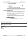
Connecting DC Power
Unless otherwise specified in the manual, the DC input to the equipment is floating in reference
to the ground. Any single pole can be externally grounded.
Due to the high current capability of DC power systems, care should be taken when connecting
the DC supply to avoid short-circuits and fire hazards.
Make sure that the DC power supply is electrically isolated from any AC source and that the
installation complies with the local codes.
The maximum permissible current capability of the branch distribution circuit that supplies power
to the product is 16A (20A for USA and Canada). The circuit breaker in the building installation
should have high breaking capacity and must operate at short-circuit current exceeding 35A (40A
for USA and Canada).
Before connecting the DC supply wires, ensure that power is removed from the DC circuit. Locate
the circuit breaker of the panel board that services the equipment and switch it to the OFF
position. When connecting the DC supply wires, first connect the ground wire to the
corresponding terminal, then the positive pole and last the negative pole. Switch the circuit
breaker back to the ON position.
A readily accessible disconnect device that is suitably rated and approved should be incorporated
in the building installation.
If the DC power supply is floating, the switch must disconnect both poles simultaneously.
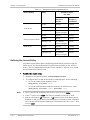
Connecting Data and Telecommunications Cables
Data and telecommunication interfaces are classified according to their safety status.
The following table lists the status of several standard interfaces. If the status of a given port
differs from the standard one, a notice will be given in the manual.
Ports
Safety Status
V.11, V.28, V.35, V.36, RS-530, X.21,
10 BaseT, 100 BaseT, Unbalanced E1,
E2, E3, STM, DS-2, DS-3, S-Interface
ISDN, Analog voice E&M
SELV
xDSL (without feeding voltage),
Balanced E1, T1, Sub E1/T1
TNV-1 Telecommunication Network Voltage-1:
Ports whose normal operating voltage is within the
limits of SELV, on which overvoltages from
telecommunications networks are possible.
FXS (Foreign Exchange Subscriber)
TNV-2 Telecommunication Network Voltage-2:
Ports whose normal operating voltage exceeds the
limits of SELV (usually up to 120 VDC or telephone
ringing voltages), on which overvoltages from
telecommunication networks are not possible. These
ports are not permitted to be directly connected to
external telephone and data lines.
FXO (Foreign Exchange Office), xDSL
(with feeding voltage), U-Interface
ISDN
TNV-3 Telecommunication Network Voltage-3:
Ports whose normal operating voltage exceeds the
limits of SELV (usually up to 120 VDC or telephone
ringing voltages), on which overvoltages from
telecommunication networks are possible.
Safety Extra Low Voltage:
Ports which do not present a safety hazard. Usually
up to 30 VAC or 60 VDC.
Always connect a given port to a port of the same safety status. If in doubt, seek the assistance
of a qualified safety engineer.
Always make sure that the equipment is grounded before connecting telecommunication cables.
Do not disconnect the ground connection before disconnecting all telecommunications cables.
Some SELV and non-SELV circuits use the same connectors. Use caution when connecting cables.
Extra caution should be exercised during thunderstorms.
When using shielded or coaxial cables, verify that there is a good ground connection at both
ends. The grounding and bonding of the ground connections should comply with the local codes.
The telecommunication wiring in the building may be damaged or present a fire hazard in case of
contact between exposed external wires and the AC power lines. In order to reduce the risk,
there are restrictions on the diameter of wires in the telecom cables, between the equipment
and the mating connectors.
Caution
To reduce the risk of fire, use only No. 26 AWG or larger telecommunication line
cords.
Attention
Pour réduire les risques s’incendie, utiliser seulement des conducteurs de
télécommunications 26 AWG ou de section supérieure.
Some ports are suitable for connection to intra-building or non-exposed wiring or cabling only. In
such cases, a notice will be given in the installation instructions.
Do not attempt to tamper with any carrier-provided equipment or connection hardware.
Electromagnetic Compatibility (EMC)
The equipment is designed and approved to comply with the electromagnetic regulations of
major regulatory bodies. The following instructions may enhance the performance of the
equipment and will provide better protection against excessive emission and better immunity
against disturbances.
A good ground connection is essential. When installing the equipment in a rack, make sure to
remove all traces of paint from the mounting points. Use suitable lock-washers and torque. If an
external grounding lug is provided, connect it to the ground bus using braided wire as short as
possible.
The equipment is designed to comply with EMC requirements when connecting it with unshielded
twisted pair (UTP) cables. However, the use of shielded wires is always recommended, especially
for high-rate data. In some cases, when unshielded wires are used, ferrite cores should be
installed on certain cables. In such cases, special instructions are provided in the manual.
Disconnect all wires which are not in permanent use, such as cables used for one-time
configuration.
The compliance of the equipment with the regulations for conducted emission on the data lines
is dependent on the cable quality. The emission is tested for UTP with 80 dB longitudinal
conversion loss (LCL).
Unless otherwise specified or described in the manual, TNV-1 and TNV-3 ports provide secondary
protection against surges on the data lines. Primary protectors should be provided in the building
installation.
The equipment is designed to provide adequate protection against electro-static discharge (ESD).
However, it is good working practice to use caution when connecting cables terminated with
plastic connectors (without a grounded metal hood, such as flat cables) to sensitive data lines.
Before connecting such cables, discharge yourself by touching ground or wear an ESD preventive
wrist strap.
FCC-15 User Information
This equipment has been tested and found to comply with the limits of the Class A digital device,
pursuant to Part 15 of the FCC rules. These limits are designed to provide reasonable protection
against harmful interference when the equipment is operated in a commercial environment. This
equipment generates, uses and can radiate radio frequency energy and, if not installed and used
in accordance with the Installation and Operation manual, may cause harmful interference to the
radio communications. Operation of this equipment in a residential area is likely to cause harmful
interference in which case the user will be required to correct the interference at his own
expense.
Canadian Emission Requirements
This Class A digital apparatus meets all the requirements of the Canadian Interference-Causing
Equipment Regulation.
Cet appareil numérique de la classe A respecte toutes les exigences du Règlement sur le matériel
brouilleur du Canada.
Warning per EN 55022 (CISPR-22)
Warning
Avertissement
Achtung
This is a class A product. In a domestic environment, this product may cause radio
interference, in which case the user will be required to take adequate measures.
Cet appareil est un appareil de Classe A. Dans un environnement résidentiel, cet
appareil peut provoquer des brouillages radioélectriques. Dans ces cas, il peut être
demandé à l’utilisateur de prendre les mesures appropriées.
Das vorliegende Gerät fällt unter die Funkstörgrenzwertklasse A. In Wohngebieten
können beim Betrieb dieses Gerätes Rundfunkströrungen auftreten, für deren
Behebung der Benutzer verantwortlich ist.
Français
Mise au rebut du produit
Afin de faciliter la réutilisation, le recyclage ainsi que d'autres formes de
récupération d'équipement mis au rebut dans le cadre de la protection de
l'environnement, il est demandé au propriétaire de ce produit RAD de ne pas
mettre ce dernier au rebut en tant que déchet municipal non trié, une fois
que le produit est arrivé en fin de cycle de vie. Le client devrait proposer des
solutions de réutilisation, de recyclage ou toute autre forme de mise au rebut
de cette unité dans un esprit de protection de l'environnement, lorsqu'il aura
fini de l'utiliser.
Instructions générales de sécurité
Les instructions suivantes servent de guide général d'installation et d'opération sécurisées des
produits de télécommunications. Des instructions supplémentaires sont éventuellement
indiquées dans le manuel.
Symboles de sécurité
Ce symbole peut apparaitre sur l'équipement ou dans le texte. Il indique des risques
potentiels de sécurité pour l'opérateur ou le personnel de service, quant à
l'opération du produit ou à sa maintenance.
Avertissement
Danger de choc électrique ! Evitez tout contact avec la surface marquée tant que le
produit est sous tension ou connecté à des lignes externes de télécommunications.
Mise à la terre de protection : la cosse ou la borne marquée devrait être connectée
à la prise de terre de protection du bâtiment.
•
Avant la mise en marche de l'équipement, assurez-vous que le câble de fibre
optique est intact et qu'il est connecté au transmetteur.
•
Ne tentez pas d'ajuster le courant de la commande laser.
•
N'utilisez pas des câbles ou connecteurs de fibre optique cassés ou sans
terminaison et n'observez pas directement un rayon laser.
•
L'usage de périphériques optiques avec l'équipement augmentera le risque pour
les yeux.
•
L'usage de contrôles, ajustages ou procédures autres que celles spécifiées ici
pourrait résulter en une dangereuse exposition aux radiations.
ATTENTION : Le rayon laser peut être invisible !
Les utilisateurs pourront, dans certains cas, insérer leurs propres émetteurs-récepteurs Laser SFP
dans le produit. Les utilisateurs sont avertis que RAD ne pourra pas être tenue responsable de
tout dommage pouvant résulter de l'utilisation d'émetteurs-récepteurs non conformes. Plus
particulièrement, les utilisateurs sont avertis de n'utiliser que des produits approuvés par
l'agence et conformes à la réglementation locale de sécurité laser pour les produits laser de
classe 1.
Respectez toujours les précautions standards de sécurité durant l'installation, l'opération et la
maintenance de ce produit. Seul le personnel de service qualifié et autorisé devrait effectuer
l'ajustage, la maintenance ou les réparations de ce produit. Aucune opération d'installation,
d'ajustage, de maintenance ou de réparation ne devrait être effectuée par l'opérateur ou
l'utilisateur.
Manipuler des produits sous tension
Règles générales de sécurité
Ne pas toucher ou altérer l'alimentation en courant lorsque le câble d'alimentation est branché.
Des tensions de lignes peuvent être présentes dans certains produits, même lorsque le
commutateur (s'il est installé) est en position OFF ou si le fusible est rompu. Pour les produits
alimentés par CC, les niveaux de tension ne sont généralement pas dangereux mais des risques
de courant peuvent toujours exister.
Avant de travailler sur un équipement connecté aux lignes de tension ou de télécommunications,
retirez vos bijoux ou tout autre objet métallique pouvant venir en contact avec les pièces sous
tension.
Sauf s'il en est autrement indiqué, tous les produits sont destinés à être mis à la terre durant
l'usage normal. La mise à la terre est fournie par la connexion de la fiche principale à une prise
murale équipée d'une borne protectrice de mise à la terre. Si une cosse de mise à la terre est
fournie avec le produit, elle devrait être connectée à tout moment à une mise à la terre de
protection par un conducteur de diamètre 18 AWG ou plus. L'équipement monté en châssis ne
devrait être monté que sur des châssis et dans des armoires mises à la terre.
Branchez toujours la mise à la terre en premier et débranchez-la en dernier. Ne branchez pas des
câbles de télécommunications à un équipement qui n'est pas mis à la terre. Assurez-vous que
tous les autres câbles sont débranchés avant de déconnecter la mise à la terre.
Français
Certains produits peuvent être équipés d'une diode laser. Dans de tels cas, une
étiquette indiquant la classe laser ainsi que d'autres avertissements, le cas échéant,
sera jointe près du transmetteur optique. Le symbole d'avertissement laser peut
aussi être joint.
Avertissement
Veuillez observer les précautions suivantes :
Français
Connexion au courant du secteur
Assurez-vous que l'installation électrique est conforme à la réglementation locale.
Branchez toujours la fiche de secteur à une prise murale équipée d'une borne protectrice de mise
à la terre.
La capacité maximale permissible en courant du circuit de distribution de la connexion alimentant
le produit est de 16A (20A aux Etats-Unis et Canada). Le coupe-circuit dans l'installation du
bâtiment devrait avoir une capacité élevée de rupture et devrait fonctionner sur courant de
court-circuit dépassant 35A (40A aux Etats-Unis et Canada).
Branchez toujours le câble d'alimentation en premier à l'équipement puis à la prise murale. Si un
commutateur est fourni avec l'équipement, fixez-le en position OFF. Si le câble d'alimentation ne
peut pas être facilement débranché en cas d'urgence, assurez-vous qu'un coupe-circuit ou un
disjoncteur d'urgence facilement accessible est installé dans l'installation du bâtiment.
Le disjoncteur devrait déconnecter simultanément les deux pôles si le système de distribution de
courant est de type IT.
Connexion d'alimentation CC
Sauf s'il en est autrement spécifié dans le manuel, l'entrée CC de l'équipement est flottante par
rapport à la mise à la terre. Tout pôle doit être mis à la terre en externe.
A cause de la capacité de courant des systèmes à alimentation CC, des précautions devraient
être prises lors de la connexion de l'alimentation CC pour éviter des courts-circuits et des risques
d'incendie.
Assurez-vous que l'alimentation CC est isolée de toute source de courant CA (secteur) et que
l'installation est conforme à la réglementation locale.
La capacité maximale permissible en courant du circuit de distribution de la connexion alimentant
le produit est de 16A (20A aux Etats-Unis et Canada). Le coupe-circuit dans l'installation du
bâtiment devrait avoir une capacité élevée de rupture et devrait fonctionner sur courant de
court-circuit dépassant 35A (40A aux Etats-Unis et Canada).
Avant la connexion des câbles d'alimentation en courant CC, assurez-vous que le circuit CC n'est
pas sous tension. Localisez le coupe-circuit dans le tableau desservant l'équipement et fixez-le
en position OFF. Lors de la connexion de câbles d'alimentation CC, connectez d'abord le
conducteur de mise à la terre à la borne correspondante, puis le pôle positif et en dernier, le
pôle négatif. Remettez le coupe-circuit en position ON.
Un disjoncteur facilement accessible, adapté et approuvé devrait être intégré à l'installation du
bâtiment.
Le disjoncteur devrait déconnecter simultanément les deux pôles si l'alimentation en courant CC
est flottante.
Contents
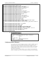
Chapter 1. Introduction 1.1 Overview.................................................................................................................... 1-1 Device Options ....................................................................................................... 1-2 Applications ............................................................................................................ 1-2 Features ................................................................................................................. 1-4 Service Types ..................................................................................................... 1-4 Service Level Agreement (SLA) Monitoring .......................................................... 1-4 Flow Classification .............................................................................................. 1-4 Tagging and Marking .......................................................................................... 1-5 Quality of Service (QoS) ..................................................................................... 1-6 Traffic Prioritization............................................................................................ 1-6 Queue Mapping and Marking .............................................................................. 1-7 Hierarchical Scheduling and Shaping Per Flow ..................................................... 1-7 Handling the Traffic Flow.................................................................................... 1-7 Ethernet OAM .................................................................................................... 1-8 Jumbo Frames and Egress MTU ........................................................................... 1-8 Link Redundancy ................................................................................................ 1-8 L2CP Handling .................................................................................................... 1-8 Fault Propagation ............................................................................................... 1-9 Management ...................................................................................................... 1-9 DHCP Client ...................................................................................................... 1-10 SFTP ................................................................................................................ 1-10 Statistics Collection .......................................................................................... 1-10 Synchronous Ethernet Timing ........................................................................... 1-10 Network Time Protocol ..................................................................................... 1-10 Diagnostic Tools ............................................................................................... 1-10 1.2 What’s New in This Version ...................................................................................... 1-12 1.3 Physical Description ................................................................................................. 1-13 1.4 Technical Specifications............................................................................................ 1-14 Chapter 2. Installation and Setup 2.1 2.2 2.3 2.4 2.5 2.6 Site Requirements and Prerequisites .......................................................................... 2-1 Package Contents ...................................................................................................... 2-2 Mounting the Unit ...................................................................................................... 2-2 Installing SFP Modules ................................................................................................ 2-2 Connecting to Ethernet Equipment ............................................................................. 2-3 Connecting to External Clock Source ........................................................................... 2-4 Connecting to a Balanced Clock Source ............................................................... 2-5 Connecting to an Unbalanced Clock Source ......................................................... 2-5 2.7 Connecting to ASCII Terminal ...................................................................................... 2-5 2.8 Connecting to Management Port ................................................................................ 2-6 2.9 Connecting to Power .................................................................................................. 2-7 Connecting to AC Power.......................................................................................... 2-7 Connecting to DC Power ......................................................................................... 2-7 Chapter 3. Operation 3.1 Turning On the Unit ................................................................................................... 3-1 3.2 Indicators .................................................................................................................. 3-2 ETX-204A Ver. 2.2
i
Table of Contents
Installation and Operation Manual
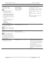
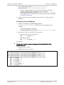
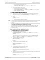
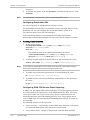
3.3 Configuration and Management Alternatives .............................................................. 3-2 Working with Terminal ............................................................................................ 3-3 Logging In .......................................................................................................... 3-7 Using the CLI ...................................................................................................... 3-8 Command Tree ................................................................................................. 3-10 Working with RADview .......................................................................................... 3-22 3.4 Startup .................................................................................................................... 3-23 Configuration Files ................................................................................................ 3-23 Loading Sequence ................................................................................................. 3-23 3.5 Using a Custom Configuration File ............................................................................ 3-24 3.6 Turning Off the Unit ................................................................................................. 3-25 Chapter 4. Configuration 4.1 Management Connectivity .......................................................................................... 4-2 Configuring the Host IP Settings.............................................................................. 4-2 Working with DHCP ............................................................................................ 4-2 Setting Host IP Parameters ................................................................................. 4-3 Configuring Device Information ............................................................................... 4-4 Configuring for SNMP Management ......................................................................... 4-5 SNMP Default Configuration ............................................................................... 4-5 Enabling or Disabling SNMPv3 ............................................................................. 4-6 Setting SNMP Communities................................................................................. 4-6 SNMPv3 Default Configuration ............................................................................ 4-6 Configuring SNMPv3 Parameters ......................................................................... 4-7 Configuring Network Managers ............................................................................. 4-15 Configuring Management Subnets .................................................................... 4-16 Configuring Network Manager Stations ............................................................. 4-16 Masking Traps to Network Managers ................................................................ 4-16 Controlling Management Access ............................................................................ 4-17 Defining the Access Policy..................................................................................... 4-18 Working with RADIUS ............................................................................................ 4-19 Configuring Radius Server Parameters .............................................................. 4-19 Displaying RADIUS Statistics ............................................................................. 4-20 Configuring Control Port Parameters ..................................................................... 4-20 Configuring User Access ........................................................................................ 4-21 4.2 Ethernet Ports ......................................................................................................... 4-23 Configuring Ethernet Port Parameters ................................................................... 4-24 Setting Second Network Interface as Network or User Port ................................... 4-26 Configuring the Layer 2 Control Processing ........................................................... 4-26 Default Layer 2 Control Processing Profile ........................................................ 4-27 Adding Layer 2 Control Processing Profiles ....................................................... 4-27 Deleting Layer 2 Control Processing Profiles ..................................................... 4-27 Configuring Layer 2 Control Processing Profiles................................................. 4-28 Displaying Ethernet Port Status ............................................................................. 4-28 Testing Ethernet Ports .......................................................................................... 4-29 Displaying Ethernet Port Statistics......................................................................... 4-30 Setting Sampling Interval for Port Statistics ...................................................... 4-30 Displaying Port Statistics .................................................................................. 4-30 Displaying Layer-2 Control Processing Statistics ................................................ 4-32 Clearing Statistics ............................................................................................. 4-33 4.3 Network Interface Redundancy ................................................................................ 4-33 Link Aggregation .............................................................................................. 4-34 1:1 Bidirectional Redundancy ........................................................................... 4-34 ii
ETX-204A Ver. 2.2
Installation and Operation Manual
4.4 4.5 4.6 4.7 4.8 4.9 Table of Contents
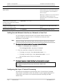
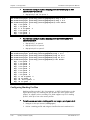
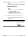
Configuring LAG .................................................................................................... 4-35 Configuring Link Protection ................................................................................... 4-39 Quality of Service (QoS) ........................................................................................... 4-41 Configuring Queue Mapping Profiles ...................................................................... 4-41 Default Configuration ....................................................................................... 4-41 Adding Queue Mapping Profiles ........................................................................ 4-42 Configuring Queue Mappings ............................................................................ 4-43 Configuring Marking Profiles .................................................................................. 4-44 Configuring Bandwidth Profiles ............................................................................. 4-46 Default Bandwidth Profiles ............................................................................... 4-46 Configuring Shaper Profiles .............................................................................. 4-47 Configuring Policer Profiles ............................................................................... 4-48 Configuring Policer Aggregates ......................................................................... 4-49 Configuring Queue Block Profiles ........................................................................... 4-50 Default Queue Block Profile .............................................................................. 4-51 Adding Queue Block Profiles ............................................................................. 4-51 Configuring Queue Block Profile Parameters ..................................................... 4-51 Configuring Queue Group Profiles ......................................................................... 4-52 Adding Queue Group Profiles ............................................................................ 4-52 Configuring Queue Group Profile Parameters .................................................... 4-52 Configuring WRED Profiles..................................................................................... 4-53 Flows ....................................................................................................................... 4-54 Defining Classifier Profiles ..................................................................................... 4-61 Configuring Flows ................................................................................................. 4-62 Configuring Management Flows ........................................................................ 4-65 Testing Flows........................................................................................................ 4-66 Displaying Flow Statistics ...................................................................................... 4-66 Ethernet OAM .......................................................................................................... 4-67 Configuring OAM CFM (Connectivity Fault Management) ........................................ 4-67 Configuring Maintenance Domains.................................................................... 4-67 Configuring Maintenance Associations .............................................................. 4-69 Configuring Maintenance Endpoints .................................................................. 4-70 Configuring Maintenance Endpoint Services ...................................................... 4-73 Configuring Destination NEs ............................................................................. 4-74 Configuring OAM CFM Service Event Reporting .................................................. 4-74 Displaying OAM CFM Statistics .......................................................................... 4-76 Configuring OAM EFM............................................................................................ 4-80 Clock Selection ......................................................................................................... 4-82 Configuring the Clock Domain ............................................................................... 4-82 Configuring the Clock Sources ............................................................................... 4-85 Configuring the Station Clock ................................................................................ 4-87 Fault Propagation..................................................................................................... 4-87 Default Configuration ........................................................................................... 4-88 Configuring Fault Propagation ............................................................................... 4-88 Adding Fault Propagation Entry ........................................................................ 4-88 Configuring Fault Propagation Parameters ........................................................ 4-89 Disabling Fault Propagation .............................................................................. 4-91 Date and Time ......................................................................................................... 4-91 Setting the Date and Time .................................................................................... 4-91 Displaying the Date and Time................................................................................ 4-92 Working with SNTP ............................................................................................... 4-92 Default Configuration ....................................................................................... 4-92 Configuring SNTP Parameters ........................................................................... 4-92 Defining SNTP Servers ...................................................................................... 4-93 ETX-204A Ver. 2.2
iii
Table of Contents
Installation and Operation Manual
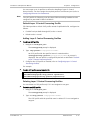
Configuring SNTP Server Parameters ................................................................. 4-93 4.10 Syslog ...................................................................................................................... 4-95 Configuring Syslog Parameters .............................................................................. 4-95 Displaying Syslog Statistics ................................................................................... 4-96 4.11 Configuring Temperature Threshold .......................................................................... 4-96 4.12 Clearing Device Statistics .......................................................................................... 4-97 4.13 Administration ......................................................................................................... 4-97 Working with the Inventory ................................................................................... 4-97 Standards and MIBs.......................................................................................... 4-97 Benefits ........................................................................................................... 4-98 Displaying Inventory Information ...................................................................... 4-98 Setting Administrative Inventory Information .................................................. 4-100 Example ......................................................................................................... 4-100 Displaying Environment ....................................................................................... 4-103 Displaying Software Versions .............................................................................. 4-104 Displaying CPU and Memory Utilization ................................................................ 4-104 File Operations ................................................................................................... 4-105 Downloading/Uploading Files .......................................................................... 4-106 Using CLI to Download/Upload Files ................................................................ 4-108 Copying Files Within Device ............................................................................ 4-109 Displaying Files Within Device ......................................................................... 4-109 Swapping Files ............................................................................................... 4-110 Deleting Files ................................................................................................. 4-110 Saving Configuration ........................................................................................... 4-111 Reset.................................................................................................................. 4-111 Resetting to Factory Defaults ......................................................................... 4-111 Resetting to User Defaults ............................................................................. 4-111 Restarting the Unit ......................................................................................... 4-112 Chapter 5. Monitoring and Diagnostics 5.1 Detecting Problems .................................................................................................... 5-1 LEDs ....................................................................................................................... 5-1 Alarms and Traps .................................................................................................... 5-1 5.2 Handling Events ......................................................................................................... 5-1 Working with the Event Log .................................................................................... 5-1 Working with Traps ................................................................................................. 5-4 Setting the Trap Delay ........................................................................................ 5-6 Masking Traps .................................................................................................... 5-6 Working with Trap Synchronization ..................................................................... 5-7 5.3 Running a Ping Test ................................................................................................... 5-9 5.4 Tracing the Route ...................................................................................................... 5-9 5.5 Technical Support .................................................................................................... 5-10 Chapter 6. Software Upgrade 6.1 6.2 6.3 6.4 Compatibility Requirements ........................................................................................ 6-1 Impact ....................................................................................................................... 6-2 Software Upgrade Options ......................................................................................... 6-2 Prerequisites .............................................................................................................. 6-2 Software Files ......................................................................................................... 6-2 System Requirements ............................................................................................. 6-2 6.5 Upgrading the Device Software via CLI ........................................................................ 6-3 Verifying the Host Parameters ................................................................................ 6-3 iv
ETX-204A Ver. 2.2
Installation and Operation Manual
Table of Contents
Pinging the PC ........................................................................................................ 6-3 Activating the SFTP Server....................................................................................... 6-4 Activating the TFTP Server ....................................................................................... 6-4 Downloading the New Software Release File ........................................................... 6-4 6.6 Upgrading the Device Software via the Boot Menu ..................................................... 6-5 Accessing the Boot Menu ........................................................................................ 6-5 Using the XMODEM Protocol ................................................................................... 6-6 Using TFTP .............................................................................................................. 6-7 6.7 Verifying Upgrade Results .......................................................................................... 6-8 Chapter 7. Configuring Typical Applications 7.1 Ethernet Private Line Application ................................................................................ 7-1 Configuring Management Connectivity..................................................................... 7-2 Configuring Classifier Profiles .................................................................................. 7-2 Configuring Flows ................................................................................................... 7-3 Appendix A. Connection Data Appendix B. Operation, Administration, and Maintenance (OAM) ETX-204A Ver. 2.2
v
Table of Contents
vi
Installation and Operation Manual
ETX-204A Ver. 2.2
Chapter 1
Introduction
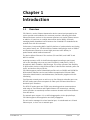
1.1
Overview
ETX-204A is a carrier Ethernet demarcation device owned and operated by the
service provider and installed at the customer premises, delivering SLA-based
Ethernet business services to the customer premises over native Ethernet access.
In addition, it functions as a mobile demarcation device (MDD), efficiently
managing mobile broadband traffic between the IP NodeB/ LTE eNodeB and the
network core with SLA assurance.
Furthermore, incorporating RAD’s SyncToP platform of synchronization and timing
over packet feature set, ETX-204A utilizes standard technologies such as 1588v2
and Synchronous Ethernet to ensure highly accurate traffic delivery in
packet-based mobile backhaul networks.
The device delivers Ethernet E-line services (EPL and EVPL) and is MEF 9 and
MEF 14 certified.
Incoming customer traffic is classified and mapped according to port-based
(all-in-one) bundling or by user port and CE VLAN-ID, VLAN priority, DSCP, IP
precedence, MAC, IP address, and Ethertype. This offers operators the flexibility
to differentiate services using different kinds of classification methods, police the
traffic, and enforce SLA per service.
ETX-204A supports powerful bandwidth profiles such as CIR/CBS and EIR/EBS for
differentiated Ethernet services and includes comprehensive Ethernet OAM
(Operation, Administration, and Maintenance) functionality together with SLA
monitoring.
Two Ethernet network ports as well as up to four Ethernet subscriber ports use
SFP/UTP combo ports that can operate as fiber optic SFP-based interfaces or
electrical RJ-45 interfaces.
The SFP/UTP combo ports are FE/GbE auto detecting and can accommodate a
wide range of Fast Ethernet and Gigabit Ethernet SFP transceivers, allowing
service providers to seamlessly connect customers located at different distances
from the device.
The network ports support 1:1 or LAG link aggregation. At the physical layer,
ETX-204A supports autonegotiation and fault propagation.
The unit can be managed via a local terminal port, via a dedicated out-of-band
Ethernet port, or via a user or network port.
ETX-204A Ver. 2.2
Overview
1-1
Chapter 1 Introduction
Installation and Operation Manual
Device Options
Several versions of the unit are available, offering different combinations of
Ethernet ports and enclosures.
•
Network ports – Up to two SFP/UTP combo ports that can act as SFP-based
fiber optic or 10/100/1000BaseT electrical. Port 2 can be configured as a
network or user port.
•
User ports – Up to four SFP/UTP combo ports that can act as SFP-based fiber
optic or 10/100/1000BaseT electrical, or up to five if port 2 is configured as a
user port.
The network/user SFP ports are FE/GbE auto detecting.
•
Note
Enclosure –Metal, 8.4” or 17.4”. For the allowed storage and operating
temperature range, refer to Technical Specifications.
The SFP/UTP combo ports operate in SFP-preferred mode. If an SFP is inserted
then the interface functions as an SFP-based fiber optic interface, otherwise it
functions as an electrical RJ-45 interface.
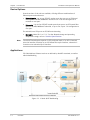
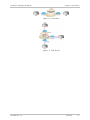
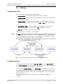
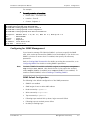
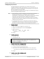
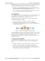
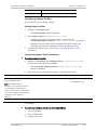
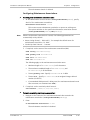
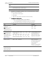
Applications
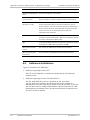
ETX-204A delivers Ethernet services as defined by the MEF standards, as well as
cellular backhauling.
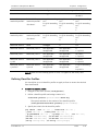
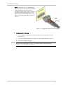
Figure 1-1. E-Node B/LTE Backhauling
1-2
Overview
ETX-204A Ver. 2.2
Installation and Operation Manual
Chapter 1 Introduction
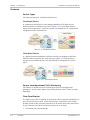
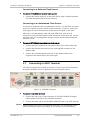
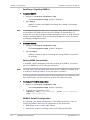
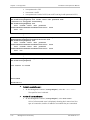
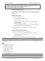
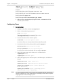
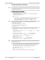
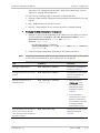
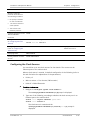
Figure 1-2. EPL Service
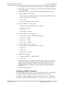
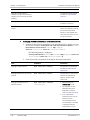
Figure 1-3. EVPL Service
ETX-204A Ver. 2.2
Overview
1-3
Chapter 1 Introduction
Installation and Operation Manual
Features
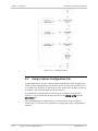
Service Types
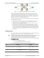
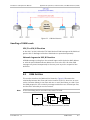
ETX-204A provides port- and flow-based services.
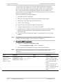
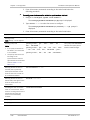
Port-Based Service
In a typical port-based (all-to-one bundling) application ETX-204A receives
different services via different user ports (Figure 1-4). This method achieves
clearer service separation, it does not require any marking for CoS, and provides
straightforward SLA measurement.
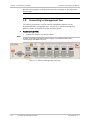
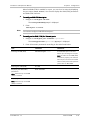
Figure 1-4. Port-Based Service
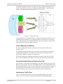
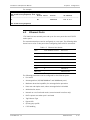
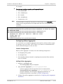
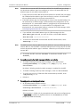
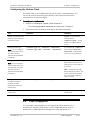
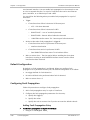
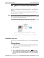
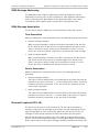
Flow-Based Service
In a typical flow-based application different services are assigned to different
Ethernet flows received by the same user port (Figure 1-5). This provides a
cheaper, more scalable solution, with a possibility of mixing different service
types.
Figure 1-5. Flow-Based Service
Service Level Agreement (SLA) Monitoring
ETX-204A is an effective tool for measuring the Service Level Agreement
parameters, such as Frame Delay, Frame Delay Variance (jitter), Frame Loss and
Availability.
Flow Classification
The ingress user traffic is mapped to the Ethernet flows using the following list of
per-port classification criteria. In the classifications, VLAN refers to the service
provider (outer) VLAN, previously referred to as SP-VLAN, while inner VLAN refers
to the Customer Entity VLAN, previously referred to as CE-VLAN.
•
1-4
Overview
Port-based (All to one bundling)
ETX-204A Ver. 2.2
Installation and Operation Manual
•
VLAN
•
VLAN + VLAN priority
•
VLAN + IP precedence
•
VLAN + DSCP
•
VLAN + source/destination MAC
•
VLAN + source/destination IP address
•
VLAN + inner VLAN
•
VLAN + VLAN priority + inner VLAN
•
VLAN + non-IP
•
VLAN + Ethertype
•
VLAN priority
•
IP precedence
•
DSCP
•
Source/destination MAC
•
Source/destination IP address
•
Non-IP
•
Ether Type
•
Untagged.
Chapter 1 Introduction
ETX-204A supports up to 270 Ethernet flows. Flows are unidirectional.
Tagging and Marking
ETX-204A supports several options for marking and tagging.
You can perform the following marking actions:
•
Overwrite inner or outer VLAN with a new value
•
Overwrite inner or outer VLAN p-bit with a new value.
You can perform the following tagging actions:
•
Add (push) outer VLAN, with p-bit value that can be copied from the original
value or set to a new value. When you add a new VLAN, the original outer
VLAN becomes the inner VLAN.
•
Remove (pop) outer VLAN and p-bit. When you remove a VLAN, the inner
VLAN becomes the outer VLAN.
•
Add (push) inner VLAN, with p-bit value that can be copied from the original
value or set to a new value
•
Remove (pop) inner VLAN and p-bit.
Only certain combinations of actions on the outer and inner VLAN are allowed.
Refer to Chapter 4 for details on the permitted combinations of actions.
ETX-204A Ver. 2.2
Overview
1-5
Chapter 1 Introduction
Installation and Operation Manual
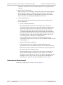
Quality of Service (QoS)
Different service types require different levels of QoS to be provided end-to-end.
QoS can be defined per subscriber as well as per flow. QoS has three aspects:
rate limitation, traffic shaping, and traffic prioritization.
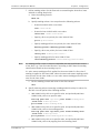
A single policer can be applied per flow, or a policer aggregate can be applied to a
group of up to five flows. The policers operate according to the dual token
bucket mechanism (CIR+CBS, EIR+EBS). A special mechanism compensates for
Layer 1 headers. Traffic can be limited to the line rate or the data rate.
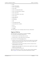
In addition, ETX-204A features unique p-bit re-marking capabilities that assign
color-specific p-bit values to Ethernet frames at network ingress to ensure
metering continuity across the Metro Ethernet network. User traffic that was
marked “Yellow” according to the CIR/EIR parameters by the device QoS engine is
assigned a new p-bit value to signal its status and priority, so that it is dropped
first by 802.1Q and 802.1ad network elements in the event of congestion. This is
especially useful in color-blind as well as color-aware networks with no “discard
eligible” (“yellow”) marking.
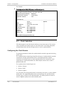
Figure 1-6. Policing and Hierarchical Scheduling/Shaping
Traffic Prioritization
Once traffic is classified to a flow, it can be mapped to Strict (Strict Priority)
queues or WFQ (Weighted Fair Queues):
1-6
•
Strict. The data flow set to the highest priority is transmitted first. If this data
flow stops, all tasks at lower priorities move up by one priority level. For
example, the data flow set to the second-highest priority is then transmitted
at the highest priority.
•
WFQ. Allows different scheduling priorities to statistically multiplex data flows
with different shares on the service. Each data flow has a separate FIFO
queue. A link transmitting at a data rate R, all non-empty data flows N are
served simultaneously according to the assigned share w, each at an average
rate of R/(w1 + w2 + w3 + … +wN). If one data flow stops, the remaining data
flows each receive a larger share w.
Overview
ETX-204A Ver. 2.2
Installation and Operation Manual
Chapter 1 Introduction
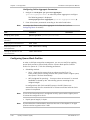
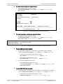
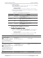
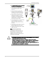
The WRED mechanism ensures that queues are not congested and high-priority
traffic is maintained. Each queue is assigned a WRED profile for which you can
configure the thresholds and probability to suit your needs.
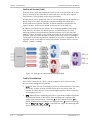
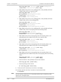
Figure 1-7. Queue Structure
Level 0 contains up to 30 queue blocks. Each block has eight queues and its own
scheduling (Strict and WFQ). For each queue block in level 0, there is a queue in
level 1 that represents the scheduling between the queue blocks in level 0. Flows
can be bound to each queue block in level 0.
Queue Mapping and Marking
The queue mapping functionality associates the user priorities with queue
numbers (CoS).
The marking functionality maps the user priority to the SP priority, according to
p-bit/DSCP/IP precedence. The marking can also be done according to color
(green and/or yellow) in addition to user priority.
The queue mapping and marking functionality is bound to each flow. For every
port, a queue mapping can be done for one type of user priority classification.
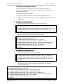
Hierarchical Scheduling and Shaping Per Flow
Every flow has its own queues and scheduler. ETX-204A supports up to 30 queue
blocks per queue group. There are 30 available queues for the network ports and
eight available queues for the user ports. Flows that are in the direction user port
to network port can be bound to one of 30 queues, and flows that are in the
direction network port to user port can be bound to one of eight queues.
Handling the Traffic Flow
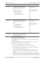
Table 1-1 provides an overview of the traffic handling stages. Refer also to
Figure 1-6 for an overview of policing and hierarchical scheduling/shaping.
ETX-204A Ver. 2.2
Overview
1-7
Chapter 1 Introduction
Installation and Operation Manual
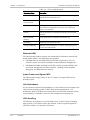
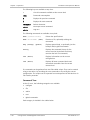
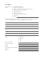
Table 1-1. Traffic Handling Stages
Processing Stage
Description
Classification
Classifying traffic such as email traffic, content streaming,
large document transmission, etc.
Policer per Flow or
Group of Flows
Policing the traffic within the flow or group of flows
CoS/Services
Dividing the services using a 3-bit field, specifying a priority
value between 0 (signifying best-effort) and 7 (signifying
priority real-time data)
Queues
‘Storing’ data that is transmitted according to the CoS level
specified
Rate Limitation/
Shaping
Ensuring that traffic is shaped to the desired rate
Scheduling
Scheduling and ‘regulating’ traffic
Editing and Marking
Adding or removing VLAN IDs, as well as marking the priority
on the outer VLAN header
Ethernet OAM
ETX-204A provides OAM to monitor and troubleshoot an Ethernet network and
quickly detect failures. Two OAM types are provided:
•
CFM OAM (End-to-end OAM) based on IEEE 802.1ag-D8 and Y.1731 for
continuity check, non-intrusive loopback, and performance management.
•
EFM OAM (Link OAM) according to IEEE 802.3-2005 (formerly IEEE 802.3ah)
for remote management and fault indication, including remote loopback,
dying gasp, and MIB parameter retrieval.
Jumbo Frames and Egress MTU
ETX-204A supports large frames of up to 12 Kbytes. The egress MTU can be
defined per port.
Link Redundancy
The unit features network link redundancy in a LAG architecture that supports the
LACP protocol according to 802.3-2005. Dual homing technology in a 1:1
architecture allows ETX-204A to be connected to two different upstream devices.
Link redundancy is available if two ports are configured as network ports.
L2CP Handling
ETX-204A can be configured to pass through Layer-2 control frames (including
other vendors’ L2CP frames) across the network, to peer-supported protocols
(IEEE 802.3-2005), or to discard L2CP frames.
1-8
Overview
ETX-204A Ver. 2.2
Installation and Operation Manual
Chapter 1 Introduction
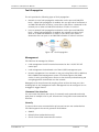
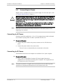
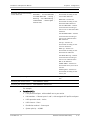
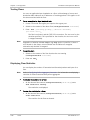
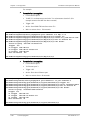
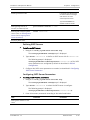
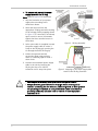
Fault Propagation
The unit provides the following types of fault propagation:
•
Network-to-user fault propagation mechanism on the port and OAM CFM
levels – When fault propagation is enabled, the user port shuts itself down or
an OAM CFM indication of failure is sent when a link failure is detected at the
network port or when an OAM CFM indication of failure is received.
•
User-to-network fault propagation mechanism on the port and OAM CFM
levels – When fault propagation is enabled, the network port shuts itself
down or an OAM CFM indication of failure is sent when a link failure is
detected at the user port or an OAM CFM indication of failure is received.
Figure 1-8. Fault Propagation
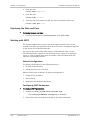
Management
ETX-204A can be managed as follows:
•
Local management via ASCII terminal connected to the V.24/RS-232 DCE
control port.
•
Local management via dedicated out of band (OOB) management port.
•
Remote management via a network or user port using Telnet SSH or RADview,
RAD’s SNMP-based management system. ETX-204A supports the SNMP
version 3 entity, providing secure access to the device by authenticating and
encrypting packets transmitted over the network.
Management can be performed by creating a flow to/from the host port, thus
enabling QoS on the management traffic. Management can be configured to use
untagged or tagged frames.
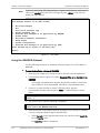
Command Line Interface
You can create data bases and scripts of commonly used commands and easily
apply them to multiple units in your infrastructure using RAD’s new command line
interface.
Security
To ensure client-server communication privacy and correct user authentication,
ETX-204A supports the security protocols listed below:
ETX-204A Ver. 2.2
•
SNMPv3
•
RADIUS (client authentication only)
•
SSH for Secure Shell communication session.
Overview
1-9
Chapter 1 Introduction
Installation and Operation Manual
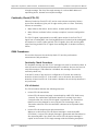
Syslog
The syslog protocol is a client/server-type protocol, featuring a standard for
forwarding log messages in an IP network and supports up to four syslog servers
at present. A syslog sender sends a small text message of less than 1024 bytes
to the syslog receiver. Syslog messages are sent via UDP in cleartext.
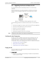
DHCP Client
When enabled, the DHCP client of ETX-204A requests an IP address, IP mask, and
default gateway from the DHCP server.
SFTP
SFTP (Secure File Transfer Protocol) is supported, to provide secure encrypted file
transfer using SSH.
Statistics Collection
ETX-204A collects performance statistics for the physical layers of the
network/user ports, Ethernet flows, OAM CFM, and Radius.
In addition, ETX-204A provides Rmon Statistics based on RFC 2819. In this
scenario, ETX-204A can send reports when one of the defined counters rises
above or drops below specified thresholds within the sampling period of time.
These reports can be sent as SNMP traps to defined network management
stations and/or written to the event log.
Synchronous Ethernet Timing
The unit’s SyncToP™ suite includes clock recovery using IEEE 1588v2 Precision
Timing Protocol, Synchronous Ethernet (Sync-E), and a built-in input/output clock
interface. The device can use Sync-E to receive the clock from the network, or
can transparently forward via 1588v2 with accurate timestamps.
ETX-204A supports up to two clock sources, which can be the user/network
Ethernet ports or the station clock. The timing subsystem automatically selects
the best timing source to use for synchronization. The Ethernet ports can
transmit SSM messages and distribute (in downstream direction) the quality of
the currently selected clock.
Network Time Protocol
The Network Time Protocol (NTP) provides the means of synchronizing all
managed elements across the network to a reliable clock source provided by
multiple servers. ETX-204A supports the client side of the NTP v.3 (RFC 1305).
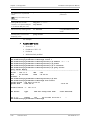
Diagnostic Tools
ETX-204A offers several types of diagnostic procedures:
•
1-10
Overview
Ping test –Check IP connectivity by pinging remote IP hosts.
ETX-204A Ver. 2.2
Installation and Operation Manual
ETX-204A Ver. 2.2
Chapter 1 Introduction
•
Trace route –Quickly trace a route from ETX-204A to any other network
device
•
Loopback tests:
Layer-1 loopback performed at the PHY of the physical ports. When the
loopback is active the data forwarded to a port is looped from the Tx
path to the Rx path, disrupting the traffic. This loopback cannot pass
through Ethernet bridges.
Layer-2/Layer-3 loopback on flows with optional MAC and/or IP address
swapping. When the loopback is active, ETX-204A can exchange the
source and destination MAC/IP addresses of the incoming packets. This
loopback passes through Ethernet bridges and routers, and does not
disrupt traffic flows that are not being tested.
Overview
1-11
Chapter 1 Introduction
Installation and Operation Manual
1.2
What’s New in This Version
The following features have been added for Version 2.2:
1-12
•
Full support for SyncE clock transfer per G.8262 including clock selection
mechanism
•
1588v2 end-to-end transparent clock support between all ETH ports
•
Color re-marking to change the VLAN priority according to the SLA
commitment (packet color)
•
Dying gasp for AC/DC power supply – Unit sends IEEE 802.3-2005 dying gasp
message and trap when power fails
•
RMON support per port (RFC 2819): etherStatsTable and alarm group are
supported
•
Inband management bridging allows management through user port,
Reducing need for separate management port
•
Bidirectional fault propagation based on CFM OAM messages
•
OAM-EFM (IEEE 802.3-2005) active mode – Power failure at a remote unit is
propagated to the management system via the nearest ETX-204A
•
Ethernet OAM loopback per IEEE 802.3-2005 on a single segment
(point-to-point)
•
Temperature monitoring:
The temperature of the unit can be displayed
Temperature threshold can be configured
Abnormal device temperature is reported.
•
Double VLAN mapping (CE-VLAN + SP-VLAN) allowed for management flows
and flows user -> network
•
Commands added: clear-statistics, show version
•
OAM CFM dynamic package (higher limits on number of allowed MDs and MAs,
dynamic MEP allocation, destination NEs)
•
Port being tested indicated by operational status displayed by show summary
•
SNTP multiple servers
•
Temperature-hardened version available in 8.4” in addition to 17.4” unit
•
Trap masking available for all traps
•
Trap synchronization
•
WRED profiles
•
Option for 24V DC power supply.
What’s New in This Version
ETX-204A Ver. 2.2
Installation and Operation Manual
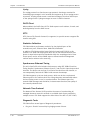
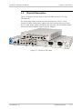
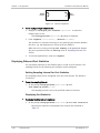
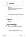
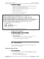
1.3
Chapter 1 Introduction
Physical Description
Figure 1-9 shows a 3D view of an 8.4-inch ETX-204A unit and a 17.4-inch
ETX-204A unit.
The front panels include network and user Ethernet ports. The 17.4-inch
enclosure includes a dual power supply at the front panel as well. On 8.4-inch
units, a single power supply is located on the rear panel. The ETX-204A interface
connections are described in greater detail in Chapter 2.
Figure 1-9. 3D View of ETX-204A
ETX-204A Ver. 2.2
Physical Description
1-13
Chapter 1 Introduction
Installation and Operation Manual
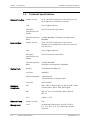
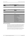
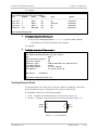
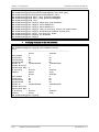
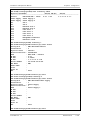
1.4
Network Interface
Technical Specifications
Number of Ports
Up to 2 SFP/UTP combo ports. The second port can
be configured as a network or user port.
Type
Fast or Gigabit Ethernet
Fiber Optic
Specifications and
Ranges
See SFP Transceivers data sheet
Electrical Operation
Mode
10/100/1000 Mbps, full duplex, autonegotiation,
MDI/MDIX
Number of Ports
Up to 4 SFP/UTP combo ports. If the second
network port is configured as a user port, there are
five user ports.
Type
Fast or Gigabit Ethernet
Fiber Optic
Specifications and
Ranges
See SFP Transceivers data sheet
Electrical Operation
Mode
10/100/1000 Mbps
Bit Rate
2.048 MHz/2.048 Mbps (E1)
Line Code
AMI/HDB3
Nominal Impedance
120Ω balanced
75Ω unbalanced (via adapter cable)
Connector
RJ-45 shielded
IEEE
802.3, 802.3u, 802.1d, 802.1q, 802.1p, 802.3-2005
(relevant parts), 802.3-2005, 802.1ag-D8
MEF
MEF 6 (E-Line – EPL and EVPL), MEF 9, MEF 10,
MEF 14
ITU-T
G.8262, Y.1731
Ethernet Flows
Number of Flows
270
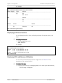
Management
Local
Via dedicated terminal port; V.24/RS-232 DCE;
9.6, 19.2, 38.4, 57.6, 115.2 kbps; DB-9 female
connector
User Interface
Station Clock
Standards
Compliance
1-14
Technical Specifications
Full duplex, autonegotiation, MDI/MDIX
ETX-204A Ver. 2.2
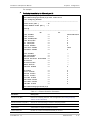
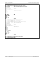
Installation and Operation Manual
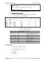
Indicators
Power
Physical
Physical
(ETX-204A/H)
Environment
Chapter 1 Introduction
Inband
Via one of the Ethernet ports
Out-of-band
Via dedicated management port
PWR (green)
Power status
TST/ALM (red)
Alarm and loopback status
NET 1, NET 2,
USER 3–6 (green)
Link/activity status of the network/user port
Station clock port
(green)
Clock port status
AC
100–240 VAC, 50/60 Hz, single power supply
DC
48V (-48 to 72 VDC), single power supply
24DC
24V (20 to 32VDC), single power supply
ACR
100–240 VAC, 50/60 Hz, dual power supply
DCR
48V (-48 to 72 VDC), dual power supply
24DCR
24V (20 to 32VDC), dual power supply
Power Consumption
15W
Height
43.7 mm (1.7 in)
Width
215 mm (8.4 in)
Depth
300 mm (11.8 in)
Weight
2.4 kg (5.2 lb)
Height
43.7 mm (1.7 in)
Width
440 mm (17.4 in)
Depth
240 mm (9.5 in)
Weight
3.1 kg (6.8 lb)
Temperature
ETX-204A: 0°C to 50°C (32°C to 122°F)
ETX-204A/H: -20 to 65°C (-4 to 149°F)
Humidity
ETX-204A Ver. 2.2
Up to 90%, non-condensing
Technical Specifications
1-15
Chapter 1 Introduction
1-16
Technical Specifications
Installation and Operation Manual
ETX-204A Ver. 2.2
Chapter 2
Installation and Setup
This chapter describes installation and setup procedures for the ETX-204A unit.
After installing the unit, refer to Chapter 3 for the operating instructions.
If a problem is encountered, refer to Chapter 5 for test and diagnostic
instructions.
Internal settings, adjustment, maintenance, and repairs may be performed only
by a skilled technician who is aware of the hazards involved.
Warning
Always observe standard safety precautions during installation, operation, and
maintenance of this product.
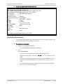
2.1
Site Requirements and Prerequisites
The ETX-204A device is intended for installation on desktop, 19” racks, and walls.
The following mounting kits are available from RAD:
•
RM-35 for mounting one or two regular ETX-204A units in a 19” rack
•
RM-34 for mounting one temperature-hardened ETX-204A unit in a 19” rack
•
WM-35 for mounting one regular ETX-204A unit on a wall
•
WM-34 for mounting one temperature-hardened ETX-204A unit on a wall.
AC-powered units should be installed within 1.5 m (5 ft) of an easily-accessible
grounded AC outlet capable of furnishing the voltage in accordance with the
nominal supply voltage.
DC-powered units require a -48 VDC power source, which must be adequately
isolated from the main supply.
Note
Refer also to the sections describing connections of AC and DC mains at the
beginning of the manual.
Allow at least 90 cm (36 in) of frontal clearance for operating and maintenance
accessibility. Allow at least 10 cm (4 in) clearance at the rear of the unit for signal
lines and interface cables.
The ambient operating temperature of ETX-204A is 0 to 50°C (32 to 122°F) and
the ambient temperature range of ETX-204A/H is -40 to 65°C (-40 to 149°F),
both at a relative humidity of up to 90%, non-condensing.
ETX-204A Ver. 2.2
Site Requirements and Prerequisites
2-1
Chapter 2 Installation and Setup
2.2
Installation and Operation Manual
Package Contents
The ETX-204A package includes the following items:
•
One ETX-204A unit
•
Matching SFP module(s) (if ordered)
•
AC power cord or DC connection kit
•
Optional accessories included if ordered:
CBL-DB9F-DB9M-STR, control port cable
RM-35 rack-mount kit for regular ETX-204A unit or RM-34 rack-mount kit
for temperature-hardened ETX-204A unit (if ordered)
WM-35 wall-mount kit for regular ETX-204A unit or WM-34 wall-mount kit
for temperature-hardened ETX-204A unit (if ordered).
2.3
Mounting the Unit
ETX-204A is designed for installation as a desktop unit. It can also be mounted in
a 19" rack or on a wall.
•
For rack mounting instructions, refer to the associated installation kit manual.
•
For wall mounting instructions, refer to the associated installation kit manual.
•
If ETX-204A is to be used as a desktop unit, place and secure the unit on a
stable, non-movable surface.
Refer to the clearance and temperature requirements in Site Requirements and
Prerequisites.
2.4
Installing SFP Modules
ETX-204A uses SFP modules with LC fiber optic connectors. The unit has SFP/UTP
combo ports that operate as fiber optic SFP-based interfaces when SFPs are
inserted.
Third-party SFP optical transceivers must be agency-approved, complying with the
local laser safety regulations for Class I laser equipment.
Warning
³
To install the SFP modules:
•
Note
2-2
Lock the wire latch of each SFP module by lifting it up until it clicks into place,
as illustrated in Figure 2-1.
Some SFP models have a plastic door instead of a wire latch.
Installing SFP Modules
ETX-204A Ver. 2.2
Installation and Operation Manual
Chapter 2 Installation and Setup
Figure 2-1. Locking the SFP Wire Latch
1. Carefully remove the dust covers from the SFP slot.
2. Insert the rear end of SFP into the socket, and push slowly backwards to
mate the connectors until the SFP clicks into place. If you feel resistance
before the connectors are fully mated, retract the SFP using the wire latch as
a pulling handle, and then repeat the procedure.
3. Remove the protective rubber caps from the SFP modules.
³
To remove the SFP module:
1. Disconnect the fiber optic cables from the SFP module.
2. Unlock the wire latch by lowering it downwards (as opposed to locking).
3. Hold the wire latch and pull the SFP module out of the Ethernet port.
Caution Do not remove the SFP while the fiber optic cables are still connected, as this
may result in mechanical and/or functional damage. For example the SFP module
clip on the module and in the socket may be chipped (mechanical issue) or the
redundancy network port switching process may not be properly completed
(functional issue).
2.5
Connecting to Ethernet Equipment
ETX-204A is connected to the Ethernet equipment via the SFP portion of the
combo port designated GbE or the UTP portion designated 10/100/1000BT
according to the relevant hardware configuration. Refer to Appendix A for the
RJ-45 connector pinout. The instructions below are illustrated using a sample
configuration with a regular (8.4”) ETX-204A enclosure.
³
To connect to the Ethernet equipment with fiber optic interface:
•
ETX-204A Ver. 2.2
Connect ETX-204A to the Ethernet equipment using a standard fiber optic
cable terminated with an LC connector.
Connecting to Ethernet Equipment
2-3
Chapter 2 Installation and Setup
Installation and Operation Manual
Figure 2-2. GbE Fiber Optic Connectors
³
To connect to the Ethernet equipment with a copper interface:
•
Note
Connect ETX-204A to the Ethernet network equipment using a standard
straight UTP cable terminated with an RJ-45 connector.
In order to comply with electromagnetic compatibility requirements, it is
recommended to use shielded cables when connecting to the RJ-45 port of the
ETX-204A electrical network or user interface.
Figure 2-3. 10/10/1000BT Electrical Connectors
2.6
Connecting to External Clock Source
ETX-204A is connected to an external clock source via a dedicated station clock
port, an RJ-45 connector designated EXT-CLK. The station clock port can be
connected to a balanced or unbalanced clock source. Refer to Appendix A for the
connector pinout.
Figure 2-4. EXT-CLK Connector
2-4
Connecting to External Clock Source
ETX-204A Ver. 2.2
Installation and Operation Manual
Chapter 2 Installation and Setup
Connecting to a Balanced Clock Source
³
To connect ETX-204A to a balanced clock source:
•
Connect the station clock port to the clock source using a shielded standard
UTP cable terminated with an RJ-45 connector.
Connecting to an Unbalanced Clock Source
To connect to equipment with an unbalanced interface, it is necessary to convert
the RJ-45 connector to a pair of BNC female connectors, in order to receive the
clock signal via one of the connectors and transmit the signal via the other.
RAD offers a suitable adapter cable, CBL-RJ45/2BNC/E1/X, with an RJ-45
connector at one end and two BNC female connectors at the other end. For this
particular cable, the receiving BNC connector is green and the transmitting BNC
connector is red.
³
To connect ETX-204A to an unbalanced clock source:
1. Connect the RJ-45 connector of the adapter cable to the station clock port.
2. Connect the external clock source to the receiving BNC connector of the
adapter cable.
3. Connect the transmitting BNC connector of the adapter cable to the
equipment that should receive the clock signal.
2.7
Connecting to ASCII Terminal
ETX-204A is connected to an ASCII terminal via a 9-pin D-type female connector
designated CONTROL. Refer to Appendix A for the connector pinout.
Figure 2-5. CONTROL Connector
³
To connect to an ASCII terminal:
1. Connect the male 9-pin D-type connector of CBL-DB9F-DB9M-STR straight
cable available from RAD to the CONTROL connector.
2. Connect the other end of the CBL-DB9F-DB9M-STR cable to an ASCII terminal.
Caution Terminal cables must have a frame ground connection. Use ungrounded cables
when connecting a supervisory terminal to a DC-powered unit with floating
ETX-204A Ver. 2.2
Connecting to ASCII Terminal
2-5
Chapter 2 Installation and Setup
Installation and Operation Manual
ground. Using improper terminal cable may result in damage to the supervisory
terminal port.
2.8
Connecting to Management Port
ETX-204A is connected to remote network management stations via the
dedicated Ethernet management port, an 8-pin RJ-45 connector designated
MNG-ETH. Refer to Appendix A for the connector pinout.
³
To connect to an NMS:
•
Note
Connect ETX-204A to an Ethernet switch.
In order to provide protection against surges, use shielded cables when
connecting to the MNG-ETH port.
Figure 2-6: Ethernet Management Connector
2-6
Connecting to Management Port
ETX-204A Ver. 2.2
Installation and Operation Manual
2.9
Chapter 2 Installation and Setup
Connecting to Power
Regular units are available with AC or DC power supply. For the exact specs, refer
to Technical Specifications in Chapter 1.
Warning
Before connecting or disconnecting any cable, the protective ground terminals of
this unit must be connected to the protective ground conductor of the mains (AC
or DC) power cord. If you are using an extension cord (power cable) make sure it
is grounded as well.
Any interruption of the protective (grounding) conductor (inside or outside the
instrument) or disconnecting of the protective ground terminal can make this
unit dangerous. Intentional interruption is prohibited.
Note
Refer also to the sections describing connections of AC and DC power at the
beginning of the manual.
Connecting to AC Power
AC power should be supplied via a 1.5 m (5 ft) standard power cable terminated
by a standard 3-prong socket. A cable is provided with the unit.
³
To connect AC power:
3. Connect the power cable to the power connector on the ETX-204A rear
panel.
4. Connect the power cable to the mains outlet.
The unit turns on automatically once connected to the mains.
Connecting to DC Power
Terminal block connectors with adapters are available for DC power supplies.
³
To connect DC power:
•
Note
ETX-204A Ver. 2.2
Refer to the Terminal Block Connector DC Power Supply Connection
supplement for instructions on wiring the DC adapters. This supplement can
be found at the end of this manual.
The power connectors of regular units are located at the rear while the power
connectors of temperature-hardened units are located at the front.
Connecting to Power
2-7
Chapter 2 Installation and Setup
2-8
Connecting to Power
Installation and Operation Manual
ETX-204A Ver. 2.2
Chapter 3
Operation
This chapter:
•
Explains power-on and power-off procedures
•
Provides a detailed description of the front panel controls and indicators and
their functions
•
Lists alternative methods of the product configuration, explaining the ASCII
terminal management application and CLI (Command Line Interface).
For a detailed explanation of parameters, see Chapter 4.
3.1
³
Turning On the Unit
To turn on ETX-204A:
•
Connect the power cord to the mains.
The PWR indicator lights up and remains lit as long as ETX-204A receives
power.
ETX-204A requires no operator attention once installed, with the exception of
occasional monitoring of front panel indicators. Intervention is only required
when ETX-204A must be configured to its operational requirements, or diagnostic
tests are performed.
ETX-204A Ver. 2.2
Turning On the Unit
3-1
Chapter 3 Operation
Installation and Operation Manual
3.2
Indicators
The unit's LEDs are located on the front panel (see Figure 3-1). Table 3-1 lists the
functions of the ETX-204A LED indicators.
Figure 3-1. Front Panel
Table 3-1. LEDs and Controls
Name
Type
Function
PWR
Green LED
ON – Power is ON
TST/ALM
Red LED
ON – One of the Ethernet links is down
Blinking – Diagnostic loopback is active
LINK/ACT
1, 2, 3, 4, 5, 6
Green LEDs
LINK/ACT
EXT-CLK
Green LEDs
LINK/ACT
MNG-ETH
Green LEDs
ON – Corresponding Ethernet link is OK
Blinking – Data is being transmitted or received on the corresponding
Ethernet link
ON – Station clock port is connected
ON – Management Ethernet link is OK
Blinking – Data is being transmitted or received on the management Ethernet
link
Note
The number of network ports and user ports and the corresponding number of
LEDs depend on the hardware configuration.
3.3
Configuration and Management Alternatives
Once installed, there are no special operating procedures for ETX-204A. The unit
operates automatically after it has started up. The unit’s operational status can
be constantly monitored.
ETX-204A can be managed via the following ports and applications:
3-2
•
Local management via an ASCII terminal connected to the RS-232 port.
Usually, preliminary configuration of the system parameters is performed via
ASCII terminal. Once the ETX-204A host IP parameters are set, you can access
it via Telnet SSH or SNMP for further configuration.
•
Remote inband management via user or network port or out-of-band via the
dedicated management port. Remote management is via Telnet or SNMP.
Configuration and Management Alternatives
ETX-204A Ver. 2.2
Installation and Operation Manual
Chapter 3 Operation
Alternatively, you can manage ETX-204A via a third-party SNMP-based NMS.
Refer to Chapter 5 for a trap list.
The following functions are supported by the ETX-204A management software:
•
Viewing system information
•
Modifying configuration and mode of operation, including setting system
default values and resetting the unit
•
Monitoring ETX-204A performance
•
Initiating connectivity tests
•
Uploading and downloading software and configuration files.
Working with Terminal
ETX-204A has a V.24/RS-232 asynchronous DCE port, designated CONTROL and
terminated in a 9-pin D-type female connector. The control port continuously
monitors the incoming data stream and immediately responds to any input string
received through this port.
³
To start a terminal control session:
1. Make sure all ETX-204A cables and connectors are properly connected.
2. Connect ETX-204A to a PC equipped with an ASCII terminal emulation
application (for example, HyperTerminal). Refer to Chapter 2 for details on
connecting to the control port.
3. Start the PC terminal emulation (in Windows XP: Select Start > All Programs >
Accessories > Communications> HyperTerminal to create a new terminal
connection).
The HyperTerminal application opens, and the Connection Description
dialog box is displayed.
ETX-204A Ver. 2.2
Configuration and Management Alternatives
3-3
Chapter 3 Operation
Installation and Operation Manual
Figure 3-2. HyperTerminal with Connection Description Dialog Box
4. Enter a name for the connection.
5. Select an icon to represent the terminal connection, or leave the default icon
selected.
6. Click <OK>.
The Connect To dialog box is displayed.
Figure 3-3. Connect To Dialog Box
3-4
Configuration and Management Alternatives
ETX-204A Ver. 2.2
Installation and Operation Manual
Chapter 3 Operation
7. Select a PC COM port to be used to communicate with ETX-204A, and click
<OK>.
The COM Properties dialog box is displayed.
Figure 3-4. COM1 Properties Dialog Box
8. Configure the communication port parameters as follows:
Bits per second: 9,600
Data bits: 8
Parity: None
Stop bits: 1
Flow control: None.
9. Click <OK> to close the COM Properties dialog box.
HyperTerminal is now ready for communication with the unit.
Note
It is not necessary to set the emulation type.
10. Power-up ETX-204A.
ETX-204A boots up. When the startup process is completed, you are
prompted to press <ENTER> to receive the login prompt.
ETX-204A Ver. 2.2
Configuration and Management Alternatives
3-5
Chapter 3 Operation
Installation and Operation Manual
Figure 3-5. HyperTerminal Window after Startup
11. Press <ENTER> until you receive the login prompt. Refer to Logging In for
details on logging in.
3-6
Configuration and Management Alternatives
ETX-204A Ver. 2.2
Installation and Operation Manual
Chapter 3 Operation
Figure 3-6. Login Prompt
Logging In
To prevent unauthorized modification of the operating parameters, ETX-204A
supports two access levels:
Note
³
•
Superuser can perform all the activities supported by the ETX-204A
management facility, including defining new users.
•
User access rights (full control or read only) are defined by the superuser.
Users are not allowed to create new users.
It is recommended to change default passwords to prevent unauthorized access
to the unit.
To enter as superuser:
1. At the User prompt (user>), Enter su and press <Enter>.
The Password prompt (password>) appears.
2. Enter 1234 as password and press <Enter>.
The base prompt ETX-204A# appears.
Superuser allows you to configure all parameters of ETX-204A and to change the
su and user passwords.
ETX-204A Ver. 2.2
Configuration and Management Alternatives
3-7
Chapter 3 Operation
³
Installation and Operation Manual
To enter as User:
1. Enter user as user name and press <Enter>.
2. Enter 1234 as password and press <Enter>.
The base prompt ETX-204A# appears.
Using the CLI
The CLI consists of commands organized in a tree structure, starting at the base
prompt ETX-204A#. The base prompt is the device name, which can be
configured in the system level (refer to Configuring Device Information in
Chapter 4). By default the device name is ETX-204A.
Commands that are not global are available only at their specific tree location. To
find out what commands are available at the current location, type ?. For a list of
the commands and their levels, refer to Command Tree.
To navigate down the tree, type the name of the next level. The prompt then
reflects the new location, followed by #. To navigate up, use the global command
exit. To navigate all the way up to the root, type exit all.
At the prompt, one or more level names separated by a space can be typed,
followed (or not) by a command. If only level names are typed, navigation is
performed and the prompt changes to reflect the current location in the tree. If
the level names are followed by a command, the command is executed, but no
navigation is performed and the prompt remains unchanged.
Note
To use show commands without navigating, type show followed by the level
name(s) followed by the rest of the show command.
In the following example, the levels and command were typed together and
therefore no navigation was performed, so the prompt has not changed.
ETX-204A#
ETX-204A# configure port ethernet 1 loopback local
ETX-204A# show configure port ethernet 1 loopback
Loopback : Local
Forever
ETX-204A#
Figure 3-7. Commands Without Level Navigation
3-8
Configuration and Management Alternatives
ETX-204A Ver. 2.2
Installation and Operation Manual
Chapter 3 Operation
In the following example, the levels were typed separately and the navigation is
reflected by the changing prompt.
ETX-204A#
ETX-204A# configure
ETX-204A>config# port
ETX-204A>config>port# ethernet 1
ETX-204A>config>port>eth(1)# loopback local
ETX-204A>config>port>eth(1)# show loopback
Loopback : Local
Forever
ETX-204A>config>port>eth(1)#
Figure 3-8. Commands With Level Navigation
Note
Level names are abbreviated in the prompt.
You can type only as many letters of the level or command as required by the
system to identify the level or command, for example you can enter
config manag to navigate to the management level.
In addition to being the default prompt, the # symbol also indicates a static entity
(such as a port) or already configured entity. The $ symbol indicates a new
dynamic entity (such as a flow) that takes several commands to configure. The
dynamic entity is created as inactive. After the configuration is completed, it is
activated by using the no shutdown command, as shown in the following
example.
ETX-204A#
ETX-204A# configure flows flow flow1
ETX-204A>config>flows>flow(flow1)$ ingress-port ethernet 3
ETX-204A>config>flows>flow(flow1)$ egress-port ethernet 1 queue 1 block 0/1
ETX-204A>config>flows>flow(flow1)$ classifier Classifier1
ETX-204A>config>flows>flow(flow1)$ no shutdown
ETX-204A>config>flows>flow(flow1)$exit
ETX-204A>config>flows#
Figure 3-9. Creating and Activating Flow
The shutdown command is also used to deactivate/disable a hardware element
(such as a port), while no shutdown enables/activates it.
CLI commands have the following basic format:
command [parameter]{ value1 | value2 | … | valuen }
[ optional parameter <value> ]
where:
ETX-204A Ver. 2.2
{}
Indicates that one of the values must be selected
[]
Indicates an optional parameter
<>
Indicates a value to be typed by user according to
parameter requirements
Configuration and Management Alternatives
3-9
Chapter 3 Operation
Installation and Operation Manual
The following keys are available at any time:
?
Lists all commands available at the current level
<Tab>
Command autocomplete
↑
Displays the previous command
↓
Displays the next command
<Backspace>
Deletes character
<Ctrl-C>
Interrupts current command
<Ctrl-Z>
Logs out
The following commands are available at any level:
echo [<text-to-echo>]
Echoes the specified text
exec <file-name> [echo]
Executes a file, optionally echoing the
commands
help [hotkeys] [globals]
Displays general help, or optionally just the
hotkeys and/or global commands
history
Displays the command history for the
current session (by default the history
contains the last 10 commands)
info [detail]
Displays information on the current
configuration
tree [detail]
Displays all lower command levels and
commands accessible from the current
context level
CLI commands can be gathered into text files called scripts. They can be created
using a text editor, by recording the user commands or by saving the current
configuration. The scripts can be imported from and exported to RAD devices via
file transfer protocols.
Command Tree
At the CLI root, the following categories are available:
•
configure
•
file
•
admin
•
root
•
global-commands.
Each category is detailed in the tables below.
3-10
Configuration and Management Alternatives
ETX-204A Ver. 2.2
Installation and Operation Manual
Chapter 3 Operation
Table 3-2. Commands in the configure category
Command
Description
configure
Enter configure level
|
chassis
Enter chassis level
|
|
show environment
Display hardware component statuses
|
|
temperature-threshold
Specify temperature thresholds
|
system
Configure system parameters
|
|
name
Configure name of device
|
|
contact
Configure contact person
|
|
location
Configure location of device
|
|
tftp
Configure TFTP parameters
|
|
clear-event-log
Clear event log
|
|
clear-cpu-utilization
Clear CPU utilization counters
|
|
show device-information
Display device information
|
|
show inventory-table
Display inventory information
|
|
show event-log
Display event log
|
|
show time
Display date and time
|
|
show cpu-utilization
Shows the CPU utilization
|
|
show buffers
Display memory buffer usage
|
|
inventory
Configure inventory entity
|
|
|
alias
Configure inventory entity alias
|
|
|
asset-id
Configure inventory entity asset ID
|
|
|
serial-number
Configure inventory entity serial number
|
|
|
show status
Display inventory entity status
|
|
date-and-time
Configure date & time parameters
|
|
|
date-format
Configure system date format
|
|
|
date
Configure system date
|
|
|
time
Configure system time
|
|
|
zone
Configure time zone and offset
|
|
|
sntp
Configure Simple Network Time Protocol parameters
|
|
|
|
poll-interval
Configure SNTP polling interval
|
|
|
|
server
Configure SNTP server
|
|
|
|
|
Configure SNTP server IP address
|
|
|
|
send-request
address
ETX-204A Ver. 2.2
Send SNTP request to server
Configuration and Management Alternatives
3-11
Chapter 3 Operation
Installation and Operation Manual
Command
Description
|
|
syslog
Configure syslog entities
|
|
|
address
Configure target address of syslog server
|
|
|
shutdown
Enable/disable logging of syslog entity
|
|
|
facility
Configure facility of device
|
|
|
severity-level
Configure severity level of device
|
|
|
port
Configure UDP port number
|
|
|
show statistics
Display syslog statistics
|
|
clock
Enter clock level
|
|
|
station
Enter station level (station is an E1/2MHz source for
synchronization)
|
|
|
|
shutdown
Enable or disable station clock
|
|
|
|
tx-clock-source
Set station timing to be derived from internal system
or E1/2MHz external source
|
|
|
|
interface-type
Set interface type
|
|
|
|
line-code
Set line code
|
|
|
|
rx-sensitivity
Set receiver sensitivity
|
|
|
domain
Enter domain level
|
|
|
|
sync-network-type
Set synchronization network type
|
|
|
|
quality
Set quality of clock
|
|
|
|
max-frequency-deviation
[Not supported in Ver. 2.2]
|
|
|
|
mode
Set clock mode
|
|
|
|
force
Force selection of a particular clock source
|
|
|
|
manual
Manually select a particular clock source
|
|
|
|
clear
Cancel previously issued force or manual command
|
|
|
|
clear-statistics
Clear statistics for clock sources
|
|
|
|
source
Enter clock source level
|
|
|
|
|
priority
Set priority
|
|
|
|
|
quality-level
Set quality level
|
|
|
|
|
wait-to-restore
Define amount of time that a previously failed
synchronization source must be fault free in order to
be considered available
|
|
|
|
|
hold-off
Define amount of time that signal failure must be
active before it is transmitted
|
|
|
|
|
clear-wait-to-restore
Cancel the wait-to-restore timer of a clock source
|
|
|
|
|
show status
Display status
3-12
Configuration and Management Alternatives
ETX-204A Ver. 2.2
Installation and Operation Manual
Command
Chapter 3 Operation
Description
|
|
|
|
|
show statistics
|
|
|
|
show status
|
management
Configure management parameters
|
|
user
Create/delete user
|
|
show users
Display users
|
|
host
Configure host parameters
|
|
|
dhcp
Enable or disable DHCP
|
|
|
ip-address
Configure host IP address
|
|
|
default-gateway
Configure IP address of default gateway
|
|
|
arp-timeout
Configure ARP timeout
|
|
|
show status
Display host status
|
|
snmp
Configure SNMP parameters
|
|
|
community
Configure SNMP read, write, and trap community
|
|
|
trap-mask
Mask specific alarm traps to all network managers
|
|
|
trap-delay
Configure delay for sending trap
|
|
|
snmp-engine-id-string
Text, administratively assigned. Maximum remaining
length 27
|
|
|
snmpv3
Enable or disable SNMPv3
|
|
|
show snmpv3 information
Display SNMPv3 information
|
|
|
user
Configure SNMPv3 user
|
|
|
|
shutdown
Activate or deactivate SNMPv3 user
|
|
|
|
authentication
Configure authentication for SNMPv3 user
|
|
|
|
privacy
Configure privacy for SNMPv3 user
|
|
|
access-group
Configure SNMPv3 access group
|
|
|
|
shutdown
Activate or deactivate SNMPv3 access group
|
|
|
|
context-match
Configure context match
|
|
|
|
read-view
Configure read view
|
|
|
|
write-view
Configure write view
|
|
|
|
notify-view
Configure notify view
|
|
|
security-to-group
Configure security for access group
|
|
|
|
shutdown
Activate or deactivate security for access group
|
|
|
|
group-name
Specify access group
|
|
|
view
Configure SNMPv3 view
|
|
|
|
Activate or deactivate
shutdown
ETX-204A Ver. 2.2
Display statistics
Display status
Configuration and Management Alternatives
3-13
Chapter 3 Operation
Command
Installation and Operation Manual
Description
|
|
|
|
mask
Configure SNMPv3 view mask
|
|
|
|
type
Configure SNMPv3 view type
|
|
|
community
Configure SNMPv3 community
|
|
|
|
shutdown
Activate or deactivate
|
|
|
|
name
Configure SNMPv3 community name
|
|
|
|
sec-name
Configure SNMPv3 community security name
|
|
|
|
tag
Configure SNMPv3 community tag
|
|
|
target-params
Configure SNMPv3 target parameters
|
|
|
|
shutdown
Activate or deactivate SNMPv3 target parameters
|
|
|
|
message-processing-model
Configure SNMPv3 target parameters message
processing model
|
|
|
|
version
Configure SNMPv3 target parameters version
|
|
|
|
security
Configure SNMPv3 target parameters security
|
|
|
target
Configure SNMPv3 target
|
|
|
|
shutdown
Activate or deactivate SNMPv3 target
|
|
|
|
target-params
Configure SNMPv3 target parameters
|
|
|
|
tag-list
Configure SNMPv3 target tag list
|
|
|
|
address
Configure SNMPv3 target address
|
|
|
|
trap-sync-group
Configure trap synchronization group with SNMPv3
managers
|
|
|
notify
Configure SNMPv3 notification
|
|
|
|
shutdown
Activate or deactivate SNMPv3 notification
|
|
|
|
tag
Configure SNMPv3 notification tag
|
|
|
|
bind
Configure SNMPv3 notification bind
|
|
|
notify-filter
Configure SNMPv3 notification filter
|
|
|
|
shutdown
Activate or deactivate SNMPv3 notification filter
|
|
|
|
type
Configure SNMPv3 notification filter type
|
|
|
|
mask
Configure SNMPv3 notification filter mask
|
|
|
notify-filter-profile
Configure SNMPv3 notification filter profile
|
|
|
|
shutdown
Activate or deactivate SNMPv3 notification filter
profile
|
|
|
|
profile-name
Configure SNMPv3 notification filter profile name
|
|
trap-sync-group
3-14
Configuration and Management Alternatives
Configure trap synchronization group with SNMPv3
managers
ETX-204A Ver. 2.2
Installation and Operation Manual
Chapter 3 Operation
Command
Description
|
|
|
target-params
Configure target parameters for trap synchronization
group with SNMPv3 managers
|
|
|
tag-list
Configure tag list for trap synchronization group
with SNMPv3 managers
|
|
show trap-sync
Display the trap synchronization information if
SNMPv3 is enabled
|
|
access
Configure management access
|
|
|
telnet
Configure telnet access
|
|
|
ssh
Configure SSH access
|
|
|
snmp
Configure SNMP access
|
|
|
auth-policy
Configure policy of authentication
|
|
radius
RADIUS parameters
|
|
|
server
Create/delete RADIUS server
|
|
|
|
address
Configure address of RADIUS server
|
|
|
|
shutdown
Enable/disable RADIUS server
|
|
|
|
key
Configure client and RADIUS server shared secret
|
|
|
|
retry
Configure number of request attempts from RADIUS
server
|
|
|
|
timeout
Configure timeout for a response from RADIUS
server
|
|
|
|
auth-port
Configure logical port to be used by the
authentication protocol
|
|
|
show status
Display RADIUS status
|
|
|
show statistics
Display RADIUS statistics
|
|
manager
Configure network manager
|
|
|
udp-port
Define UDP port used to send traps
|
|
|
trap-mask
Mask or unmask traps to network manager
|
|
|
trap-sync-group
Configure trap synchronization group with SNMPv1
managers
|
|
|
|
Configure trap masking for trap synchronization
group with SNMPv1 managers
|
|
show trap-sync
|
qos
Enter quality of service level
|
|
policer-profile
Configure a policer profile
|
|
|
Define the bandwidth for the policer profile
trap-mask
bandwidth
ETX-204A Ver. 2.2
Display the trap synchronization information if
SNMPv3 is not enabled
Configuration and Management Alternatives
3-15
Chapter 3 Operation
Installation and Operation Manual
Command
Description
|
|
|
traffic-type
Define the policed traffic type
|
|
|
compensation
Define how many bytes to compensate for layer 1
overhead
|
|
policer-aggregate
Configure policer aggregate that specifies a policer
profile to apply to a group of flows
|
|
|
policer
Define policer profile for the policer aggregate
|
|
|
show statistics
Display policer aggregate statistics
|
|
|
show flows
Display the flows corresponding to policer aggregate
|
|
|
clear-statistics
Clear policer aggregate statistics
|
|
|
rate-sampling-window
Configure interval for rate sampling statistics
|
|
shaper-profile
Configure shaper profile
|
|
|
bandwidth
Define the bandwidth for the shaper profile
|
|
|
compensation
Define how many bytes to compensate for layer 1
overhead
|
|
marking-profile
Configure a marking profile to map the P-bit, IP
precedence, or DHCP classifications to the egress
priority tags
|
|
|
Map the user priority to a priority marking value
|
|
queue-block-profile
Configure queue block profile
|
|
|
queue
Define queue
|
|
|
|
scheduling
Define the queue scheduling method
|
|
|
|
depth
Define the queue length
|
|
queue-group-profile
Configure queue group profile
|
|
|
queue-block
Configure queue block
|
|
|
|
name
Define the name of the queue block
|
|
|
|
profile
Define the queue block profile for the queue block
|
|
|
|
bind
Bind to next level block in specific queue
|
|
|
|
shaper
Define the shaper profile for the queue block
|
|
queue-map-profile
Define a queue map profile to map the P-bit, IP
precedence, or DSCP classifications to internal
priority queues (classes of service)
|
|
|
Define the mapping between the user priority and
the queue id
|
|
wred-profile
|
3-16
|
mark
map
color
Configuration and Management Alternatives
Configure WRED profile
Configure the minimum and maximum queue usage
threshold, and percentage of packets to drop when
queue reaches maximum usage threshold
ETX-204A Ver. 2.2
Installation and Operation Manual
Chapter 3 Operation
Command
Description
|
fault
Enter fault level
|
|
fault-propagation
Configure fault propagation
|
|
|
action-on-group
Action(s) to perform in order to propagate a fault
|
|
|
trigger
Trigger for propagating fault
|
|
|
wait-to-restore
Define the time between recovery and resumption
of transmission
|
|
cfm
Enter fault CFM level
|
|
|
service
Configure event reporting for service
|
|
|
|
Define event reporting type for service
|
oam
Enter OAM level
|
|
efm
Enter OAM EFM level
|
|
|
Configure OAM EFM descriptor
|
|
cfm
Enter OAM CFM level
|
|
|
multicast-addr
Define the multicast address for OAM messages
|
|
|
maintenance-domain
Configure a maintenance domain (MD)
|
|
|
|
name
Define the name of the MD
|
|
|
|
md-level
Define the level of the MD
|
|
|
|
proprietary-cc
Define whether the OAM protocol of the MD is
standard or pre-standard
|
|
|
|
maintenance-association
Configure a maintenance association (MA)
|
|
|
|
|
name
Define the name of the MA
|
|
|
|
|
ccm-interval
Define the continuity check interval of the MA
|
|
|
|
|
mep
Configure a maintenance endpoint (MEP)
|
|
|
|
|
|
remote-mep
Define a remote MEP for the MEP
|
|
|
|
|
|
show remote-mep status
Display status of remote MEP
(show remote-mep <remote-mep-id> status)
|
|
|
|
|
|
dest-addr-type
Define MAC address types sent in OAM continuity
check messages and in performance measurement
messages, as standard multicast address or
user-defined unicast address
|
|
|
|
|
|
dest-mac-addr
Define the unicast MAC address sent in OAM CCM
messages if you defined unicast MAC address type
for CCM messages
|
|
|
|
|
|
continuity-verification
Define continuity verification as CC-based or
lb-based (only if OAM protocol is pre-standard and
ccm-initiate is enabled)
|
|
|
|
|
|
ccm-initiate
Enable or disable continuity check messages
frames-report
descriptor
ETX-204A Ver. 2.2
Configuration and Management Alternatives
3-17
Chapter 3 Operation
Installation and Operation Manual
Command
Description
|
|
|
|
|
|
ccm-priority
Define the priority of the CC message
|
|
|
|
|
|
lbm
Configure OAM loopback
|
|
|
|
|
|
linktrace
Configure OAM link trace
|
|
|
|
|
|
classification
Associate the MEP with a classifier profile or VLAN
|
|
|
|
|
|
shutdown
Activate or deactivate the MEP
|
|
|
|
|
|
show status
Display status of MEP
|
|
|
|
|
|
show lbm-results
Display result of OAM loopback
|
|
|
|
|
|
show linktrace-results
Display result of OAM link trace
|
|
|
|
|
|
service
Configure MEP service
|
|
|
|
|
|
|
shutdown
Activate or deactivate the MEP service
|
|
|
|
|
|
|
delay-threshold
Define delay threshold for the MEP service
|
|
|
|
|
|
|
delay-var-threshold
Define delay variation threshold for the MEP service
|
|
|
|
|
|
classification
Associate service with p-bit
|
|
|
|
|
|
interval
Define interval for performance measurement
messages to service remote NEs
|
|
|
|
|
|
|
clear-statistics
Clear the OAM CFM statistics for service
|
|
|
|
|
|
|
show statistics
Display the OAM CFM statistics for service
|
|
|
|
|
|
|
dest-ne
Configure destination NE
|
|
|
|
|
|
|
|
remote
Define remote MAC address or remote MEP ID
|
|
|
|
|
|
|
|
pm
Enable or disable performance measuring
|
|
|
|
|
|
|
|
clear-statistics
Clear the OAM CFM statistics for destination NE
|
|
|
|
|
|
|
|
show statistics
Display the OAM CFM statistics for destination NE
|
port
Enter configure port level
|
|
rate-sampling-window
Configure interval for rate sampling statistics
|
|
show summary
Display the status of all Ethernet ports
|
|
l2cp-profile
Define L2CP profile
|
|
|
mac
Define MAC address L2CP action
|
|
|
default
Default action for undefined control protocols
|
|
|
protocol
Choose specific protocol
|
|
ethernet
Configure Ethernet port
|
|
|
name
Define port name
|
|
|
shutdown
This command administratively disables a port. The
no form of this command administratively enables a
port.
3-18
Configuration and Management Alternatives
ETX-204A Ver. 2.2
Installation and Operation Manual
Chapter 3 Operation
Command
Description
|
|
|
auto-negotiation
Configure auto negotiation ability
|
|
|
max-capability
Configure maximum capability advertising
|
|
|
speed-duplex
This command configures the speed and duplex of
an Ethernet port when auto negotiation is disabled.
|
|
|
tag-ethernet-type
This command specifies the Ethertype expected in
Ethernet packet
|
|
|
tx-ssm
Enable or disable transmitting of clock availability
and quality via SSM
|
|
|
efm
Enable or disable link OAM EFM for Ethernet port
|
|
|
|
Define SNMP tunneling for OAM EFM
|
|
|
egress-mtu
Define the maximum transmission unit (MTU)
|
|
|
queue-group
Define queue group profile for port
|
|
|
loopback
This command puts the specified port into a
loopback mode. The no form of the command
disables the specified type of lookback.
|
|
|
l2cp
Assign L2CP profile to Ethernet port
|
|
|
functional-mode
Determine if second network port works in user
mode or network. If in network then redundancy is
available
|
|
|
clear-statistics
Clear Ethernet port statistics
|
|
|
clear-l2cp-statistics
Clear L2CP statistics
|
|
|
dhcp-request
Configure whether DHCP request should be sent
whenever the port is activated
|
|
|
show status
Display Ethernet port status
|
|
|
show statistics
Display Ethernet port statistics
|
|
|
show oam-efm
Display OAM EFM status
|
|
|
show oam-efm-statistics
Display OAM EFM statistics
|
|
|
show loopback
Display loopback status
|
|
|
show l2cp-statistics
Display L2CP statistics
|
|
lag
|
|
|
shutdown
Activate or deactivate the LAG
|
|
|
admin-key
Define an admin key that indicates the port speed
|
|
|
bind
Bind a port to the LAG
|
|
|
lacp
Enable the LACP protocol on the LAG
|
|
|
distribution-method
Define the distribution method
snmp-tunneling
Configure LAG
ETX-204A Ver. 2.2
Configuration and Management Alternatives
3-19
Chapter 3 Operation
Installation and Operation Manual
Command
Description
|
|
|
sys-priority
Assign value used to build LAG ID, which determines
aggregation precedence
|
|
|
show members-status
Display the status of the LAG members
|
|
|
show members-statistics
Display statistics for the LAG members
|
flows
Enter flows level
|
|
rate-sampling-window
Configure interval for rate sampling statistics
|
|
show summary
Display information for all flows
|
|
classifier-profile
Configure a classifier profile
|
|
|
Specifies the criteria for the classifier profile
|
|
flow
Configure flow
|
|
|
shutdown
Activate or deactivate the flow
|
|
|
classifier
Associate the flow with a classifier profile
|
|
|
drop
Discard traffic transmitted via the flow
|
|
|
policer
Associate the flow with a policer profile or aggregate
|
|
|
mark
Enter marking level for overwriting VLAN or inner
VLAN
|
|
|
|
vlan
Overwrite VLAN with a new value
|
|
|
|
marking-profile
Overwrite p-bit for VLAN as specified by marking
profile
|
|
|
|
p-bit
Overwrite p-bit for VLAN
|
|
|
|
inner-vlan
Overwrite inner VLAN
|
|
|
|
inner-marking-profile
Overwrite p-bit for inner VLAN as specified by
marking profile
|
|
|
|
inner-p-bit
Overwrite p-bit for inner VLAN
|
|
|
vlan-tag
Perform push/pop of VLAN or inner VLAN, optionally
with p-bits
|
|
|
ingress-port
Define the ingress port of the flow
|
|
|
egress-port
Define the egress port of the flow
|
|
|
test
This command puts the specified flow into a
loopback mode. The no form of the command
disables the specified type of loopback.
|
|
|
show statistics
Display statistics for the flow
|
|
|
clear-statistics
Clear statistics for the flow
|
|
|
show test
Display flow test status
|
protection
Configure link protection
|
|
Define Ethernet group
3-20
match
ethernet-group
Configuration and Management Alternatives
ETX-204A Ver. 2.2
Installation and Operation Manual
Chapter 3 Operation
Command
Description
|
|
|
bind
Add/remove protection and working ports
|
|
|
shutdown
Activate or deactivate Ethernet group
|
|
|
oper-mode
Define protection mode as 1-to-1 or manual
|
|
|
revertive
Define whether port recovery mode is revertive
(traffic switched back to the primary port after it
recovers)
|
|
|
wait-to-restore
Define time between recovery and resumption of
transmission
|
|
|
tx-down-duration-upon-flip
Define period of time that failed link stops
transmitting to report the failure
|
|
|
force-active-port
Define if port is forced to be active
|
|
|
show status
Display protection status
|
terminal
Configure control port parameters
|
|
baud-rate
Define control port data rate
|
|
timeout
Define security timeout
|
|
length
Define number of rows to display
Table 3-3. Commands in the file category
Command
Description
file
Enter file level
|
copy
Copy files
|
swap
Swap files
|
delete
Delete file
|
dir
Displays files in base directory
|
show version
Display active, main, and backup software file
versions, dates, and times
Table 3-4. Commands in the admin category
Command
Description
admin
Administrative commands
|
reboot
Restart the device
|
factory-default
Reset the device to factory defaults
|
user-default
Reset the device to user defaults
ETX-204A Ver. 2.2
Configuration and Management Alternatives
3-21
Chapter 3 Operation
Installation and Operation Manual
Table 3-5. Commands in the root category
Command
Description
clear-statistics
Clear statistics for Ethernet ports, flows, and OAM
services
Table 3-6. Commands in the global-commands category
Command
Description
global-commands
Global commands can be typed at any level
|
exit
Return to previous level in the commands hierarchy
|
tree
Display the commands hierarchy from current
context
|
help
Display help
|
history
Display commands history
|
echo
Echo the text that is typed in
|
exec
Execute a file
|
logout
Log out this system
|
info
Print configuration info
|
ping
Verify the reachability of a remote host
|
save
Save user configuration
|
trace-route
Determine the route to a destination address
Working with RADview
RADview-EMS is a user-friendly and powerful SNMP-based element management
system (EMS), used for planning, provisioning and managing heterogeneous
networks. RADview-EMS provides a dedicated graphical user interface (GUI) for
monitoring RAD products via their SNMP agents. RADview-EMS for ETX-204A is
bundled in the RADview-EMS package for PC (Windows-based) or Unix.
For more details about this network management software, and for detailed
instructions on how to install, set up, and use RADview, contact your local RAD
partner or refer to the RADview-EMS User's Manual at the RAD website.
3-22
Configuration and Management Alternatives
ETX-204A Ver. 2.2
Installation and Operation Manual
3.4
Chapter 3 Operation
Startup
Configuration Files
The following files contain configuration settings:
•
factory-default – Contains the manufacturer default settings
•
running-config – Contains the current configuration that is different from the
default configuration
•
startup-config – Contains saved non-default user configuration. This file is
not automatically created. You can use the save or copy command to create
it.
•
user-default-config – Contains default user configuration. This file is not
automatically created. You can use the copy command to create it.
•
main-sw – Contains the active software image.
Refer to Chapter 4 for details on file operations.
The save command is used to save the user configuration. Some commands that
reset the device also erase the saved user configuration by copying another file
to it before the reset. Refer to Figure 3-10for details.
Note
Figure 3-10. Commands That Reset Device/Copy Configuration Files
Loading Sequence
At startup, the device boots from the startup-config file, or the user-default file,
or the factory-default file, in the sequence shown in Figure 3-11. If none of these
files exist, the device boots using hard-coded defaults.
If the loading of startup-config or the user-default file fails, the file is deleted,
the loading failure event is written in the event log, and the device reboots. After
the reboot the device again attempts to load configuration files in the sequence
shown in Figure 3-11.
To display the parameter values after startup, use the info [detail]
command.
ETX-204A Ver. 2.2
Startup
3-23
Chapter 3 Operation
Installation and Operation Manual
Figure 3-11. Loading Sequence
3.5
Using a Custom Configuration File
In large deployments, often a central network administrator sends configuration
scripts to the remote locations and all that remains for the local technician to do
is to replace the IP address in the script or other similar minor changes (using any
text editor), and then download the file to the device.
To download the configuration file, use the copy command, as explained in
Chapter 4. It is recommended to copy the file to both startup-config and the
user-default file.
After downloading the configuration file, the unit must be reset in order to
execute the file. After the unit completes its startup, the custom configuration is
complete.
3-24
Using a Custom Configuration File
ETX-204A Ver. 2.2
Installation and Operation Manual
3.6
³
Turning Off the Unit
To power off the unit:
•
ETX-204A Ver. 2.2
Chapter 3 Operation
Remove the power cord from the power source.
Turning Off the Unit
3-25
Chapter 3 Operation
3-26
Turning Off the Unit
Installation and Operation Manual
ETX-204A Ver. 2.2
Chapter 4
Configuration
This chapter lists the commands used to configure ETX-204A and explains their
parameters.
This chapter includes the following sections:
•
Management Connectivity
•
Ethernet Ports
•
Network Interface Redundancy
•
Quality of Service (QoS)
•
Flows
•
Ethernet OAM
•
Clock Selection
•
Fault Propagation
•
Date and Time
•
Syslog
•
Configuring Temperature Threshold
•
Clearing Device Statistics
•
Working with the Inventory
•
Displaying Environment
•
Displaying Software Versions
•
Displaying CPU and Memory Utilization
•
File Operations
•
Saving Configuration
•
Reset.
For a list of commands and their context, refer to Chapter 3.
Note
ETX-204A Ver. 2.2
When you enter a level that causes the creation of a dynamic entity, $ is
displayed at the end of the prompt until you exit the entity level. The next time
you enter the entity level, # is displayed at the end of the prompt. For the
purposes of illustration, # is usually shown at the end of the prompts in this
chapter. Examples of dynamic entities include QoS profiles and OAM CFM entities.
Management Connectivity
4-1
Chapter 4 Configuration
Installation and Operation Manual
4.1
Management Connectivity
Usually, initial configuration of the management parameters is performed via
ASCII terminal. Once the ETX-204A host IP parameters have been set and the
management flows to/from the host have been defined, it is possible to access it
via Telnet or RADview for operation configuration. Perform the following steps in
order to configure ETX-204A for management:
•
Configuring the Host IP Settings
•
Configuring Device Information
•
Configuring for SNMP Management
•
Controlling Management Access
•
Configuring User Access.
Configuring the Host IP Settings
ETX-204A can be managed by a network management station, located on the
LAN and connected to one of the unit’s Ethernet ports. In order to establish a
proper connection, it is necessary to configure the host IP address, the subnet
mask and a default gateway. In addition, for management you must define flows
between the host and network port with the following conditions (see
Configuring Management Flows for an example of defining management flows):
•
The flow to the host should use classification untagged, or tagged with the
management VLAN if applicable
•
The flow from the host should forward all traffic (classification “all”), with
push action of the management VLAN and priority if applicable
•
The flows to/from the host can also use classification VLAN + inner VLAN.
You can obtain the host IP parameters via DHCP if enabled, otherwise you can
configure the host IP parameters manually.
Working with DHCP
To facilitate integration of a new device into a DHCP IP network, if DHCP is enabled
then ETX-204A requests IP host parameters from the DHCP server upon booting
up. ETX-204A is shipped with the DHCP client enabled.
Note
To enable IP connectivity in DHCP mode, make sure that the relevant port has
been made accessible.
Disabling DHCP
³
To disable the DHCP client:
1. Navigate to configure management host 1.
The config>mngmnt>host(1)# prompt is displayed.
Note
4-2
When you navigate to the host context you provide a host index that is always 1.
Management Connectivity
ETX-204A Ver. 2.2
Installation and Operation Manual
Chapter 4 Configuration
2. Enter no dhcp.
ETX-204A resets the host IP address to 0.0.0.0, while preserving the IP
mask and default gateway values. Telnet/SSH connections to ETX-204A
are terminated. The unit is not accessible via Internet until you manually
configure an IP address and default gateway, unless you entered a
default IP address previously with the dhcp command.
Enabling DHCP
To enable DHCP, remove the defined host IP address and default gateway, then
enable DHCP
³
To enable the DHCP client and acquire IP parameters:
1. Navigate to configure management host 1.
The config>mngmnt>host(1)# prompt is displayed.
2. Enter the following commands:
no ip-address
no default-gateway.
The IP address and mask are set to 0.0.0.0, and the default gateway is
removed.
3. Enter dhcp [default-ip <IP-address/IP-mask>].
ETX-204A starts broadcasting requests for an IP address. When the DHCP
server is found, ETX-204A receives from it all necessary host IP
parameters. If specified, a default IP address is associated with ETX-204A
in the event the DHCP server is unavailable.
Note
When the IP address lease is about to expire, the DHCP client automatically
requests a lease extension.
Setting Host IP Parameters
You can enter the host IP address and default gateway manually when DHCP is
disabled. You can also specify the ARP timeout.
³
To define the IP parameters manually:
1. Navigate to configure management host 1.
The config>mngmnt>host(1)# prompt is displayed.
Note
When you navigate to the host context, you provide a host index that is always 1.
2. Enter all necessary commands according to the tasks listed below.
ETX-204A Ver. 2.2
Management Connectivity
4-3
Chapter 4 Configuration
Installation and Operation Manual
Task
Command
Comments
Defining the host IP address and
IP mask
ip-address <host-IP-address>/<IP-mask>
The IP mask is a decimal number that
specifies the number of high-order
consecutive bits set to 1 in the mask (refer
to example below).
For example, to define IP address
192.178.1.175 with IP mask 255.255.255.0,
enter:
ip-address 192.178.1.175/24
default-gateway <gateway-IP-address>
The default gateway must be in the same
subnet as the host
Specifying the ARP timeout
arp-timeout <seconds>
The value can be 300–1,000,000
Displaying the host IP settings
show status
Note: This command is available
only when DHCP is disabled.
Defining the default gateway IP
address
Note: This command is available
only when DHCP is disabled.
Configuring Device Information
The ETX-204A management software allows you to assign a name to the unit,
add its description, specify its location to distinguish it from the other devices
installed in your system, and assign a contact person.
³
To configure device information:
1. Navigate to configure system.
The config>system# prompt is displayed.
2. Enter the necessary commands according to the tasks listed below.
Task
Command
Comments
Assigning device name
name <device-name>
The device name has unlimited length, but if you enter a name
with more than 20 characters, the prompt displays only the first
20 characters followed by 0. For example, this command that
defines a 25-character device name:
ETX-204A# config sys name ETXETXETXETXETX-204A12345
results in this prompt that shows the first 20 characters,
followed by 0:
ETXETXETXETXETX-204A0#
Specifying location
location
<device-location>
Specifying contact person
contact <contact-person>
Displaying device
information, MAC address,
and amount of time device
has been running
show device-information
4-4
Management Connectivity
ETX-204A Ver. 2.2
Installation and Operation Manual
Chapter 4 Configuration
For example:
³
To configure device information:
•
Device name – ETX-204A-HAC
•
Location – floor-8
•
Contact –Engineer-1.
ETX-204A# configure system
ETX-204A>config>system# name
ETX-204A-HAC >config>system#
ETX-204A-HAC >config>system#
ETX-204A-HAC >config>system#
Description
Name
Location
Contact
MAC Address
Sysup Time
:
:
:
:
:
:
ETX-204A-HAC
location floor-8
contact Engineer-1
show device-information
ETH NTU: Boot; 1.10, Hw: 0.0, Main Sw: 2.2, Back-up Sw: 2.2
ETX-204A-HAC
floor-8
Engineer-1
00-20-D2-30-CC-9D
000:00:04:10
Configuring for SNMP Management
If you intend to manage ETX-204A via SNMPv1, you have to specify the SNMP
read, write, and trap communities (SNMPv3 must be disabled). If you wish to use
SNMPv3, you have to ensure that it is enabled, then specify the necessary
parameters.
Refer to Setting SNMP Communities for details on setting the communities, or to
Configuring SNMPv3 for details on setting SNMPv3 parameters.
Note
To check if SNMPv3 is enabled or disabled, navigate to configure management
snmp and type info detail, then locate the line in the output that contains
either snmpv3 (SNMPv3 is enabled) or no snmpv3 (SNMPv3 is not enabled). To
enable or disable SNMPv3, refer to Enabling or Disabling SNMPv3.
SNMP Default Configuration
The following is the default configuration of the SNMP parameters:
ETX-204A Ver. 2.2
•
SNMPv3 not enabled
•
SNMP engine ID set to device MAC address
•
Read community = "public"
•
Write community = "private"
•
Trap community = "public"
•
Following traps masked: link-up-down, login-successful-failed
•
Following trap not masked: power-failure
•
No delay in sending traps.
Management Connectivity
4-5
Chapter 4 Configuration
Installation and Operation Manual
Enabling or Disabling SNMPv3
³
To enable SNMPv3:
1. Navigate to configure management snmp.
The config>mngmnt>snmp# prompt is displayed.
2. Type snmpv3.
SNMPv3 is enabled, and SNMPv3 commands are available. The manager
list is deleted.
Note
³
If the SNMP management access is set to managers only, the ETX-204A device is
not accessible from NMS stations due to the manager list being deleted. To
prevent this, you should change the SNMP management access to allow access by
all before enabling SNMPv3. Refer to Controlling Management Access for details
on changing management access.
To disable SNMPv3:
1. Navigate to configure management snmp.
The config>mngmnt>snmp# prompt is displayed.
2. Type no snmpv3.
SNMPv3 is disabled, and the commands for setting SNMPv1 communities
are available.
Setting SNMP Communities
To establish a proper management link when working with SNMPv1, you have to
specify the SNMP read, write, and trap communities.
Note
The read, write, and trap communities cannot be set if SNMPv3 is enabled. Refer
to Enabling or Disabling SNMPv3 for the procedure to disable it.
You can specify the community with read-only authorization, the community with
write authorization, and the community to which ETX-204A sends traps.
³
To configure ETX-204A communities:
1. Navigate to configure management snmp.
The config>mngmnt>snmp# prompt is displayed.
2. To specify the communities, enter:
community [read <read-community>] [write <write-community>]
[trap <trap-community>].
SNMPv3 Default Configuration
The following is the default configuration of the SNMPv3 parameters (refer to
Configuring SNMPv3 Parameters for explanations of the parameters):
4-6
•
SNMP engine ID set to device MAC address
•
View named “internet” providing access to IETF MIBs and IEEE MIBs
Management Connectivity
ETX-204A Ver. 2.2
Installation and Operation Manual
Chapter 4 Configuration
•
View named “restricted” providing access to part of IETF MIBs and IEEE MIBs
•
View named “STD_v1” providing access to IETF MIBs and IEEE MIBs, excluding
part of SNMPv3 MIB
•
User named "initial", with security level no authentication and no privacy
•
Group for SNMPv3 named "initial":
•
•
•
•
Security levels: no authentication and no privacy, authentication and no
privacy, authentication and privacy
User: “initial”
Views for read/write/notify: "internet".
Group for SNMPv1 named “v1_read”:
Security level: no authentication and no privacy
Read view = “STD_v1”
Write view = “”
Notify view = “internet”
Group for SNMPv1 named “v1_write”:
Security level: no authentication and no privacy
Read view = “STD_v1”
Write view = “STD_v1”
Notify view = “internet”
Group for SNMPv1 named “v1_trap”:
Security level: no authentication and no privacy
Read view = “”
Write view = “”
Notify view = “internet”.
Target named "OAM_1":
Target parameter set = "SNMPv1Param"
Tag: “traps”
•
Notifications with tag “unmasked” for following traps: agnPowerFailureTrap,
agnStatusChangeTrap, agnUploadDataTrap, authenticationFailure,coldStart,
ethOamCfmDefectCondition, failedLogin, fallingAlarm, linkDown, linkUp,
prtStatusChangeTrap, risingAlarm, successfulLogin, tftpStatusChangeTrap,
warmStart
•
No delay in sending traps.
Configuring SNMPv3 Parameters
ETX-204A supports SNMP version 3, providing secure SNMP access to the device
by authenticating and encrypting packets transmitted over the network.
The SNMPv3 manager application in RADview-EMS provides a user-friendly GUI
interface to configure SNMPv3 parameters. If you intend to use it, you must first
ETX-204A Ver. 2.2
Management Connectivity
4-7
Chapter 4 Configuration
Installation and Operation Manual
use the device CLI to create users with the required encryption method and
security level, as the application can create users based only on existing users;
the new user has the same encryption method, and the same security level or
lower. The ETX-204A default configuration provides only one standard user
named “initial” with no encryption and the lowest security level (refer to SNMPv3
Default Configuration for details).
Follow this procedure to configure SNMPv3:
1. Set SNMP engine ID if necessary
2. Add users, specifying authentication protocol and privacy protocol
3. Add groups, specifying security level and protocol
4. Connect users to groups
5. Add notification entries with assigned traps and tags
6. Configure target parameter sets to be used for targets
7. Configure targets (SNMPv3 network management stations to which ETX-204A
should send trap notifications), specifying target parameter sets and
notification tags
8. If there are devices working with SNMPv1, add communities that work with
SNMPv1.
Note
³
The SNMPv3 parameters can be set only when SNMPv3 is enabled (refer to
Enabling or Disabling SNMPv3 for the procedure to enable it).
To configure SNMPv3 parameters:
1. Navigate to configure management snmp.
The config>mngmnt>snmp# prompt is displayed.
2. Enter all necessary commands according to the tasks listed below.
Note
When you enter password parameters, they should contain at least eight
characters.
Task
Command
Setting SNMP
engine ID, as MAC
address or IP
address or string
snmp-engine-id mac [ <mac-address> ] snmp
snmp-engine-id ipv4 [ <ip-address> ]
snmp-engine-id text <string>
Level
Comments
If you use the mac option
and don’t specify the MAC
address, the SNMP engine ID
is set to the device MAC
address
If you use the ipv4 option
and don’t specify the IP
address, the SNMP engine ID
is set to the device IP
address
4-8
Management Connectivity
ETX-204A Ver. 2.2
Installation and Operation Manual
Chapter 4 Configuration
Task
Command
Level
Comments
Configuring user
user <security-name>
[md5-auth [ {des | none} ] ]
snmp
If you don’t specify the
authentication method
when creating a user, the
default is MD5 with DES
privacy protocol. To create a
user with no authentication,
specify none-auth.
user <security-name>
[sha-auth [ {des | none} ] ]
user <security-name> [none-auth]
Typing
no user <security-name>
deletes the user
Setting user
authentication
password and
optional key for
changes
authentication
[ password <password> ]
[ key <key-change> ]
snmp>user
Setting user privacy
password and
optional key for
changes
privacy [ password <password> ]
[ key <key-change> ]
snmp>user
Administratively
enabling user
no shutdown
snmp>user
Using no authentication
disables authentication
protocol
Using no privacy disables
privacy protocol
•
You must define the
authentication and
privacy method before
you can enable the user,
unless the user was
defined with no
authentication
(none-auth)
•
Using shutdown disables
the user.
Configuring group
Using no access-group
access-group <group-name>
{ any | snmpv1 | snmpv2c | usm }
{ no-auth-no-priv | auth-no-priv |
auth-priv }
snmp
Setting read view of
group
read-view <read-view-name>
snmp>group
Setting write view
of group
write-view <write-view-name>
snmp>group
Setting notify view
of group
notify-view <notify-view-name>
snmp>group
Administratively
enabling group
no shutdown
snmp>group
ETX-204A Ver. 2.2
deletes the group
Using shutdown disables
the group
Management Connectivity
4-9
Chapter 4 Configuration
Installation and Operation Manual
Task
Command
Level
Comments
Connecting security
name to group (e.g.
connecting user or
community for
SNMPv1 to group)
security-to-group
{ any | snmpv1 | snmpv2c | usm }
sec-name <security-name>
snmp
Using
no security-to-group
Specifying group to
which to connect
security name
group-name <group-name>
snmp>security-to-group
Administratively
enabling
security-to-group
entity
no shutdown
snmp>security-to-group Using shutdown disables
Configuring
notification
notify <notify-name>
Assigning trap to
notification
bind { agnPowerFailureTrap |
snmp>notify
agnStatusChangeTrap |
agnUploadDataTrap |
tftpStatusChangeTrap |
prtStatusChangeTrap |
agnFanFailureTrap | successfulLogin
| failedLogin | agnTempThresholdTrap
| authenticationFailure | coldStart
| warmStart | linkDown | linkUp |
risingAlarm | fallingAlarm |
dot3OamOperStatusChange |
dot3OamPeerEvent | agnDyingGaspTrap
| csmDomainStateChange |
csmDomainStationStateChange |
csmSourceStatusChange |
ethOamCfmDefectCondition }
Assigning tag to
notification, to be
used to identify the
notification entry
when configuring
target
tag <tag-value>
snmp>notify
Administratively
enabling
notification
no shutdown
snmp>notify
Configuring set of
target parameters
target-params <target-param-name>
snmp
4-10
removes security-to-group
entity
the security-to-group entity
snmp>
You can assign more than
one trap to a notification, in
separate commands
Using no target-params
removes target parameters
Management Connectivity
ETX-204A Ver. 2.2
Installation and Operation Manual
Chapter 4 Configuration
Task
Command
Level
Comments
Specifying message
processing model
(SNMP version) to
be used when
generating SNMP
messages for the
set of target
parameters
message-processing-model
{ snmpv1 | snmpv2c | snmpv3 }
snmp>target
Specifying SNMP
version to be used
when generating
SNMP messages for
the set of target
parameters
version { any | snmpv1 | snmpv2c |
usm }
snmp>target
Specifying user on
whose behalf SNMP
messages are to be
generated for the
set of target
parameters
security [ name <security-name> ]
[ level { no-auth-no-priv |
auth-no-priv | auth-priv } ]
snmp>target
Administratively
enabling target
parameters
no shutdown
snmp>target
Configuring target
target <target-name>
Use usm for SNMPv3 version
Using shutdown disables
target parameters
Using no target removes
snmp
target
Specifying set of
target parameters
for target
target-params <target-param-name>
snmp>target
Assigning tag(s) to
target (the tag(s)
must be defined in
notification entries)
tag-list <tag>
snmp>target
Specifying target
address as IP
address or OAM
port
address udp-domain <ip-address>
address oam-domain <oam-port>
snmp>target
Administratively
enabling target
no shutdown
snmp>target
Configuring
community
community <community-identification> snmp
Configuring name
name <community-string>
snmp> community
Configuring security
name
sec-name <security-name>
snmp> community
tag-list [ <tag> ]
tag-list [ <tag1>,<tag2>,…<tagn> ]
If you specify more than one
tag, you must enclose the
list with square brackets,
however if you are
specifying just one tag the
brackets are optional
Using shutdown disables
target
ETX-204A Ver. 2.2
Management Connectivity
4-11
Chapter 4 Configuration
Installation and Operation Manual
Task
Command
Level
Comments
Administratively
enabling community
no shutdown
snmp> community
Using shutdown disables
Displaying SNMPv3
information, such
as the number of
times the SNMPv3
engine has booted,
and how long since
the last boot
show snmpv3 information
community
snmp
For example:
³
To create SNMPv3 user and connect it to group:
•
User named “MD5_priv”:
•
Security level – MD5 authentication, DES privacy
Group named "SecureGroup":
All security levels
Contains set of views named "internet" (from default configuration).
ETX-204A# configure management snmp
ETX-204A>config>mngmnt>snmp# user MD5_priv md5-auth des
ETX-204A>config>mngmnt>snmp>user(MD5_priv)$ privacy password MD54321
ETX-204A>config>mngmnt>snmp>user(MD5_priv)$ authentication password MD54321
ETX-204A>config>mngmnt>snmp>user(MD5_priv)$ no shutdown
ETX-204A>config>mngmnt>snmp>user(MD5_priv)$ exit
ETX-204A>config>mngmnt>snmp# access-group SecureGroup usm no-auth-no-priv
ETX-204A>config>mngmnt>snmp>access-group(SecureGroup usm no-auth-no-priv)$ read-view internet
ETX-204A>config>mngmnt>snmp>access-group(SecureGroup usm no-auth-no-priv)$ write-view internet
ETX-204A>config>mngmnt>snmp>access-group(SecureGroup usm no-auth-no-priv)$ notify-view internet
ETX-204A>config>mngmnt>snmp>access-group(SecureGroup usm no-auth-no-priv)$ no shutdown
ETX-204A>config>mngmnt>snmp>access-group(SecureGroup usm no-auth-no-priv)$ exit
ETX-204A>config>mngmnt>snmp# access-group SecureGroup usm auth-no-priv
ETX-204A>config>mngmnt>snmp>access-group(SecureGroup usm auth-no-priv)$ read-view internet
ETX-204A>config>mngmnt>snmp>access-group(SecureGroup usm auth-no-priv)$ write-view internet
ETX-204A>config>mngmnt>snmp>access-group(SecureGroup usm auth-no-priv)$ notify-view internet
ETX-204A>config>mngmnt>snmp>access-group(SecureGroup usm auth-no-priv)$ no shutdown
ETX-204A>config>mngmnt>snmp>access-group(SecureGroup usm auth-no-priv)$ exit
ETX-204A>config>mngmnt>snmp# access-group SecureGroup usm auth-priv
ETX-204A>config>mngmnt>snmp>access-group(SecureGroup usm auth-priv)$ read-view internet
ETX-204A>config>mngmnt>snmp>access-group(SecureGroup usm auth-priv)$ write-view internet
ETX-204A>config>mngmnt>snmp>access-group(SecureGroup usm auth-priv)$ notify-view internet
ETX-204A>config>mngmnt>snmp>access-group(SecureGroup usm auth-priv)$ no shutdown
ETX-204A>config>mngmnt>snmp>access-group(SecureGroup usm auth-priv)$ exit
ETX-204A>config>mngmnt>snmp# security-to-group usm sec-name MD5_priv
ETX-204A>config>mngmnt>snmp>security-to-group(usm MD5_priv)$ group-name SecureGroup
ETX-204A>config>mngmnt>snmp>security-to-group(usm MD5_priv)$ no shutdown
ETX-204A>config>mngmnt>snmp>security-to-group(usm MD5_priv)$ exit
ETX-204A>config>mngmnt>snmp#
4-12
Management Connectivity
ETX-204A Ver. 2.2
Installation and Operation Manual
³
Chapter 4 Configuration
To create notifications:
•
•
Notification named “TrapData”:
Tag = “Data”
Bound to agnStatusChangeTrap, agnUploadDataTrap.
Notification named “TrapPower”:
Tag = “Power”
Bound to agnPowerFailureTrap, coldStart.
ETX-204A# configure management snmp
ETX-204A>config>mngmnt>snmp# notify TrapData
ETX-204A>config>mngmnt>snmp>notify(TrapData)$ tag Data
ETX-204A>config>mngmnt>snmp>notify(TrapData)$ bind agnStatusChangeTrap
ETX-204A>config>mngmnt>snmp>notify(TrapData)$ bind agnUploadDataTrap
ETX-204A>config>mngmnt>snmp>notify(TrapData)$ no shutdown
ETX-204A>config>mngmnt>snmp>notify(TrapData)$ exit
ETX-204A>config>mngmnt>snmp# notify TrapPower
ETX-204A>config>mngmnt>snmp>notify(TrapPower)$ tag Power
ETX-204A>config>mngmnt>snmp>notify(TrapPower)$ bind agnPowerFailureTrap
ETX-204A>config>mngmnt>snmp>notify(TrapPower)$ bind coldStart
ETX-204A>config>mngmnt>snmp>notify(TrapPower)$ no shutdown
ETX-204A>config>mngmnt>snmp>notify(TrapPower)$ exit
ETX-204A>config>mngmnt>snmp#
³
To create target parameters and target:
•
•
ETX-204A Ver. 2.2
Target parameters named “TargParam1”:
Message processing model SNMPv3
version USM
User “MD5_priv”
Security level authentication and privacy
Target named “TargNMS1”:
Target parameters “TargParam1”
Tag list = “Data”, “Power”
IP address 192.5.4.3.
Management Connectivity
4-13
Chapter 4 Configuration
Installation and Operation Manual
ETX-204A# configure management snmp
ETX-204A>config>mngmnt>snmp# target-params TargParam1
ETX-204A>config>mngmnt>snmp>target(TargParam1)$ message-processing-model snmpv3
ETX-204A>config>mngmnt>snmp>target(TargParam1)$ version usm
ETX-204A>config>mngmnt>snmp>target(TargParam1)$ security name MD5_priv level auth-priv
ETX-204A>config>mngmnt>snmp>target(TargParam1)$ no shutdown
ETX-204A>config>mngmnt>snmp>target(TargParam1)$ exit
ETX-204A>config>mngmnt>snmp# target TargNMS1
ETX-204A>config>mngmnt>snmp>target(TargNMS1)$ target-params TargParam1
ETX-204A>config>mngmnt>snmp>target(TargNMS1)$ tag-list [Data,Power]
ETX-204A>config>mngmnt>snmp>target(TargNMS1)$ address udp-domain 192.5.4.3
ETX-204A>config>mngmnt>snmp>target(TargNMS1)$ no shutdown
ETX-204A>config>mngmnt>snmp>target(TargNMS1)$ exit
ETX-204A>config>mngmnt>snmp#
³
To create communities, target parameters, and target for devices in network that
are working with SNMPv1 :
•
•
•
•
•
4-14
Community “read”:
Name: “public”
Security name: “v1_read (defined in default configuration).
Community “write”:
Name: “public”
Security name: “v1_write (defined in default configuration).
Community “trap”:
Name: “trapcom”
Security name: “v1_trap (defined in default configuration).
Target parameters named “snmpv1”:
Message processing model SNMPv1
Version SNMPv1
Security name: “v1_trap”
Security: level no authentication and no privacy
Target named “TargNMS1”:
Target parameters “snmpv1”
Tag list = “unmasked”
IP address 192.5.6.7.
Management Connectivity
ETX-204A Ver. 2.2
Installation and Operation Manual
Chapter 4 Configuration
ETX-204A# configure management snmp
ETX-204A>config>mngmnt>snmp# community read
ETX-204A>config>mngmnt>snmp>community(read)$ name public
ETX-204A>config>mngmnt>snmp>community(read)$ sec-name v1_read
ETX-204A>config>mngmnt>snmp>community(read)$ no shutdown
ETX-204A>config>mngmnt>snmp>community(read)$ exit
ETX-204A>config>mngmnt>snmp# community write
ETX-204A>config>mngmnt>snmp>community(write)$ name public
ETX-204A>config>mngmnt>snmp>community(write)$ sec-name v1_write
ETX-204A>config>mngmnt>snmp>community(write)$ no shutdown
ETX-204A>config>mngmnt>snmp>community(write)$ exit
ETX-204A>config>mngmnt>snmp# community trap
ETX-204A>config>mngmnt>snmp>community(trap)$ name trapcom
ETX-204A>config>mngmnt>snmp>community(trap)$ sec-name v1_trap
ETX-204A>config>mngmnt>snmp>community(trap)$ no shutdown
ETX-204A>config>mngmnt>snmp>community(trap)$ exit
ETX-204A>config>mngmnt>snmp# target-params snmpv1
ETX-204A>config>mngmnt>snmp>target(snmpv1)$ message-processing-model snmpv1
ETX-204A>config>mngmnt>snmp>target(snmpv1)$ version snmpv1
ETX-204A>config>mngmnt>snmp>target(snmpv1)$ security name v1_trap level no-auth-nopriv
ETX-204A>config>mngmnt>snmp>target(snmpv1) no shutdown
ETX-204A>config>mngmnt>snmp>target(snmpv1) exit
ETX-204A>config>mngmnt>snmp# target snmpv1NMS
ETX-204A>config>mngmnt>snmp>target(snmpv1NMS)$ target-params snmpv1
ETX-204A>config>mngmnt>snmp>target(snmpv1NMS)$ tag-list unmasked
ETX-204A>config>mngmnt>snmp>target(snmpv1NMS)$ address udp-domain 192.5.6.7
ETX-204A>config>mngmnt>snmp>target(snmpv1NMS)$ no shutdown
ETX-204A>config>mngmnt>snmp>target(snmpv1NMS)$ exit
ETX-204A>config>mngmnt>snmp#
³
To display SNMPv3 information:
ETX-204A# configure management snmp
ETX-204A> config>mngmnt>snmp# show snmpv3 information
SNMPv3
: enable
Boots
: 2
Boots Time (sec) : 102
EngineID
: 800000a4030020d2202416
ETX-204A>config>mngmnt>snmp#
Configuring Network Managers
You can define the network management stations to which the SNMPv1 agent of
ETX-204A sends traps, and from which ETX-204A can be managed. You can
define up to ten managers. When you define a network manager, you can define
a single IP address or an IP address and mask that specify a subnet from which
ETX-204A can be managed.
Traps are sent only to a single IP address, not to a subnet. You can temporarily
prevent a manager station from receiving traps by masking the network manager.
ETX-204A Ver. 2.2
Management Connectivity
4-15
Chapter 4 Configuration
Installation and Operation Manual
Configuring Management Subnets
³
To add a management subnet:
1. Navigate to the management context (config>mngmnt).
2. Enter
manager <ip-address>/<ip-mask>
The parameter ip-mask is a decimal number that specifies the number of
high-order consecutive bits set to 1 in the mask. For example, to specify
IP mask 255.255.255.0, use 24 as the value for ip-mask.
You must provide a valid combination of IP address and IP mask such that the
result of masking the IP address with the IP mask is the IP address. In other
words, the IP address and the mask should have the same number of
low-order consecutive bits set to 0.
Examples
manager
manager
manager
³
of defining a management subnet:
192.178.1.0/24
192.178.1.240/28
192.178.1.252/30
To remove a management subnet:
•
In the management context (config>mngmnt), enter
no manager <ip-address>/<ip-mask>.
Configuring Network Manager Stations
³
To add a network manager:
1. Navigate to the management context (config>mngmnt).
2. Enter
manager <ip-address>/32.
3. To mask traps to the network manager, enter trap-mask
4. To define a UDP port to send SNMPv1 traps to the network manager, enter
udp-port snmp-trap-port <udp port number>
The default is port 162.
³
To remove a network manager:
1. To delete a manager, in the management context (config>mngmnt), enter
no manager <ip-address>/<ip-mask>
2. To delete all managers, enter no manager.
Masking Traps to Network Managers
You can mask traps to a network manager to prevent it from receiving any traps.
Note
4-16
You can also mask a trap or traps to prevent sending the trap(s) to all
management stations. For details refer to Chapter 5.
Management Connectivity
ETX-204A Ver. 2.2
Installation and Operation Manual
³
Chapter 4 Configuration
To mask all traps to a specific network manager:
1. Navigate to configure management
manager(<manager-ip-address>/32).
The config>mngmnt>manager(<manager-ip-address>/32)# prompt
is displayed.
2. Enter trap-mask.
Traps are not sent to the specified network manager.
Note
To unmask traps to the network manager, enter no trap-mask.
Controlling Management Access
You can enable or disable access to the ETX-204A management system via Telnet,
SSH, or SNMP applications. By disabling Telnet, SSH, or SNMP, you prevent
unauthorized access to the system when security of the ETX-204A IP address has
been compromised. When Telnet, SSH, and SNMP are disabled, ETX-204A can be
managed via an ASCII terminal only. In addition, you can limit access to the device
to only the defined management stations.
Table 4-1 lists management access implementation, according to the defined
management access and whether network managers are defined.
³
To configure management access:
•
At the configure management access prompt enter the necessary
commands according to the tasks listed below.
Task
Command
Comments
Allowing Telnet access
telnet [managers-only]
Typing no telnet blocks access by Telnet
ssh [managers-only]
Typing no ssh blocks access by SSH
snmp [managers-only]
Typing no snmp blocks access by SNMP
Note: If you want to allow Telnet access by managers
only, you must enter the command to block Telnet
access.
Allowing SSH (Secure Shell) access
Note: If you want to allow SSH access by managers
only, you must first enter the commands to block
Telnet and SSH access.
Allowing SNMP access
Note: If you want to allow SNMP access by managers
only, you must first enter the command to block
SNMP access.
ETX-204A Ver. 2.2
Management Connectivity
4-17
Chapter 4 Configuration
Installation and Operation Manual
Table 4-1. Management Access Implementation
Access Method
Telnet Access
SSH Access (Secure Shell)
SNMP Access
Mode
Allowed to Access
ETX-204A
Network
Manager(s)
Defined
Network
Manager(s)
not Defined
Enable
Anybody
Anybody
Disable
Nobody
Nobody
Managers Only
Only defined
network managers
Nobody
Enable
Anybody
Anybody
Disable
Nobody
Nobody
Managers Only
Only defined
network managers
Nobody
Enable
Anybody
Anybody
Disable
Nobody
Nobody
Managers Only
Only defined
network managers
Nobody
Defining the Access Policy
ETX-204A’s access policy allows configuring authentication protocols using the
Radius server. The user authentication is performed according to the selected
order. If the first authentication method is not available or the user is not found,
the next selected method is used.
³
To define the access policy:
1. Navigate to the Access context (config>mngmnt>access).
2. To configure the first and second levels of authentication, do the following:
Note
To use the locally stored database, enter
auth-policy 1st-level local.
To use the authentication database stored on the Radius server, enter
auth-policy 1st-level radius 2nd-level local.
• The 2nd level can be configured only if the 1st level is set to radius.
• If the 2nd level is set to none, ETX-204A is available via only the 1st level.
• Special rules apply to su (Superuser). If su does not exist in the Radius server
database or the system looses the connection to the Radius server, ETX-204A
uses the local authentication database to authenticate the user if the 2nd level
is set to local.
4-18
Management Connectivity
ETX-204A Ver. 2.2
Installation and Operation Manual
Chapter 4 Configuration
Working with RADIUS
Configuring Radius Server Parameters
ETX-204A provides connectivity to up to four Radius authentication servers. You
have to specify access parameters such as assigning Radius server IDs, specifying
the associated server IP addresses and the number of retries, etc.
³
To define Radius server parameters:
1. Navigate to the Radius context (config>mngmnt>radius) and enter the
desired server sequence number (server ID) from 1 to 4:
server <server-id>.
The system switches to the context of the specified server
(config>mngmnt>radius>server(<server-id>))
2. To associate the sequence number with the Radius server’s IP address, enter:
address <ip-address>
Possible IP addresses range from 1.1.1.1 to 255.255.255.255.
3. To specify a shared secret between client and server, enter:
key <free text>
The shared secret is a secret key consisting of free text known to the client
and the server for encryption.
4. To specify the maximum number of authentication retries at the Radius
server, enter:
retry <number-of–retries>
Up to 10 retries are possible. The default is 2.
5. To specify the timeout, enter:
timeout <seconds>
Up to 5 seconds are possible. The default is 2 seconds.
6. To specify the logical port to be used by the authentication protocol, enter:
auth-port <udp-port-number>
You can choose a port between 1 and 65535. The default is 1812.
7. To exit the server context, enter exit.
³
To shut down a Radius server:
•
³
To activate a Radius server:
•
ETX-204A Ver. 2.2
Navigate to the specific server ID context
(config>mngmnt>radius>server(<server-id>)) and enter shutdown.
Navigate to the specific server ID context
(config>mngmnt>radius>server(<server-id>)) and enter
no shutdown.
Management Connectivity
4-19
Chapter 4 Configuration
Installation and Operation Manual
Displaying RADIUS Statistics
³
To display RADIUS statistics:
•
At the RADIUS context (config>mngmnt>radius), enter show statistics.
RADIUS statistics appear as shown in Figure 4-1.
ETX-204A>config>mngmnt>radius# show statistics
Server1
Server2
Server3
Server4
--------------------------------------------------------------Access Requests
: 0
0
0
0
Access Retransmits : 0
0
0
0
Access Accepts
: 0
0
0
0
Access Rejects
: 0
0
0
0
Access Challenges : 0
0
0
0
Malformed Response : 0
0
0
0
Bad Authenticators : 0
0
0
0
Pending Requests
: 0
0
0
0
Timeouts :
: 0
0
0
0
Unknown Types
: 0
0
0
0
Packets Dropped
: 0
0
0
0
Figure 4-1. Radius Statistics
Configuring Control Port Parameters
ETX-204A embedded software enables you to configure the serial port parameters,
which include specifying the data rate, security timeout, and length of the screen from
which you are accessing the device.
³
To define the control port parameters:
1. Navigate to the terminal context (config>terminal)
2. Enter the desired data rate:
baud-rate { 9600bps | 19200bps | 38400bps | 57800bps |
115200bps }
The default data rate is 9,600 bps.
3. To specify that there is no security timeout, enter:
timeout forever
4. To specify a security timeout, enter:
timeout limited <minutes>
The timeout value can be 0–60. The default is 10 minutes.
5. To specify the number of rows to display, enter:
length <number-of-rows>
The number of rows can be 0, to indicate no limit on the number of lines
displayed, or 20.
4-20
Management Connectivity
ETX-204A Ver. 2.2
Installation and Operation Manual
Chapter 4 Configuration
Configuring User Access
ETX-204A management software allows you to define new users, their
management and access rights. Only superusers (su) can create new users, the
regular users are limited to changing their current passwords, even if they were
given full management and access rights.
You can specify a user’s password as a text string or as a hashed value, that you
obtain by using info to display user data.
Notes
• User passwords are stored in a database so that the system can perform
password verification when a user attempts to log in. To preserve
confidentiality of system passwords, the password verification data is typically
stored after a one-way hash function is applied to the password, in
combination with other data. When a user attempts to log in by entering a
password, the same function is applied to the entered value and the result is
compared with the stored value.
• A cryptographic hash function is a deterministic procedure that takes an
arbitrary block of data and returns a fixed-size bit string, the (cryptographic)
hash value, such that any change to the data changes the hash value.
³
To add a new user:
1. Make sure that you are logged on as superuser (su).
2. Navigate to the Management context (config>mngmnt).
3. Define a new user:
user <name> [ level { su | tech | user } ]
[[ password <password> [hash] ]
For example:
³
To define a new user:
•
User name = staff
•
User password = 1234.
ETX-204A# configure management
ETX-204A>config>mngmnt# user staff level su password 1234
# Password is encrypted successfully
ETX-204A>config>mngmnt#
³
To add a new user with a hashed password:
1. Define a new user with a text password.
2. Use info to display the password hash value.
3. Define another user with the hashed password from the info output.
The second user can log in with the text password defined in step 1.
For example:
³
To add a new user with a hashed password:
•
ETX-204A Ver. 2.2
User name = staff1
Management Connectivity
4-21
Chapter 4 Configuration
Installation and Operation Manual
•
User password = 4222
•
User name = staff2
•
User password = hash of 4222 (user staff2 can log in with password 4222).
ETX-204A# configure management
ETX-204A>config>mngmnt# user staff1 level user password 4222
# Password is encrypted successfully
ETX-204A>config>mngmnt# info
user "staff1" level user password
"3fda26f8cff4123ddcad0c1bc89ed1e79977acef" hash
user "su"
:
ETX-204A>config>mngmnt# user staff2 level user password
3fda26f8cff4123ddcad0c1bc89ed1e79977acef hash
ETX-204A>config>mngmnt# info
user "staff1" level user password
"3fda26f8cff4123ddcad0c1bc89ed1e79977acef" hash
user "staff2" level user password
"3fda26f8cff4123ddcad0c1bc89ed1e79977acef" hash
user "su"
:
ETX-204A>config>mngmnt# logoutexiting cli
ETX-204A>config>mngmnt#
CLI session is closed
user>staff2
password>****
³
To delete an existing user:
•
At the Management context (config>mngmnt), enter no <user-name>.
The specified user is deleted.
³
To view all connected users:
•
At the Management context (config>mngmnt), enter show users.
A list of all connected users is displayed, showing their access level, the
type of connection, and the IP address from which they are connected.
4-22
Management Connectivity
ETX-204A Ver. 2.2
Installation and Operation Manual
Chapter 4 Configuration
For example:
ETX-204A# configure management
ETX-204A>config>mngmnt# show users
User
Access Level
Source
IP-address
----------------------------------------------------------------------------su
SU
Terminal
172.4.3.3
ETX-204A>config>mngmnt#
4.2
Ethernet Ports
ETX-204A has two network ports and up to four user ports that are SFP/UTP
combo ports.
The second network port can be configured as a user port. The following table
shows how to refer to the ports when configuring them with CLI commands.
Table 4-2. Ethernet Port Names
Port
Port Number on Unit
Port in CLI
Net
1
Ethernet 1
Net/User
2
Ethernet 2
User
3
Ethernet 3
User
4
Ethernet 4
User
5
Ethernet 5
User
6
Ethernet 6
MNG-ETH
-
Ethernet 101
The following parameters can be configured for the Ethernet ports:
ETX-204A Ver. 2.2
•
Port name
•
Autonegotiation (10/100/1000BaseT and 1000BaseX ports)
•
Maximum advertised capability for autonegotiation procedure
•
Data rate and duplex mode, when autonegotiation is disabled
•
Administrative status
•
Network or user functional mode (second network interface only)
•
DHCP request sent when port is activated
•
Tag Ethernet Type
•
Egress MTU
•
Queue group profile
•
L2CP handling
Ethernet Ports
4-23
Chapter 4 Configuration
Installation and Operation Manual
•
Enable/disable transmitting of Synchronization Status Message (SSM) with
quality identifier that can be used to select the highest synchronization level
incoming reference signal
•
Link OAM EFM (IEEE 802.3-2005) – Refer to Configuring OAM EFM
•
Loopback – Refer to Testing Ethernet Ports.
Configuring Ethernet Port Parameters
³
To configure the Ethernet port parameters:
1. Navigate to configure port ethernet <port-num> to select the
Ethernet port to configure.
The config>port>eth(<port-num>)# prompt is displayed.
2. Enter all necessary commands according to the tasks listed below.
Task
Command
Comments
Enabling autonegotiation
auto-negotiation [{sfp | rj45}]
Using no before auto-negotiation
disables autonegotiation
Note: You can configure different
values for the SFP and RJ-45 modes.
The device works with the values that
apply according to whether an SFP is
inserted.
Setting maximum advertised capability
(highest traffic handling capability to
be advertised during the
autonegotiation process)
Note: This parameter applies only if
autonegotiation is enabled.
You can configure different values for
the SFP and RJ-45 modes. The device
works with the values that apply
according to whether an SFP is
inserted.
4-24
Ethernet Ports
If neither sfp nor rj45 is specified, the
command applies to both modes
max-capability {10-full-duplex |
100-full-duplex |
1000-full-duplex |
1000-x-full-duplex }
[{sfp | rj45}]
If neither sfp nor rj45 is specified, the
command applies to both modes
10-full-duplex – 10baseT full duplex
100-full-duplex – 100baseT full duplex
1000-full-duplex – 1000base T full
duplex
1000-x-full-duplex – 1000baseX full
duplex
For fiber optic ports, permanently set to
1000-x-full-duplex
ETX-204A Ver. 2.2
Installation and Operation Manual
Chapter 4 Configuration
Task
Command
Comments
Setting data rate and duplex mode of
the Ethernet port, when
autonegotiation is disabled
speed-duplex {10-full-duplex |
100-full-duplex |
1000-full-duplex |
1000-x-full-duplex }
[{sfp | rj45}]
If neither sfp nor rj45 is specified, the
Notes:
•
•
•
This parameter applies only to
RJ-45 copper ports when
autonegotiation is disabled
command applies to both modes
10-full-duplex – 10baseT full duplex
100-full-duplex – 100baseT full duplex
1000-full-duplex – 1000base T full
duplex
1000-x-full-duplex – 1000baseX full
You can configure different values
for the SFP and RJ-45 modes. The
device works with the values that
apply according to whether an SFP
is inserted
duplex
For fiber optic ports, permanently set to
1000-x-full-duplex
Do not assign 1000-full-duplex in
SFP mode (do not use the
command:
speed-duplex
1000-full-duplex sfp).
Setting the VLAN tagged frame ETH II
frame Ethertype (tag protocol
identifier)
tag-ethernet-type <0x0000-0xFFFF>
Note: Relevant only for network ports
if the egress action is set to adding an
SP tag.
Associating a queue group profile with
the port
queue-group profile
<queue-group-profile-name>
Note: You can associate a network
port with a queue group profile
containing up to 31 queue blocks, but
a user port can be associated only
with a queue group profile containing
a single queue block.
Associating a Layer-2 control
processing profile with the port
ETX-204A Ver. 2.2
l2cp profile <l2cp-profile-name>
•
If Ethernet port 2 is configured as a
network port, then whenever you assign
an L2CP profile to one of the network
ports it is automatically assigned to the
other network port
•
If you intend to enable LACP (LAG) or
link OAM on the port, the associated
L2CP profile must specify peer action for
MAC 0x02
Ethernet Ports
4-25
Chapter 4 Configuration
Installation and Operation Manual
Task
Command
Comments
Specifying conditions for sending
DHCP request
dhcp-request {normal | when-up}
normal – DHCP request is sent for the
normal reasons, e.g. if the device needs to
acquire an IP address or the IP address is
about to expire
when-up –In addition to the normal reasons
listed above, a DHCP request is sent
whenever the port is activated or becomes
operational
Setting maximum frame size to
transmit (frames above the specified
size are discarded)
egress-mtu <64–12288>
Enabling transmitting of clock
availability and quality via SSM
tx-ssm
Administratively enabling port
no shutdown
Using no before tx-ssm disables SSM
egress
Using shutdown disables the port
Setting Second Network Interface as Network or User Port
You can change the functional mode of the second network interface from
network to user port and vice versa. If it functions as a user port, then
redundancy is not possible.
Note
³
When you change the functional mode, all flows related to the port are deleted.
To change the functional mode of the second network interface:
1. Navigate to configure port ethernet 2.
The config>port>eth(2)# prompt is displayed.
2. Enter the command to change the functional mode:
To change to user port, enter functional-mode user.
To change to network port, enter functional-mode network.
The functional mode of the port is changed.
For example:
³
To change the second network interface functional mode to user port:
ETX-204A# configure port ethernet 2
ETX-204A>config>port>eth(2)# functional-mode user
ETX-204A#
Configuring the Layer 2 Control Processing
ETX-204A can be configured to pass through Layer-2 Control frames (including
other vendors’ L2CP frames) across the network, to peer supported protocols, or
to discard the L2CP frames. You can perform protocol tunneling, with MAC
address swap.
4-26
Ethernet Ports
ETX-204A Ver. 2.2
Installation and Operation Manual
Chapter 4 Configuration
You can create up to six profiles to define the handling of Layer-2 Control
Protocol traffic. You then assign the required profile to an Ethernet port (refer to
Configuring Ethernet Port Parameters).
Note
The L2CP profile for Ethernet ports that have SSM transmitting enabled must be
configured to peer MAC 01-80-c2-00-00-02.
Default Layer 2 Control Processing Profile
ETX-204A provides a default L2CP profile named L2cpDefaultProfile, configured as
follows:
•
For MAC hex byte 0x00 through 0xff, action = tunnel
•
Default action = tunnel.
Adding Layer 2 Control Processing Profiles
³
To add an L2CP profile:
1. Navigate to configure port.
The config>port# prompt is displayed.
2. Type l2cp-profile <l2cp-profile-name>.
An L2CP profile with the specified name is created and the
config>port>l2cp-profile(<l2cp-profile-name>)$ prompt is
displayed. The new profile is configured by default as described in Default
Layer 2 Control Processing Profile.
3. Configure the L2CP profile as needed (refer to Configuring Layer 2 Control
Processing Profiles).
For example:
³
To add L2CP profile named layer2ctrl1:
ETX-204A# configure port
ETX-204A>config>port# l2cp-profile layer2ctrl1
ETX-204A>config>port>l2cp-profile(layer2ctrl1)$
Deleting Layer 2 Control Processing Profiles
You can delete an L2CP profile only if it is not assigned to any port.
³
To delete an L2CP profile:
1. Navigate to configure port.
The config>port# prompt is displayed.
2. Type no l2cp-profile <l2cp-profile-name>.
The L2CP profile with the specified name is deleted if it is not assigned to
any port.
ETX-204A Ver. 2.2
Ethernet Ports
4-27
Chapter 4 Configuration
Installation and Operation Manual
For example:
³
To delete L2CP profile named layer2ctrl1:
ETX-204A# configure port
ETX-204A>config>port# no l2cp-profile layer2ctrl1
ETX-204A>config>port#
Configuring Layer 2 Control Processing Profiles
³
To configure an L2CP profile:
1. Navigate to configure port l2cp <l2cp-profile-name> to select the
L2CP profile to configure.
The config>port>l2cp-profile(<l2cp-profile-name>)# prompt is
displayed.
2. Specify the L2CP action for a MAC address:
mac <hex-byte> {discard|tunnel|peer}
The <hex-byte> parameter is the last byte of the control protocol MAC.
The actions are as follows:
Discard – L2CP frames are discarded.
Tunnel – L2CP frames are forwarded across the network as ordinary
data
Peer – ETX-204A peers with the user equipment to run the protocol.
L2CP frames are forwarded to the ETX-204A CPU. Unidentified L2CP
frames are forwarded across the network as ordinary data.
3. Specify the default action for undefined control protocols:
default {discard|tunnel}
4. Choose a protocol or specify no protocol:
protocol {stp|vtp|cdp|lldp|pvstp} tunnel mac-change [<mac-address>]
no protocol {stp|vtp|cdp|lldp|pvstp}.
Note
The MAC swap option is available only for protocols: vtp, stp, cdp, and pvstp.
Displaying Ethernet Port Status
You can display the following:
³
•
Summary information showing the status and speed of all Ethernet ports
•
Status and configuration of an individual Ethernet port.
To display the status of all Ethernet ports:
•
At the prompt config>port#, enter show summary.
The port status and speeds of the Ethernet ports are displayed. If a port
is being tested via the loopback command, it is indicated in the
operational status.
4-28
Ethernet Ports
ETX-204A Ver. 2.2
Installation and Operation Manual
Chapter 4 Configuration
For example:
ETX-204A# configure port
ETX-204A>config>port# show summary
Port
Number
Name
Admin
Oper
Speed
----------------------------------------------------------------------------Fast Eth
1
ETH 1
Up
Up
10000000
Fast Eth
2
ETH 2
Up
Testing
10000000
Fast Eth
3
ETH 3
Up
Up
10000000
Ethernet
101
MNG-ETH
Up
Up
100000000
ETX-204A>config>port#
³
To display status of an Ethernet port:
•
At the prompt config>port>eth(<port-num>)#, enter show status.
The Ethernet port status parameters are displayed.
For example:
³
To display the status of Ethernet port 1:
ETX-204A# configure port ethernet 1
ETX-204A>config>port>eth(1)# show status
Name
: ETH 1
Administrative Status : Up
Operation Status
: Up
Connector Type
: Combo RJ45+SFP Out RJ45 Active
Auto Negotiation
: Other
Speed And Duplex
: 10 Full Duplex
MAC Address
: 00-20-D2-30-CC-9D
EFM Status
: Disabled
ETX-204A>config>port>eth(1)#
Testing Ethernet Ports
The physical layer runs at the PHY of the ports. When the loopback is active the
data forwarded to a port is looped from the Tx path to the Rx path.
The loopback can be one of the following types:
•
Local – Loopback is closed towards the user interface (Figure 4-2)
•
Remote – Loopback is closed towards the network interface (Figure 4-3).
Network
Interface
User
Interface
ETX-204A
Figure 4-2. Local Loopback
ETX-204A Ver. 2.2
Ethernet Ports
4-29
Chapter 4 Configuration
Installation and Operation Manual
Network
Interface
User
Interface
ETX-204A
Figure 4-3. Remote Loopback
³
To run a physical layer loopback test:
1. Navigate to configure port ethernet <port-num> to select the
Ethernet port to test.
The config>port>eth(<port-num>)# prompt is displayed.
2. Enter loopback {local|remote} [duration <0–3600>].
The duration is in seconds. Entering 0 or not specifying the duration disables
the timer, e.g. the loopback runs forever until you disable it.
While the test is running, entering show summary at the port level displays
the port’s operational status as Testing (refer to Displaying Ethernet Port
Status).
3. To end the loopback test, enter no loopback.
Displaying Ethernet Port Statistics
You can display statistics for the Ethernet ports, as well as L2CP statistics. The
sampling interval for the Ethernet port statistics can be configured.
Setting Sampling Interval for Port Statistics
The sampling interval can be configured from one to 30 minutes. The default is
15 minutes.
³
To set the sampling interval:
•
At the prompt config>port>eth(<port-num>)#, enter
rate-sampling-window <1–30>.
The sampling interval is set to the specified number of minutes.
Displaying Port Statistics
³
To display the Ethernet port statistics:
•
At the prompt config>port>eth(<port-num>)#, enter show statistics.
Ethernet port statistics are displayed. The counters are described in
Table 4-3.
4-30
Ethernet Ports
ETX-204A Ver. 2.2
Installation and Operation Manual
Chapter 4 Configuration
For example:
³
To display the statistics for Ethernet port 2:
ETX-204A# configure port ethernet 2
ETX-204A>config>port>eth(2)# show statistics
Rates Sampling Window
-------------------------------------------------------------Window Size [Min.]
: 15
Window Remain Time [Min.] : 0
Running
-------------------------------------------------------------Rx
Tx
Total Frames
: 0
5257039970304
Total Octets
: 0
0
Total Frames/Sec
: 0
0
Total Bits/Sec
: 0
0
Min. Bits/Sec
: 0
0
Max. Bits/Sec
: 0
0
Unicast Frames
: 0
0
Multicast Frames
: 0
1224
Broadcast Frames
: 0
0
Error Frames
: 0
L2CP Discarded
: 0
OAM Discarded
: 0
Unknown Protocol Discarded : 0
CRC Errors
: 0
CRC Errors/Sec
: 0
Jabber Errors
: 0
Oversize Frames
: 0
-------0
64 Octets
65-127 Octets
128-255 Octets
256-511 Octets
512-1023 Octets
1024-1528 Octets
1519-2047 Octets
2048-Max Octets
0
0
0
0
0
0
0
0
:
:
:
:
:
:
:
:
0
0
0
0
0
0
0
0
ETX-204A>config>port>eth(2)#
Table 4-3. Ethernet Statistics Parameters
Parameter
Description
Window Size [Min.]
Interval for sampling statistics, user-configurable (see Setting Sampling
Interval for Port Statistics)
Window Remain Time [Min.]
Amount of time remaining in statistics sampling window
Total Frames
Total number of frames received/transmitted
Total Octets
Total number of bytes received/transmitted
Total Frames/Sec
Number of frames received/transmitted per second
ETX-204A Ver. 2.2
Ethernet Ports
4-31
Chapter 4 Configuration
Installation and Operation Manual
Parameter
Description
Total Bits/Sec
Number of bits received/transmitted per second
Min. Bits/Sec
Minimum number of bits received/transmitted per second
Max. Bits/Sec
Maximum number of bits received/transmitted per second
Unicast Frames
Total number of unicast frames received/transmitted
Multicast Frames
Total number of multicast frames received/transmitted
Broadcast Frames
Total number of broadcast frames received/transmitted
Error Frames
Total number of frames with errors received
L2CP Discarded
Total number of L2CP frames discarded
OAM Discarded
Total number of OAM frames discarded
Unknown Protocol Discarded
Total number of frames with unknown protocol discarded
CRC Errors
Total number of frames received that are an integral number of octets in
length, but do not pass the Frame Check Sequence (FCS) check. This count
does not include frames received with Frame-Too-Long or Frame-Too-Short
error.
CRC Errors/Sec
Number of frames per second received that are an integral number of octets
in length, but do not pass the Frame Check Sequence (FCS) check. This count
does not include frames received with Frame-Too-Long or Frame-Too-Short
error.
Jabber Errors
Total number of frames received with jabber errors
Oversize Frames
Total number of oversized frames received/transmitted
64 Octets
Total number of received/transmitted 64-byte packets
65–127 Octets
Total number of received/transmitted 65–127-byte packets
128–255 Octets
Total number of received/transmitted 128–255-byte packets
256–511 Octets
Total number of received/transmitted 256–511-byte packets
512–1023 Octets
Total number of received/transmitted 512–1023-byte packets
1024–1528 Octets
Total number of received/transmitted 1024–1528-byte packets
1519–2047 Octets
Total number of received/transmitted 1519–2047-byte packets
2048-Max Octets
Total number of received/transmitted packets with 2048 bytes and up to
maximum
Displaying Layer-2 Control Processing Statistics
³
To display the Layer-2 control processing statistics for an Ethernet port:
•
At the prompt config>port>eth(<port-num>)#, enter
show l2cp-statistics.
L2CP statistics are displayed for the specified port, showing the number
of encapsulated and decapsulated packets for each protocol.
4-32
Ethernet Ports
ETX-204A Ver. 2.2
Installation and Operation Manual
Chapter 4 Configuration
For example:
³
To display the L2CP statistics for Ethernet port 3:
ETX-204A# configure port ethernet 3
ETX-204A>config>port>eth(3)# show l2cp-statistics
Protocol
Encapsulated
Decapsulated
----------------------------------------------------------STP
0
0
CDP
0
0
VTP
0
0
LLDP
0
0
PVSTP
0
0
Total
0
ETX-204A>config>port>eth(3)#
0
Clearing Statistics
³
To clear the statistics for an Ethernet port:
•
At the prompt config>port>eth(<port-num>)#, enter
clear-statistics.
The statistics for the specified port are cleared.
³
To clear the L2CP statistics for an Ethernet port:
•
At the prompt config>port>eth(<port-num>)#, enter
clear-l2cp-statistics.
The L2CP statistics for the specified port are cleared.
4.3
Network Interface Redundancy
Two network interfaces operate redundant to each other, either as a single
logical link (LAG) or two separate links (1:1).
•
Link aggregation (LAG) mode according to IEEE 802.3-2005. In this mode,
both ports receive traffic at the same time and one port transmits. If the
transmitting port fails, ETX-204A switches to the standby link. Both network
ports must be enabled. If activated, LACP control frames are periodically
transmitted in order to locate failures as they occur.
•
1:1 bidirectional protection (redundancy) mode. In this mode, only one port
is active at a time to carry traffic. If it fails, the second port takes over. The
recovery mode (revertive or non-revertive) and the restoration time in
revertive mode can be selected according to the application requirements.
Figure 4-4. Link Aggregation between a Switch and ETX-204A
ETX-204A Ver. 2.2
Network Interface Redundancy
4-33
Chapter 4 Configuration
Installation and Operation Manual
When deciding whether to operate with LAG or protection, you can consider the
following if protection without LACP is acceptable in your application:
•
Protection – You can configure parameters such as revertive/non-revertive
mode, the restoration time in revertive mode, forcing active link, etc., but the
switchover time to the standby link is longer than for LAG
•
LAG – The switchover time to the standby link is shorter than for protection,
but you can’t configure the parameters mentioned above.
Link Aggregation
The two Gigabit Ethernet ports can be operated as a single logical interface, using
link aggregation in accordance with IEEE 802.3-2005. The two ports must be
connected to the same switch/router, as shown in Figure 4-5.
The equipment connected to the GbE ports must use compatible switching
criteria for redundancy to be available:
•
For networks using Layer 2 switching – The criterion is signal loss
•
For networks using Layer 3 routing – The router must support IEEE
802.3-2005 or other link aggregation protocol that views the aggregated link
as a single logical interface.
Figure 4-5. Network Link Aggregation Redundancy Mode
Using link aggregation inherently provides redundancy, because if one of the GbE
ports fails, the other can continue transferring traffic. Failure of a link is detected
by sensing the loss of valid signals, or receiving a failure report via Link
Aggregation Control Protocol (LACP) if applicable, in which case all traffic is sent
through the other link.
1:1 Bidirectional Redundancy
As an alternative to link aggregation, the two ETX-204A network ports can be
configured for 1:1 bidirectional mode. With this mode, two topologies can be
used:
4-34
•
Connection of both ports to the same switch/router, as shown in Figure 4-5.
•
Connection of the ports to different switch/routers, as illustrated in
Figure 4-6. The main advantage of this topology is its higher availability,
because each port can be routed along a different path through the network.
This topology is also referred to as dual homing.
Network Interface Redundancy
ETX-204A Ver. 2.2
Installation and Operation Manual
Chapter 4 Configuration
Figure 4-6. 1:1 Bidirectional Redundancy Mode (Dual Homing)
With 1:1 bidirectional redundancy mode, at any time only one of the ports is
actively carrying traffic, and the other port serves as the backup port. A RAD
proprietary redundancy algorithm, based on loss of GbE signal, is used to detect
line failure. The protection switching (flipping) time is less than 1 second. It also
depends on the network “relearning“ time or aging.
The recovery mode after protection switching can be selected in accordance with
the application requirements:
•
Non-revertive mode –ETX-204A does not automatically flip back after the
failed port returns to normal operation, but only when the currently used
port fails, or after a manual flip command.
•
Revertive mode –ETX-204A flips back to the original port when it returns to
normal operation. Flipping back can be delayed by specifying a restoration
time, during which alarms are ignored. As a result, ETX-204A starts evaluating
the criteria for protection switching (flipping) only after the restoration time
expires, thereby ensuring that another flip cannot occur before the specified
time expires.
Configuring LAG
This section explains how to define a link aggregation group (LAG) and enable link
aggregation control protocol (LACP). ETX-204A supports one LAG.
Note
³
In order to enable LACP for the LAG, the ports bound to the LAG must be
associated with an L2CP profile that specifies peer action for MAC 0x02.
To configure the LAG:
1. Navigate to configure port lag 1.
The config>port>lag(1)# prompt is displayed.
2. Enter all necessary commands according to the tasks listed below.
Task
Command
Comments
Assigning an admin key to the
LAG to indicate the port speed
admin-key {giga-ethernet |
fast-ethernet}
You must define admin key
before binding ports to the
LAG
Adding a port to the LAG
bind {ethernet | giga-ethernet
| fast-ethernet} <port-num>
Using no before bind removes
ETX-204A Ver. 2.2
a link from the LAG
Network Interface Redundancy
4-35
Chapter 4 Configuration
Installation and Operation Manual
Task
Command
Comments
Enabling LACP and setting LACP
parameters: operation mode
(active or passive) and time to
wait before sending LACP frames
(long or short)
lacp [tx-activity {active |
passive}] [tx-speed {long |
short}]
tx-activity:
active – LAG interface
periodically transmits LACP
frames (LACPDUs) to all links
with LACP enabled
passive – LAG interface does
not initiate the LACP exchange,
but replies to received
LACPDUs.
tx-speed:
short – Three seconds
long_– 90 seconds.
Defaults:
•
If you type lacp without
specifying tx-activity, it
is set to active
•
If you type lacp without
specifying tx-speed, it is
set to short.
Typing no lacp disables LACP
protocol
Assigning value used to build a
LAG ID, which determines
aggregation precedence. If there
are two partner devices
competing for the same LAG,
LACP compares the LAG IDs for
each grouping of ports. The LAG
with the lower LAG ID is given
precedence and allowed to use
the LAG.
4-36
sys-priority <0–65535>
Network Interface Redundancy
ETX-204A Ver. 2.2
Installation and Operation Manual
Chapter 4 Configuration
Task
Command
Comments
Assigning method of distributing
traffic within LAG
distribution-method {src-mac |
dest-mac | src-or-dest-mac |
src-and-dest-mac | src-ip |
dest-ip | src-dest-mac-ip |
round-robin | source-port |
one-to-one}
src-mac – Packets are
distrubuted according to their
source MAC addresses
dest-mac – Packets are
distrubuted according to their
destination MAC addresses
src-or-dest-mac – Packets
are distrubuted according to
their source or destination MAC
addresses
src-and-dest-mac – Packets
are distrubuted according to
their source and destination
MAC addresses
src-ip – Packets are
distrubuted according to their
source IP addresses
dest-ip – Packets are
distrubuted according to their
destination IP addresses
src-dest-mac-ip – Packets
are distrubuted according to
their source and destination
MAC an IP addresses
round-robin – Packets are
distrubuted evenly across all of
the links
source-port – Packets are
distrubuted according to their
source port
Administratively enabling LAG
no shutdown
Using shutdown disables the
LAG
Displaying LAG member status
show members-status
Displaying LAG member statistics
show members-statistics
For example:
³
ETX-204A Ver. 2.2
To define LAG 1:
•
L2CP profile mac2peer, with mac0x02 set to peer action
•
LAG members – Ethernet ports 1 and 2, with assigned L2CP profile mac2peer
•
LACP operation mode – Active
•
LACP timeout – Short
•
Distribution method – Source port
•
System priority – 40,000.
Network Interface Redundancy
4-37
Chapter 4 Configuration
Installation and Operation Manual
ETX-204A#configure port l2cp-profile mac2peer
ETX-204A>config>port>l2cp-profile(mac2peer)$ mac 0x02 peer
ETX-204A>config>port>l2cp-profile(mac2peer)$ exit
ETX-204A>config>port# eth 1 l2cp profile mac2peer
ETX-204A>config>port# eth 2 l2cp profile mac2peer
ETX-204A>config>port# lag 1
ETX-204A>config>port>lag(1)$ admin-key giga-ethernet
ETX-204A>config>port>lag(1)$ bind ethernet 1
ETX-204A>config>port>lag(1)$ bind ethernet 2
ETX-204A>config>port>lag(1)$ lacp tx-activity active tx-speed short
ETX-204A>config>port>lag(1)$ distribution-method source-port
ETX-204A>config>port>lag(1) sys-priority 40000
ETX-204A>config>port>lag(1)$ no shutdown
ETX-204A>config>port>lag(1)$
³
To display the status of the LAG members:
ETX-204A#configure port lag 1
ETX-204A>config>port>lag(1)# show members-status
Ports
----------------------------------------------------------Actor
Partner
Port Number
: 1
0
Collecting
: No
No
Distributing
: No
No
Synchronized
: No
No
System ID
: 0020D230CC9D
000000000000
System Priority
0
Operational Key : 0
0
Tx Activity
: Active
Passive
Timeout
: Short
Long
Actor
Partner
Port Number
: 2
0
Collecting
: No
No
Distributing
: No
No
Synchronized
: No
No
System ID
: 0020D230CC9D
000000000000
System Priority
0
Operational Key : 0
0
Tx Activity
: Active
Passive
Timeout
: Short
Long
ETX-204A>config>port>lag(1)#
4-38
Network Interface Redundancy
ETX-204A Ver. 2.2
Installation and Operation Manual
³
Chapter 4 Configuration
To display LAG statistics:
ETX-204A#configure port lag 1
ETX-204A>config>port>lag(1)# show members-statistics
LACP
----------------------------------------------------------------------------Port Number
: 1
Rx LACP Frames
: 0
Rx Marker Frames
: 0
Rx Marker response Frames : 0
Rx Unknown Frames
: 0
Rx Illegal Frames
: 0
Tx LACP Frames
: 1
Tx Marker Frames
: 0
Tx Marker response Frames : 0
Port Number
: 2
Rx LACP Frames
: 0
Rx Marker Frames
: 0
Rx Marker response Frames : 0
Rx Unknown Frames
: 0
Rx Illegal Frames
: 0
Tx LACP Frames
: 1
Tx Marker Frames
: 0
Tx Marker response Frames : 0
ETX-204A>config>port>lag(1)#
Configuring Link Protection
Configuring a 1:1 protection requires defining an Ethernet group.
³
To define an Ethernet group:
•
At the Protection context (config>protection), enter
ethernet-group <group id>.
The system switches to the context of the specified Ethernet group
(config>protection>eth-group(<group id>)).
³
To define the operation mode:
•
³
ETX-204A Ver. 2.2
At the Ethernet Group context
(config>protection>eth-group(<group id>)), enter
oper-mode {1-to-1|manual}.
To add/remove protection and working ports – in manual mode:
•
At the Ethernet Group context
(config>protection>eth-group(<group id>)), enter
bind ethernet primary <port>
•
To remove protection and working ports, enter
no bind ethernet primary
Network Interface Redundancy
4-39
Chapter 4 Configuration
³
³
Installation and Operation Manual
To add/remove protection and working ports – in 1–to–1 mode:
•
At the Ethernet Group context
(config>protection>eth-group(<group id>)), enter
bind ethernet [primary <port>] [secondary <port>]
•
To remove protection and working ports, enter
no bind ethernet primary
no bind ethernet secondary
To define the port recovery mode as revertive:
•
At the Ethernet Group context
(config>protection>eth-group(<group id>)), enter
revertive.
Traffic is switched back to the primary port after it recovers.
³
To define the port recovery mode as non-revertive:
•
At the Ethernet Group context
(config>protection>eth-group(<group id>)), enter
no revertive.
Traffic continues being transmitted over the secondary port after the primary
port recovers.
³
To define the time between recovery and resumption of transmission
•
At the Ethernet Group context
(config>protection>eth-group(<group id>)), enter
wait-to-restore <seconds>.
The primary port resumes transmitting traffic once the specified time has
been restored and the specified time has elapsed. You can choose between 1
and 720 seconds.
³
To define the period of time that the failed link stops transmitting to report the
failure:
•
At the Ethernet Group context
(config>protection>eth-group(<group id>)), enter
tx-down-duration-upon-flip <seconds>.
The secondary port resumes transmitting after the specified ‘reporting’ time.
You may specify a time in the range between 0 and 30 seconds. This function
is useful if there is no autonegotiation between the link end points.
³
To force a port to transmit:
•
At the EthernetGroup context
(config>protection>eth-group(<group id>)), enter
force-active-port ethernet <port>.
The specified port is set to be active. You can choose the primary port (1) or
the secondary port (2).
4-40
Port 1. Port 1 is configured as a permanently active link. Even if port 1
fails, the traffic is not switched to the standby port.
Network Interface Redundancy
ETX-204A Ver. 2.2
Installation and Operation Manual
Chapter 4 Configuration
Port 2. Port 2 is configured as a permanently active link. Even if port 2
fails, the traffic is not switched to the standby port.
To specify that neither of the ports is forced to remain active, enter
no force-active-port
³
To display the Ethernet group status:
•
At the EthernetGroup context
(config>protection>eth-group(<group id>)), enter show status.
The Ethernet group status parameters are displayed.
4.4
Quality of Service (QoS)
The ETX-204A Quality of Service (QoS) parameters include the following profiles:
•
Queue map profiles
•
Marking profiles
•
Bandwidth profiles
•
Queue block profiles
•
Queue group profiles.
These profiles can be applied to the traffic flows to ensure the desired flow
prioritization.
Configuring Queue Mapping Profiles
Queue mapping profiles (formerly referred to as CoS profiles) are used to convert
the following user priorities into internal priority queues (classes of service).
ETX-204A supports up to 12 queue mapping profiles.
•
p-bit, when the ingress traffic is prioritized according to the 802.1p
requirements
•
ip-dscp, when the ingress traffic is prioritized according to DSCP
•
ip-precedence, when the ingress traffic is prioritized according to
IP precedence.
For each profile, you have to define the queue mapping to map the user priority
values to the internal CoS values. The internal queues are combined into a queue
profile, which can be assigned to a queue block.
Default Configuration
Default Queue Mapping Profile
ETX-204A provides a default queue mapping profile named CosProfile1, which can
be used when the ingress traffic is prioritized according to the 802.1p
requirements. It is defined with classification p-bit, and the following mappings:
•
ETX-204A Ver. 2.2
Map p-bit 0 to queue 7
Quality of Service (QoS)
4-41
Chapter 4 Configuration
Installation and Operation Manual
•
Map p-bit 1 to queue 6
•
Map p-bit 2 to queue 5
•
Map p-bit 3 to queue 4
•
Map p-bit 4 to queue 3
•
Map p-bit 5 to queue 2
•
Map p-bit 6 to queue 1
•
Map p-bit 7 to queue 0.
Default Configuration for IP Precedence Classification
When a new queue mapping profile is created with classification IP precedence, it
contains the following mappings:
•
Map p-bit 0 to queue 7
•
Map p-bit 1 to queue 6
•
Map p-bit 2 to queue 5
•
Map p-bit 3 to queue 4
•
Map p-bit 4 to queue 3
•
Map p-bit 5 to queue 2
•
Map p-bit 6 to queue 1
•
Map p-bit 7 to queue 0.
Default Configuration for DSCP Classification
When a new queue mapping profile is created with classification DSCP, it contains
the following mappings:
•
Map p-bit 0 to queue 7
•
Map p-bit 1 to queue 6
•
Map p-bit 2 to queue 5
•
Map p-bit 3 to queue 4
•
Map p-bit 4 to queue 3
•
Map p-bit 5 to queue 2
•
Map p-bit 6 to queue 1
•
Map p-bit 7 through 63 to queue 0.
Adding Queue Mapping Profiles
When you create a queue mapping profile, you specify the name and the
classification method (p-bit, IP precedence, or DSCP).
³
To add a queue mapping profile:
1. Navigate to configure qos.
The config>qos# prompt is displayed.
4-42
Quality of Service (QoS)
ETX-204A Ver. 2.2
Installation and Operation Manual
Chapter 4 Configuration
2. Type queue-map-profile <queue-map-profile-name>
classification {p-bit|ip-precedence|ip-dscp}.
A queue mapping profile with the specified name and classification
method is created and the following prompt is displayed:
config>qos>queue-map-profile(<queue-map-profile-name>)$.
The mappings for the new profile are configured by default as described
in Default Configuration.
3. Configure the queue profile mappings as described in Configuring Queue
Mappings.
Configuring Queue Mappings
1. Navigate to config qos queue-map-profile
<queue-map-profile-name> to select the queue mapping profile to
configure.
The following prompt is displayed:
config>qos>queue-map-profile(<queue-map-profile-name>)#.
2. Map the user priorities to queue IDs as necessary:
Classification p-bit or IP precedence:
map <0-7> to-queue <0-7>
Classification DSCP:
map <0-63> to-queue <0-7>.
For example:
³
To create and configure a queue mapping profile named QMapPbit with
classification p-bit:
•
Map priority 0 to queue 3
•
Map priority 4 and 6 to queue 2.
ETX-204A# configure qos queue-map-profile QMapPbit classification p-bit
ETX-204A>config>qos> queue-map-profile(QMapPbit)$ map 0 to 3
ETX-204A>config>qos> queue-map-profile(QMapPbit)$ map 4 to 2
ETX-204A>config>qos> queue-map-profile(QMapPbit)$ map 6 to 2
ETX-204A>config>qos> queue-map-profile(QMapPbit)$ info detail
map 0 to-queue 3
map 1 to-queue 6
map 2 to-queue 5
map 3 to-queue 4
map 4..6 to-queue 2
map 7 to-queue 0
ETX-204A Ver. 2.2
Quality of Service (QoS)
4-43
Chapter 4 Configuration
³
Installation and Operation Manual
To create and configure a queue mapping profile named QMapIPprec with
classification IP precedence:
•
Map priority 2 and 3 to queue 3.
ETX-204A# configure qos queue-map-profile QMapIPprec classif ip-precedence
ETX-204A>config>qos> queue-map-profile(QMapIPprec)$ map 2 to 3
ETX-204A>config>qos> queue-map-profile(QMapIPprec)$ map 3 to 3
ETX-204A>config>qos> queue-map-profile(QMapIPprec)$ info detail
map 0 to-queue 7
map 1 to-queue 6
map 2..4 to-queue 3
map 5 to-queue 2
map 6 to-queue 1
map 7 to-queue 0
³
To create and configure a queue mapping profile named QMapDSCP with
classification DSCP:
•
Map priority 7 to queue 6
•
Map priority 55 to queue 4
•
Map priority 63 to queue 5.
ETX-204A# configure qos queue-map-profile QMapDSCP classif ip-dscp
ETX-204A>config>qos> queue-map-profile(QMapDSCP)$ map 7 to 6
ETX-204A>config>qos> queue-map-profile(QMapDSCP)$ map 55 to 4
ETX-204A>config>qos> queue-map-profile(QMapDSCP)$ map 63 to 5
ETX-204A>config>qos> queue-map-profile(QMapDSCP)$ info detail
map 0 to-queue 7
map 1 to-queue 6
map 2 to-queue 5
map 3 to-queue 4
map 4 to-queue 3
map 5 to-queue 2
map 6 to-queue 1
map 7 to-queue 6
map 8..54 to-queue 0
map 55 to-queue 4
map 56..62 to-queue 0
map 63 to-queue 5
Configuring Marking Profiles
Marking profiles map the P-bit, IP precedence, or DSCP classifications to the
egress priority tags. The marking can also be done per color (green and/or
yellow), to support color re-marking. ETX-204A supports up to 12 marking
profiles, with up to four color-aware profiles.
³
To define a non color-aware marking profile and assign a priority mark to it:
1. Navigate to the qos context (config>qos).
2. Define a marking profile and assign a classification and a method to it:
4-44
Quality of Service (QoS)
ETX-204A Ver. 2.2
Installation and Operation Manual
Chapter 4 Configuration
marking-profile <marking-profile-name>
[classification {p-bit|ip-precedence|ip-dscp|tos}
[method p-bit]
3. Map the user priority to a priority marking value (0–7 for p-bit and IP
precedence, 0–63 for the other priority types):
mark <0-7> to <0-7>
mark <0-63> to <0-7>.
³
To define a color-aware marking profile and assign a priority mark to it:
1. Navigate to the qos context (config>qos).
2. Define a color-aware marking profile and assign a classification and a method
to it:
marking-profile <marking-profile-name>
[classification {p-bit|ip-precedence|ip-dscp} [method p-bit]
color-aware green-yellow
3. Map the packet color and user priority to a priority marking value (0–7 for
p-bit and IP precedence, 0–63 for the other priority types):
mark <0-7> {all|green|yellow}to <0-7>
mark <0-63> {all|green|yellow}to <0-63>.
Note
If DSCP classification is used, then only up to eight green-yellow combinations are
available. A green-yellow combination consists of all the priorities that mark to a
particular value for green, and to a particular value for yellow. For example, this is
a combination that marks to 1 for green and 2 for yellow:
mark 2 green to 1
mark 2 yellow to 2
mark 3 green to 1
mark 3 yellow to 2
mark 4 green to 1
mark 4 yellow to 2
mark 5 green to 1
mark 5 yellow to 2
This is a combination that marks to 0 for green and for yellow, as output by info
command:
mark 0..11 green to 0
mark 13..63 green to 0
mark 0..19 yellow to 0
mark 21..63 yellow to 0
ETX-204A provides a default marking profile named MarkingProfile1, which can be
used when the ingress traffic is prioritized according to the 802.1p requirements.
It is defined with classification p-bit and method p-bit, and the following
markings:
ETX-204A Ver. 2.2
•
P-bit 0 => priority 0
•
P-bit 1 =>priority 1
•
P-bit 2 =>priority 2
•
P-bit 3 =>priority 3
Quality of Service (QoS)
4-45
Chapter 4 Configuration
Installation and Operation Manual
•
P-bit 4 =>priority 4
•
P-bit =>priority 5
•
P-bit =>priority 6
•
P-bit =>priority 7.
Configuring Bandwidth Profiles
ETX-204A supports the following bandwidth profiles:
Note
•
Shaper profile – Applied to queue group blocks
•
Policer profile – Applied to flows
•
Policer aggregate – Specifies policer profile to apply to a group of up to five
traffic flows.
You cannot assign the same name to a shaper profile and a policer profile.
You can control the egress bandwidth utilization by defining the committed
information rate and committed burst size in shaper and policer profiles. You can
also define the excessive information rate and the excessive burst size in policer
profiles.
CIR: Defines the Committed Information Rate (CIR) for the current profile. The CIR
specifies a bandwidth with committed service guarantee (“green bucket” rate).
CBS: Defines the Committed Burst Size (CBS) for the current profile. The CBS
specifies the maximum guaranteed burst size (“green bucket” size).
EIR: Defines the Excess Information Rate (EIR). The EIR specifies an extra
bandwidth with no service guarantee (“yellow bucket” rate).
EBS: Defines the Excess Burst Size (EBS). The EBS specifies the extra burst with
no service guarantee (“yellow bucket” size).
Compensation: You can specify the amount of bytes that the shaper or policer
can compensate for the layer 1 overhead (preamble and IFG) and the overhead
for the added VLAN header in case of stacking.
Default Bandwidth Profiles
ETX-204A provides default bandwidth profiles, as specified in the following table.
Table 4-4. Default Bandwidth Profiles
4-46
Profile Type
Shaper
Policer
Profile Name
Shaper1
Policer1
cir
1,000,000
0
cbs
32,767
0
eir
–
1,000,000
ebs
–
32,767
compensation
0
0
Quality of Service (QoS)
ETX-204A Ver. 2.2
Installation and Operation Manual
Chapter 4 Configuration
Profile Type
Shaper
Policer
traffic-type
–
all
Configuring Shaper Profiles
You can define up to 30 shaper profiles.
Adding Shaper Profiles
1. Navigate to configure qos.
The config>qos# prompt is displayed.
2. Type shaper-profile <shaper-profile-name>.
A shaper profile with the specified name is created and the
config>qos>shaper-profile(<shaper-profile-name>)$ prompt is
displayed. The new shaper profile parameters (except for name) are
configured by default as described in Default Bandwidth Profiles.
3. Configure the shaper profile as described in Configuring Shaper Profile
Parameters.
Configuring Shaper Profile Parameters
³
To configure shaper profiles:
1. Navigate to configure qos shaper-profile <shaper-profile-name>
to select the shaper profile to configure.
The config>qos>shaper-profile(<shaper-profile-name>)#
prompt is displayed.
2. Enter all necessary commands according to the tasks listed below.
Task
Command
Comments
Specifying the CIR (kbps) and CBS
(bytes) bandwidth limits
bandwidth cir <0–100000> cbs <0–32767>
Typing no bandwidth removes
the bandwidth limits
Note: The CIR granularity is
128 kbps. If you specify a CIR that is
not a multiple of 128 kbps, the
device rounds it down, for example if
you specify 260 kbps then the device
operates as if you specified
256 kpbs.
Specifying the compensation (bytes)
compensation <0–63>
For example:
³
ETX-204A Ver. 2.2
To create and configure a shaper profile named Shap2:
•
CIR = 99,968 Kbps
•
CBS = 32,000 bytes
•
Compensation = 48.
Quality of Service (QoS)
4-47
Chapter 4 Configuration
Installation and Operation Manual
ETX-204A# configure qos shaper-profile Shap2
ETX-204A>config>qos>shaper-profile(Shap2)$ bandwidth cir 99968 cbs 32000
ETX-204A>config>qos>shaper-profile(Shap2)$ compensation 48
ETX-204A>config>qos>shaper-profile(Shap2)$
Configuring Policer Profiles
You can define up to 60 policer profiles, except if at least one policer profile has
total CIR + EIR greater than 133 Mbps, then no more than 16 policer profiles can
be defined.
Adding Policer Profiles
1. Navigate to configure qos.
The config>qos# prompt is displayed.
2. Type policer-profile <policer-profile-name>.
A policer profile with the specified name is created and the following
prompt is displayed:
config>qos>policer-profile(<policer-profile-name>)$.
The new policer profile parameters (except for name) are configured by
default as described in Default Bandwidth Profiles.
3. Configure the policer profile as described in Configuring Policer Profile
Parameters.
Configuring Policer Profile Parameters
1. Navigate to configure qos policer-profile
<policer-profile-name> to select the policer profile to configure.
The config>qos>policer-profile(<policer-profile-name>)#
prompt is displayed.
2. Enter all necessary commands according to the tasks listed below.
Task
Command
Comments
Specifying the CIR (kbps), CBS
(bytes), EIR (kbps), and EBS (bytes)
bandwidth limits
bandwidth cir <0–1000000> cbs <0–32767>
eir <0–1000000> ebs <0–32767>
Typing no bandwidth removes
the bandwidth limits
Notes:
•
The CIR+EIR granularity is 32 kbps
up to 130 Mbps, and 512 kbps up
to 1 Gbps. If the sum of CIR and
EIR does not fit this granularity,
the device rounds down. You can
use info detail to see the
rounded-down values.
•
The CBS should be greater than
the maximum frame size.
Specifying the compensation (bytes)
compensation <0–63>
Specifying the traffic type
traffic-type all
4-48
Quality of Service (QoS)
•
ETX-204A Ver. 2.2
Installation and Operation Manual
Chapter 4 Configuration
For example:
³
Note
To create and configure a policer profile named Policer4:
•
CIR = 80,000 Kbps
•
CBS = 28,000 bytes
•
EIR = 90,000
•
EBS = 20,000 bytes
•
Compensation = 56.
The EIR 90,000 is rounded by the device as shown below in the info detail
output, due to the granularity of 512 kbps when the CIR + EIR is greater than
130 Mbps.
ETX-204A# configure qos policer-profile Policer4
ETX-204A>config>qos>policer-profile(Policer4)$ bandwidth cir 80000 cbs 28000
eir 90000 ebs 20000
ETX-204A>config>qos>policer-profile(Policer4)$ compensation 56
ETX-204A>config>qos>policer-profile(Policer4)$ info detail
bandwidth cir 80000 cbs 28000 eir 89984 ebs 20000
traffic-type all
compensation 56
ETX-204A>config>qos>policer-profile(Policer4)$
Configuring Policer Aggregates
You can define up to 30 policer aggregates that specify a policer profile to apply
to a group of up to five flows. This is useful if you want to set bandwidth limits
that are divided among more than one flow.
Default Configuration
When a policer aggregate is created, it has the following configuration:
•
No assigned policer profile
•
No assigned flows
•
Rate sampling window (interval for sampling the associated flow statistics)
set to 15 minutes.
Adding Policer Aggregates
1. Navigate to configure qos.
The config>qos# prompt is displayed.
2. Type policer-aggregate <policer-aggregate-name>.
A policer aggregate with the specified name is created and the
config>qos>policer-aggregate(<policer-aggregate-name>)$
prompt is displayed. The new policer aggregate parameters are
configured by default as described in Default Configuration.
3. Configure the policer aggregate as described in Configuring Policer Aggregate
Parameters.
ETX-204A Ver. 2.2
Quality of Service (QoS)
4-49
Chapter 4 Configuration
Installation and Operation Manual
Configuring Policer Aggregate Parameters
1. Navigate to configure qos policer-aggregate
<policer-aggregate-name> to select the policer aggregate to configure.
The following prompt is displayed:
config>qos>policer-aggregate(<policer-aggregate-name>)#.
2. Enter all necessary commands according to the tasks listed below.
Note
You assign the flows to the policer aggregate in the flow level (refer to
Configuring Flows for details).
Task
Command
Assigning policer profile
policer profile <policer-profile-name>
Specifying rate sampling window
(minutes)
rate-sampling-window <1–30>
Displaying the associated flows
show flows
Displaying statistics for the
associated flows
show statistics running
Clearing the statistics for the
associated flows
clear-statistics
Comments
Configuring Queue Block Profiles
In order to facilitate congestion management, you can sort traffic by applying
queue block profiles to queue block entities. A queue block profile contains
entries for queues 0–7, with the following parameters:
•
Scheduling method:
Strict – High-priority queues that are always serviced first. If a
lower-priority queue is being serviced and a packet enters a higher queue,
that queue is serviced immediately.
WFQ (weighted fair queuing) – If one port does not transmit, its unused
bandwidth is shared by the ‘transmitting’ queues according to the
assigned weight.
In configurations with Strict and WFQ queues, the WFQ frames are
transmitted only after the transmission of frames associated with the Strict
queues is completed.
Note
If one of the internal queues is configured to WFQ, queues with a higher queue
ID cannot be configured to Strict.
•
Note
4-50
Depth (queue length), in bytes.
A queue block has 1 MB available, therefore the sum of the depths of its eight
queues must be no greater than 1 MB.
Quality of Service (QoS)
ETX-204A Ver. 2.2
Installation and Operation Manual
Chapter 4 Configuration
Default Queue Block Profile
ETX-204A provides a default queue block profile named DefaultQueue1, which
defines queues 0–7 as follows:
•
Scheduling method: WFQ, with weight set to 100
•
Depth: 50,000.
Adding Queue Block Profiles
You can define up to 32 queue block profiles.
³
To add a queue block profile:
1. Navigate to configure qos.
The config>qos# prompt is displayed.
2. Type queue-block-profile <q-blk-profile-name>.
A queue block profile with the specified name is created and the
config>qos>queue-block-profile(<q-blk-profile-name>)$
prompt is displayed. The queues for the new profile are configured by
default as described in Default Queue Block Profile.
3. Configure the queue block profile as described in Configuring Queue Block
Profile Parameters.
Configuring Queue Block Profile Parameters
³
To configure a queue block profile:
1. Navigate to config qos queue-block-profile <q-blk-profile-name>
to select the queue block profile to configure.
The config>qos>queue-block-profile(<q-blk-profile-name>)#
prompt is displayed.
2. Perform the following for each queue that you wish to configure:
a. To configure a queue, enter queue <q-ID>.
The following prompt is displayed:
config>qos>queue-block-profile(<q-blk-profile-name>)>queue(<q-ID>)#.
b. Enter all necessary commands according to the tasks listed below.
c.
Type exit to return to the queue block profile context.
Task
Command
Comments
Setting scheduling method
scheduling { strict | wfq <weight>}
The weight range is 3–110
Specifying queue depth (in bytes)
depth <0–1048576>
For example:
³
ETX-204A Ver. 2.2
To create and configure a queue block profile named QBlockProf1:
•
Queue 0 set to strict scheduling and depth 500,000
•
Queue 1 set to strict scheduling and depth 200,000
Quality of Service (QoS)
4-51
Chapter 4 Configuration
•
Installation and Operation Manual
Queue 7 set to WFQ scheduling with weight 75.
ETX-204A# configure qos queue-block-profile QBlockProf1
ETX-204A>config>qos>queue-block-profile(QBlockProf1)$ queue 0
ETX-204A>config>qos>queue-block-profile(QBlockProf1)>queue(0)$
ETX-204A>config>qos>queue-block-profile(QBlockProf1)>queue(0)$
ETX-204A>config>qos>queue-block-profile(QBlockProf1)>queue(0)$
ETX-204A>config>qos>queue-block-profile(QBlockProf1)# queue 1
ETX-204A>config>qos>queue-block-profile(QBlockProf1)>queue(1)#
ETX-204A>config>qos>queue-block-profile(QBlockProf1)>queue(1)#
ETX-204A>config>qos>queue-block-profile(QBlockProf1)>queue(1)#
ETX-204A>config>qos>queue-block-profile(QBlockProf1)# queue 7
ETX-204A>config>qos>queue-block-profile(QBlockProf1)>queue(7)#
ETX-204A>config>qos>queue-block-profile(QBlockProf1)>queue(7)#
scheduling strict
depth 500000
exit
scheduling strict
depth 200000
exit
scheduling wfq 75
Configuring Queue Group Profiles
In order to facilitate congestion management, you can sort traffic by applying one
queue group profile per network or user port. You can define up to eight queue
group profiles per ETX-204A unit.
Adding Queue Group Profiles
³
To add a queue group profile:
1. Navigate to configure qos.
The config>qos# prompt is displayed.
2. Type queue-group-profile <q-grp-profile-name>.
A queue group profile with the specified name is created and the
config>qos>queue-group-profile(<q-grp-profile-name>)$
prompt is displayed.
3. Configure the queue group profile as described in Configuring Queue Group
Profile Parameters.
Configuring Queue Group Profile Parameters
³
To configure a queue group profile:
1. Navigate to config qos queue-group-profile <q-grp-profile-name>
to select the queue group profile to configure.
The config>qos>queue-group-profile(<q-grp-profile-name>)#
prompt is displayed.
2. Select a queue block in level 0 or 1 to configure:
queue-block 0/<1–31>
queue-block 1/1
The following prompt is displayed:
config>qos>queue-group-profile(<q-grp-profile-name>)>queue-block(<level/ID>)#.
4-52
Quality of Service (QoS)
ETX-204A Ver. 2.2
Installation and Operation Manual
Chapter 4 Configuration
3. Enter all necessary commands according to the tasks listed below.
4. If you wish to configure another queue block, type exit to return to the
queue group profile context, and start again at step 2.
Task
Command
Assigning a name to the queue block
name <name>
Assigning a queue block profile
profile <queue-block-profile-name>
Comments
Note: Only for queue blocks in
level 0
Assigning a shaper profile
shaper profile <shaper-profile-name>
Note: Only for queue blocks in
level 0
Note
Normally there is no need for you to enter the bind command. When you add a
queue block in level 0 to the profile, bind is done automatically.
You cannot use the bind command if the queue group contains a single
queue block in level 0.
Configuring WRED Profiles
The WRED mechanism defines the probability of dropping yellow packets
depending on the current queue usage. This avoids traffic congestion and
ensures the forwarding of green packets. You can configure the following:
•
Minimum threshold – Defines the queue usage at which the WRED
mechanism starts to drop yellow packets
•
Maximum threshold – Defines the queue usage above which the WRED
mechanism drops all yellow packets
•
Probability –Determines the percentage of packets to be dropped when the
queue usage reaches the maximum threshold
There are eight WRED profiles available, named WREDProfile0 through
WREDProfile7. They are bound to the queues automatically: WREDProfile0 is
bound to queue 0, WREDProfile1 is bound to queue 1, etc. You cannot delete the
WRED profiles, and you cannot add more WRED profiles. The binding of the
profiles to the queues is set and cannot be changed, but you can change the
profile parameters. You can view the assignment of WRED profiles to queues via
the info command.
Note
³
The WRED mechanism is activated only when you use a policer profile with EIR set
to a nonzero value.
To configure WRED profiles:
1. Navigate to configure qos and type wred-profile WREDProfile<n>
where n is 0 through 7.
The config>qos>wred-profile(WREDProfile<n>)# prompt is
displayed.
ETX-204A Ver. 2.2
Quality of Service (QoS)
4-53
Chapter 4 Configuration
Installation and Operation Manual
2. Enter:
color yellow min <min-threshold> max <max-threshold>
[probability <max-probability>].
Note
min-threshold –Queue usage minimum threshold in percentage, 0–100
max-threshold –Queue usage maximum threshold in percentage, 0–100
max-probability – Percentage of packets to be dropped when the queue
usage reaches the maximimum limit.
You can configure the parameters for the color yellow only.
4.5
Flows
ETX-204A supports up to 270 unidirectional Ethernet flows, which can be used to
provide E-line or E-LAN service delivery over Metro Ethernet networks. Each
Ethernet flow is unidirectional and connects two ports.
This section explains how to define the flows according to specific criteria such as
VLAN. You can use classifier profiles to specify the criteria for flows. The
classification is per port and is applied to the ingress port of the flow.
Classifications that apply to the same port are allowed in the combinations
shown in Table 4-5. The priority shown is used to determine which classification
is used if incoming packets for the port fit the criteria of more than one
classification. Priority 4 is the lowest, priority 1 is the highest. NNI indicates
ingress network port, UNI indicates ingress user port.
You can perform marking and tagging actions on the outer and inner VLAN such
as adding, replacing, or removing, as well as marking with p-bit. Only certain
combinations of actions on the outer and inner VLAN are allowed. If no action is
performed for the outer VLAN, then for the inner VLAN there must be no action
performed. Table 4-6 shows valid action combinations on ingress frame tags and
the resulting egress frame tags and p-bits, according to whether the ingress
frame is untagged, contains one VLAN, or is double-tagged. Any combination not
shown in the table is not supported.
In the descriptions, VLAN refers to the service provider (outer) VLAN, previously
referred to as SP-VLAN, while inner VLAN refers to the Customer Entity VLAN,
previously referred to as CE-VLAN.
4-54
Flows
ETX-204A Ver. 2.2
Installation and Operation Manual
Chapter 4 Configuration
Table 4-5. Classification Combinations
Classification
Other classifications allowed on
same ingress port
Range
Max number
ranges
Priority
NNI/UNI
Unclassified
(all-to-one
bundling)
VLAN
VLAN + IP precedence
VLAN + DSCP
VLAN + VLAN priority
VLAN + Non-IP
VLAN priority
IP precedence
DSCP
Source MAC address
Destination MAC address
Source IP address
Destination IP address
Non-IP
Ethertype
Untagged
–
1
4
Both
VLAN
VLAN + VLAN priority
VLAN + IP precedence
VLAN + DSCP
VLAN + source MAC address
VLAN + destination MAC address
VLAN + source IP address
VLAN + destination IP address
VLAN + inner VLAN
VLAN + VLAN priority + inner VLAN
VLAN + Ethertype
Source MAC address
Destination MAC address
Source IP address
Destination IP address
Ethertype
Unclassified
Untagged
0–4094
5
3
Both
VLAN
VLAN + source MAC address
VLAN + destination MAC address
VLAN + source IP address
VLAN + destination IP address
VLAN + inner VLAN
VLAN + Ethertype
Source MAC address
Destination MAC address
Source IP address
Destination IP address
Unclassified
Ethertype
Untagged
0–4094 +
0–7
5
2
Both
See Note 1
VLAN + VLAN
priority
See Note 1
ETX-204A Ver. 2.2
Flows
4-55
Chapter 4 Configuration
Installation and Operation Manual
Classification
Other classifications allowed on
same ingress port
Range
Max number
ranges
Priority
NNI/UNI
VLAN + IP
precedence
VLAN
Source MAC address
Destination MAC address
Source IP address
Destination IP address
Unclassified
Ethertype
Non-IP
Untagged
0–4094 +
0–7
5
2
Both
VLAN + DSCP
VLAN
Source MAC address
Destination MAC address
Source IP address
Destination IP address
Unclassified
Ethertype
Non-IP
Untagged
0–4094 +
0–63
5
2
Both
VLAN + source
MAC address
VLAN
VLAN + VLAN priority
VLAN + inner VLAN
VLAN + VLAN priority + inner VLAN
0–4094 +
MAC
address
One VLAN
value + one
MAC value
(range not
allowed for
MAC)
2
Both
VLAN +
destination MAC
address
VLAN
VLAN + VLAN priority
VLAN + inner VLAN
VLAN + VLAN priority + inner VLAN
0–4094 +
MAC
address
One VLAN
value + one
MAC value
(range not
allowed for
MAC)
2
Both
VLAN + source
IP address
VLAN
VLAN + VLAN priority
VLAN + inner VLAN
VLAN + inner VLAN + VLAN priority
0–4094 +
IP address
One VLAN
value + one
IP address
value (range
not allowed
for IP
address)
2
Both
VLAN +
destination
IP address
VLAN
VLAN + VLAN priority
VLAN + inner VLAN
VLAN + inner VLAN + VLAN priority
0–4094 +
IP address
One VLAN
value + one
IP address
value (range
not allowed
for IP
address)
2
Both
4-56
Flows
ETX-204A Ver. 2.2
Installation and Operation Manual
Chapter 4 Configuration
Classification
Other classifications allowed on
same ingress port
Range
Max number
ranges
Priority
NNI/UNI
VLAN +
inner VLAN
VLAN
VLAN
VLAN
VLAN
VLAN
VLAN
VLAN
VLAN
Single
value for
VLAN and
range for
inner
VLAN
5 (for inner
range)
3
Both
VLAN +
VLAN priority +
inner VLAN
VLAN
VLAN
VLAN
VLAN
VLAN
VLAN
VLAN
Single
value for
VLAN and
range for
inner
VLAN
5 (for inner
range)
3
Both
VLAN + non-IP
Unclassified
VLAN
VLAN + IP precedence
VLAN + DSCP
Source MAC address
Destination MAC address
Source IP address
Destination IP address
0–4094
5
1
Both
+
+
+
+
+
+
+
+
+
+
+
+
+
VLAN priority
VLAN priority + inner VLAN
source MAC address
destination MAC address
source IP address
destination IP address
Ethertype
inner VLAN
source MAC address
destination MAC address
source IP address
destination IP address
Ethertype
Ethertype
Untagged
VLAN + Ethertype
VLAN
VLAN + VLAN priority
VLAN +inner VLAN
VLAN + inner VLAN + VLAN priority
Ethertype
+
0–4094
One
Ethertype
value with
one VLAN
value
2
Both
VLAN priority
Unclassified
Source MAC address
Destination MAC address
Source IP address
Destination IP address
Ethertype
Untagged
0–7
5
2
Both
IP precedence
Unclassified
Source MAC address
Destination MAC address
Source IP address
Destination IP address
Non-IP
Ethertype
0–7
5
2
Both
ETX-204A Ver. 2.2
Flows
4-57
Chapter 4 Configuration
Installation and Operation Manual
Classification
Other classifications allowed on
same ingress port
Range
Max number
ranges
Priority
NNI/UNI
DSCP
Unclassified
Source MAC address
Destination MAC address
Source IP address
Destination IP address
Non-IP
Ethertype
0–63
5
2
Both
Source MAC
address
VLAN
VLAN priority
VLAN + VLAN priority
VLAN + IP precedence
VLAN + DSCP
VLAN + Non-IP
IP precedence
DSCP
Unclassified
Non-IP
Untagged
MAC
address
Single value
(range not
allowed)
1
Both
Destination MAC
address
VLAN
VLAN priority
VLAN + VLAN priority
VLAN + IP precedence
VLAN + DSCP
VLAN + Non-IP
IP precedence
DSCP
Unclassified
Non-IP
Untagged
MAC
address
Single value
(range not
allowed)
1
Both
Source IP address
VLAN
VLAN priority
VLAN + VLAN priority
VLAN + IP precedence
VLAN + DSCP
VLAN + Non-IP
IP precedence
DSCP
Unclassified
Non-IP
Untagged
IP address
Single value
(range not
allowed)
1
Both
4-58
Flows
ETX-204A Ver. 2.2
Installation and Operation Manual
Chapter 4 Configuration
Classification
Other classifications allowed on
same ingress port
Range
Max number
ranges
Priority
NNI/UNI
Destination
IP address
VLAN
VLAN priority
VLAN + VLAN priority
VLAN + IP precedence
VLAN + DSCP
VLAN + Non-IP
IP precedence
DSCP
Unclassified
Non-IP
Untagged
IP address
Single value
(range not
allowed)
1
Both
Non-IP
Unclassified
VLAN + IP precedence
VLAN + DSCP
Source MAC address
Destination MAC address
Source IP address
Destination IP address
Ethertype
–
1
1
Both
Ethertype
Unclassified
VLAN
VLAN priority
VLAN + VLAN priority
VLAN + IP precedence
VLAN + DSCP
VLAN + non-IP
IP precedence
DSCP
Non-IP
Untagged
1
1
1
Both
Untagged
Unclassified
VLAN
VLAN priority
VLAN + VLAN priority
Source MAC address
Destination MAC address
Source IP address
Destination IP address
Ethertype
–
1
2
Both
ETX-204A Ver. 2.2
Flows
4-59
Chapter 4 Configuration
Installation and Operation Manual
Note 1 If you combine the classifications VLAN and VLAN + VLAN priority, the VLANs must
be different.
For example, the following combination is not allowed:
• VLAN 100
• VLAN 100 + p-bit 5.
The following combination is allowed:
• VLAN 100
• VLAN 200 + p-bit 5.
You can achieve the combination VLAN 100 and VLAN 100 + p-bit 5 via the
following:
• VLAN 100 + p-bit 0–4, 6–7
• VLAN 100 + p-bit 5.
Table 4-6. Valid VLAN Action Combinations
Action on:
Egress VLAN(s) and P-bit(s) for Ingress Frame Types:
Outer VLAN
Inner VLAN
Untagged
One VLAN (X)
Double VLANs
(X and Y)
None
None
Untagged
X
X, Y
Pop
None
Not applicable –
unsupported
Untagged
Y
Pop
Mark with VLAN A
Not applicable –
unsupported
Not applicable –
unsupported
A
Pop
Pop
Not applicable –
unsupported
Not applicable –
unsupported
Untagged
Push VLAN A
None
A
A, X
A, X, Y
Push VLAN A
Mark with VLAN B
A
A, B
A, B, Y
Push VLAN A
Mark with p-bit D
A
A
X + p-bit D
A,
X + p-bit D,
Y
Push VLAN A
Mark with profile F
A
A,
X + p-bit according
to F
A,
X + p-bit according
to F,
Y
See Note 1
Push VLAN A.
mark with profile E
Push VLAN B,
mark with p-bit D
A + p-bit according
to E,
B + p-bit D
A + p-bit according
to E,
B + p-bit D,
X
A + p-bit according
to E,
B + p-bit D,
X,
Y
Push VLAN A.
mark with p-bit C
Push VLAN B,
mark with p-bit D
A + p-bit C,
B + p-bit D
A + p-bit C,
B + p-bit D,
X
A + p-bit C,
B + p-bit D,
X,
Y
4-60
Flows
ETX-204A Ver. 2.2
Installation and Operation Manual
Chapter 4 Configuration
Action on:
Egress VLAN(s) and P-bit(s) for Ingress Frame Types:
Outer VLAN
Inner VLAN
Untagged
One VLAN (X)
Double VLANs
(X and Y)
Push VLAN A.
mark with profile E
Push VLAN B.
mark with profile F
A + p-bit according
to E,
B + p-bit according
to F
A + p-bit according
to E,
B + p-bit according
to F,
X
A + p-bit according
to E,
B + p-bit according
to F,
X,
Y
See Note 1
A + p-bit C,
B + p-bit according
to F
A + p-bit C,
B + p-bit according
to F,
X
A + p-bit C,
B + p-bit according
to F,
X,
Y
Mark with VLAN A
None
Untagged
A
A, Y
Mark with VLAN A
Mark with p-bit D
Not applicable –
unsupported
Not applicable –
unsupported
A,
Y + p-bit D
Mark with p-bit C
Mark with p-bit D
Not applicable –
unsupported
Not applicable –
unsupported
X+ p-bit C,
Y + p-bit D
Mark with VLAN A
+ p-bit
Mark with p-bit D
Not applicable –
unsupported
Not applicable –
unsupported
A + p-bit,
Y + p-bit D
Mark with VLAN A
+ profile E
Mark with VLAN B
+p-bit D
Not applicable –
unsupported
Not applicable –
unsupported
A + p-bit according
to E,
B +p-bit D
See Note 1
Push VLAN A.
mark with p-bit C
Push VLAN B.
mark with profile F
Note 1: When an inner marking profile is used, it is applied to the outer p-bits.
Defining Classifier Profiles
You can define up to 64 classifier profiles to apply to flows to ensure the desired
flow classification.
³
To define a classifier profile:
1. Navigate to the flows context (config>flows).
2. Define a classifier profile and assign a name to it:
classifier-profile <profile-name> match-any
The system switches to the context of the classifier profile
(config>flows>classifier-profile(<profile-name>)).
3. Specify the criteria for the classifier profile:
[no] match [ vlan <X>..<Y> ] [ inner-vlan <X>..<Y> ]
[ p-bit <X>..<Y> ] [ inner-p-bit <X>..<Y> ]
[ ip-precedence <X>..<Y> ] [ ip-dscp <X>..<Y> ] [tos <X>..<Y>]
[src-mac <src-mac-low>] [to-src-mac <src-mac-high>]
[dst-mac <dst-mac-low>] [to-dst-mac <dst-mac-high>]
[src-ip <src-ip-low>] [to-src-ip <src-ip-high>]
ETX-204A Ver. 2.2
Flows
4-61
Chapter 4 Configuration
Installation and Operation Manual
[dst-ip <dst-ip-low>] [to-dst-ip <dst-ip-high>]
[ether-type <0xhhhh>] [untagged] [non-ip] [all]
Examples:
Specify VLAN 100 to VLAN 150: match vlan 100..150
Specify VLAN 20 and inner VLAN 30: match vlan 20 inner-vlan 30
Specify unclassified: match all
Specify Ethertype 0x8912: match ether-type 0x8912
4. When you have completed specifying the criteria, enter exit to exit the
classifier profile context.
Configuring Flows
³
To create a flow:
1. Navigate to the flows context (config>flows).
2. Define a flow and assign a name to it:
flow <flow-name>
The system switches to the respective flow context
(config>flows>flow(<flow-name>))
3. Associate the flow with a classifier profile:
classifier <classifier-profile-name>
Up to three flows can be associated with one classifier profile.
4. Associate the flow with a policer profile or policer aggregate:
policer profile <policer-profile-name>
policer aggregate <policer-aggregate-name>
Up to five flows can be associated with one policer aggregate.
5. Specify the ingress port as the host port or an Ethernet port:
ingress-port host
ingress-port ethernet <port>
6. Specify the egress port as the host port or an Ethernet port, and define its
queues:
egress-port host [queue <queue-id>]
egress-port host [queue-map-profile <profile-name>]
egress-port ethernet <port> [queue <queue-id>
block <block-id>]
egress-port ethernet <port> [queue-map-profile
<profile-name> block < block-id>]
Note
4-62
Flows
If a queue mapping profile is used, it must be compatible with the classification
criteria of the flow, e.g. if the classification is according to DSCP then the queue
mapping should not be according to p-bit.
ETX-204A Ver. 2.2
Installation and Operation Manual
Chapter 4 Configuration
7. Define marking actions for the flow such as overwriting the VLAN ID or inner
VLAN ID or setting the priority:
a. Enter the marking context:
mark all
b. Specify marking actions. You can perform the following actions:
Overwrite VLAN ID with a new value:
vlan <vlan-value>
Overwrite inner VLAN ID with a new value:
inner-vlan <inner-vlan-value>
Specify p-bit to set priority for outer VLAN of flow:
p-bit <p-bit-value>
Specify marking profile to set priority for outer VLAN of flow:
marking-profile <marking-profile-name>
Specify p-bit to set priority for inner VLAN of flow:
inner-p-bit <inner-p-bit-value >
Specify marking profile for inner VLAN of flow:
inner-marking-profile <inner-marking-profile-name>.
Note
If a marking profile is used, it must be compatible with the classification criteria
of the flow, e.g. if the flow classification is according to DSCP then the marking
classification should not be according to p-bit.
If a color-aware marking profile is applied for the outer VLAN of a flow, then if
marking is applied to the inner VLAN, either the same color-aware marking profile
must be used for the inner VLAN, or a non-color-aware marking profile must be
used for the inner VLAN.
c.
Exit the marking context and return to the flow context:
exit
8. Specify VLAN tag actions (removing or adding VLAN IDs with p-bit values) for
the flow. You can perform the following actions:
Add VLAN ID with p-bit set to specific value, and optionally add inner
VLAN ID with p-bit set to specific value:
vlan-tag push vlan <sp-vlan> p-bit fixed <fixed-p-bit>
[inner-vlan <inner-sp-vlan>
p-bit fixed <inner-fixed-p-bit>]
Add VLAN ID with p-bit set to specific value, and optionally add inner
VLAN ID with p-bit set via marking profile:
vlan-tag push vlan <sp-vlan> p-bit fixed <fixed-p-bit>
[inner-vlan <inner-sp-vlan>
p-bit profile <inner-marking-profile-name>]
ETX-204A Ver. 2.2
Add VLAN ID with p-bit set to specific value, and optionally add inner
VLAN ID with p-bit set by copying from the incoming frame:
Flows
4-63
Chapter 4 Configuration
Installation and Operation Manual
vlan-tag push vlan <sp-vlan> p-bit fixed <fixed-p-bit>
[inner-vlan <inner-sp-vlan> p-bit copy]
Add VLAN ID with p-bit set via marking profile, and optionally add inner
VLAN ID with p-bit set to specific value:
vlan-tag push vlan <sp-vlan>
p-bit profile <marking-profile-name>
[inner-vlan <inner-sp-vlan>
p-bit fixed <inner-fixed-p-bit>]
Add VLAN ID with p-bit set via marking profile, and optionally add inner
VLAN ID with p-bit set via marking profile:
vlan-tag push vlan <sp-vlan>
p-bit profile <marking-profile-name>
[inner-vlan <inner-sp-vlan>
p-bit profile <inner-marking-profile-name>]
Add VLAN ID with p-bit set via marking profile, and optionally add inner
VLAN ID with p-bit set by copying from the incoming frame:
vlan-tag push vlan <sp-vlan>
p-bit profile <marking-profile-name>
[inner-vlan <inner-sp-vlan> p-bit copy]
Add VLAN ID with p-bit set by copying from the incoming frame, and
optionally add inner VLAN ID with p-bit set to specific value:
vlan-tag push vlan <sp-vlan> p-bit copy
[inner-vlan <inner-sp-vlan>
p-bit fixed <inner-fixed-p-bit>]
Add VLAN ID with p-bit set by copying from the incoming frame, and
optionally add inner VLAN ID with p-bit set via marking profile:
vlan-tag push vlan <sp-vlan> p-bit copy
[inner-vlan <inner-sp-vlan>
p-bit profile <inner-marking-profile-name>]
Add VLAN ID with p-bit set by copying from the incoming frame, and
optionally add inner VLAN ID with p-bit set by copying from the incoming
frame:
vlan-tag push vlan <sp-vlan> p-bit copy
[inner-vlan <inner-sp-vlan> p-bit copy]
Remove VLAN ID, and optionally remove inner VLAN ID:
vlan-tag pop vlan [inner-vlan]
Remove pushing of inner VLAN:
no vlan-tag [push inner-vlan]
9. To discard traffic transmitted via the flow, enter drop
10. Activate the flow (the flow is created as inactive by default):
no shutdown
Note
4-64
Flows
You can activate a flow only if it is associated with at least a classifier profile,
ingress port, and egress port.
ETX-204A Ver. 2.2
Installation and Operation Manual
Chapter 4 Configuration
Configuring Management Flows
This section provides an example of configuring management flows for
out-of-band management via the Ethernet management port, tagged with
management VLAN 105.
You can set up the following flows:
³
•
The flow to the host forwards frames from the management VLAN
•
The flow from the host forwards all frames, adding the management VLAN
and priority.
To configure the flow to the host:
1. Set up a classifier profile to forward frames from VLAN 105:
ETX-204A# configure flows
ETX-204A>config>flows# classifier-profile v105 match-any
ETX-204A>config>flows>classifier-profile(v105)$ match vlan 105
ETX-204A>config>flows>classifier-profile(v105)$ exit all
ETX-204A#
2. Set up a flow using the previously defined classifier profile, with ingress at
the Ethernet management port and egress at the host:
ETX-204A# configure flows
ETX-204A>config>flows# flow fh_in
ETX-204A>config>flows>flow(fh_in)$
ETX-204A>config>flows>flow(fh_in)$
ETX-204A>config>flows>flow(fh_in)$
ETX-204A>config>flows>flow(fh_in)$
ETX-204A>config>flows>flow(fh_in)$
ETX-204A>config>flows>flow(fh_in)$
ETX-204A#
³
no policer
classifier v105
ingress-port ethernet 101
egress-port host queue 1
no shutdown
exit all
To configure the flow from the host:
1. Set up a classifier profile to forward all frames:
ETX-204A# configure flows
ETX-204A>config>flows# classifier-profile mng_all match-any
ETX-204A>config>flows>classifier-profile(mng_all)$ match all
ETX-204A>config>flows>classifier-profile(mng_all)$ exit all
ETX-204A#
2. Set up a flow using the previously defined classifier profile, with ingress at
the host and egress at the Ethernet management port, and pushing
VLAN 105 with p-bit 6:
ETX-204A# configure flows
ETX-204A>config>flows# flow fh_out
ETX-204A>config>flows>flow(fh_out)$
ETX-204A>config>flows>flow(fh_out)$
ETX-204A>config>flows>flow(fh_out)$
ETX-204A>config>flows>flow(fh_out)$
ETX-204A>config>flows>flow(fh_out)$
ETX-204A>config>flows>flow(fh_out)$
ETX-204A#
ETX-204A Ver. 2.2
classifier mng_all
ingress-port host
egress-port ethernet 101
vlan-tag push vlan 105 p-bit fixed 6
no shutdown
exit all
Flows
4-65
Chapter 4 Configuration
Installation and Operation Manual
Testing Flows
You can run application layer loopbacks on a flow, with exchange of source and
destination MAC addresses or IP addresses of incoming packets. This applies to all
the data associated with the flow.
³
To run an application layer loopback test:
1. Create a flow with the ingress port equal to the egress port.
2. Switch to the context of the above flow (config>flows>flow flow-name)
3. Enter: test [{mac-swap|ip-swap}] [duration <seconds>]
[ttl-force <ttl>].
The flow is activated, and the TEST LED is turned on. The test runs for the
duration specified. If 0 is specified for the duration, the test runs until it
is stopped manually.
Note
³
Regardless of whether the mac-swap or ip-swap option is specified, if there is
an IP header in the frames, then both MAC and IP address are swapped,
otherwise only the MAC is swapped.
To end the test:
1. Switch to the context of the flow that has the test running
(config>flows>flow flow-name)
2. Enter: no test.
Displaying Flow Statistics
You can display the number of forwarded and discarded packets and bytes for a
flow.
Note
³
Refer to Configuring Policer Aggregate Parameters for information on displaying
statistics for flows associated with policer aggregates
To display the statistics for a flow:
•
At the relevant flow context (config>flows>flow(<flow-id>)), enter
show statistics running.
Flow statistics are displayed.
³
To clear the statistics for a flow:
•
At the relevant flow context (config>flows>flow(<flow-id>)), enter
clear-statistics.
The statistics for the flow are cleared.
4-66
Flows
ETX-204A Ver. 2.2
Installation and Operation Manual
4.6
Chapter 4 Configuration
Ethernet OAM
Configuring OAM CFM (Connectivity Fault Management)
ETX-204A provides the functions listed below for operation, administration, and
maintenance (OAM) in packet-switched networks:
•
Continuity check
•
Non-intrusive loopback, used to detect loss of bidirectional continuity.
•
Performance measurements (per service).
The device supports:
Note
³
•
Up to 64 maintenance domains (MDs)
•
Up to 64 maintenance associations (MAs)
•
Up to 64 maintenance endpoints (MEPs). Up to eight MEPs can be configured
for an MA.
•
Up to 100 remote MEPs. Up to 100 remote MEPs can be configured for a
MEP.
•
Up to 100 services. Up to eight services can be configured for a MEP.
The above limits are subject to the limit of 300 received PPS (packets per
second).
To configure OAM CFM:
•
Navigate to the CFM (Connectivity Fault Management) context
(config>oam>cfm) and specify the MAC address for operation and
maintenance:
multicast-addr <mac-address>
Default: 0180C2000030
Configuring Maintenance Domains
³
To configure a maintenance domain (MD):
1. Navigate to the OAM CFM (Connectivity Fault Management) context
(config>oam>cfm).
2. Specify the ID of the maintenance domain (MD):
maintenance-domain <1–64>
This creates a new maintenance domain or opens an existing one. The
system switches to the specified maintenance domain context
(config>oam>cfm>md(<mdid>)).
ETX-204A Ver. 2.2
Ethernet OAM
4-67
Chapter 4 Configuration
Note
Installation and Operation Manual
When a maintenance domain is created, the following parameters are
automatically set by default:
• Name (string format) – “MD<mdid>”, for example the default name for
maintenance domain 1 is “MD1”
• Maintenance domain level – 3
• Standard OAM protocol (no proprietary-cc).
3. If required, set the name of the maintenance domain:
name string <md-name-string>
name dns <md-name-string>
name mac-and-uint <md-name-mac> <md-name-uint>
no name
The following apply to the maintenance domain name:
Maximum length of md-name-string is 43 characters
The maximum combined length of md-name-string and
ma-name-string (maintenance association name) is 48characters
Format mac-and-uint – Specify md-name-mac as xx-xx-xx-xx-xx-xx,
and md-name-uint as an unsigned integer decimal number (0–65535)
If prestandard OAM protocol is being used, the maintenance domain must
have no name (use command no name).
4. If required, set the maintenance domain level:
md-level <0–7>
Default: 3
Note
If prestandard OAM protocol is being used, the only allowed value for the
maintenance domain level is 3.
5. Set the type of OAM protocol for the MD if necessary:
To use standard OAM protocol, enter:
no proprietary-cc
To use prestandard OAM protocol, enter:
proprietary-cc
Default: Standard OAM protocol (no proprietary-cc)
Note
³
The MD name must be set to no name and the level to 3 before you can set the
protocol to prestandard.
To delete an existing maintenance domain:
1. Navigate to the OAM CFM (Connectivity Fault Management) context
(config>oam>cfm).
2. Enter:
no maintenance-domain <1–64>
4-68
Ethernet OAM
ETX-204A Ver. 2.2
Installation and Operation Manual
Chapter 4 Configuration
The maintenance domain is deleted.
Configuring Maintenance Associations
³
To configure a maintenance association (MA):
1. At the Maintenance Domain context (config>oam>cfm>md(<mdid>), specify
the ID of the maintenance association:
maintenance-association <1–64>
This creates a new maintenance association or opens an existing one.
The system switches to the specified maintenance association context
(config>oam>cfm>md(<mdid>)>ma(<maid>)).
Note
When a maintenance association is created, the following parameters are
automatically set by default:
• Name (string format) – “MA<maid>”, for example the default name for
maintenance association 1 is “MA1”
• Continuity check interval – 1 second.
2. If required, set the name of the maintenance association (MA):
name string <ma-name-string>
name primary-vid <ma-name-vid>
name uint <ma-name-uint>
name icc <ma-name-icc>
The following apply to the maintenance association name:
Maximum length of ma-name-string is 45 characters
The maximum combined length of md-name-string and
ma-name-string is 48 characters
Format primary-vid – Specify md-name-vid as 1–4094
Format uint – Specify ma-name-uint as an unsigned integer decimal
number (0–65535)
If prestandard OAM protocol is being used, the maintenance domain must
have no name (use command no name).
3. If required, set the continuity check interval:
ccm-interval {100ms|1s|10s|1min|10min}
³
To delete an existing maintenance association:
1. Navigate to the context of the maintenance domain that contains the
maintenance association (config>oam>cfm>md(<mdid>)).
2. Enter:
no maintenance-association <1–64>
The maintenance association is deleted.
ETX-204A Ver. 2.2
Ethernet OAM
4-69
Chapter 4 Configuration
Installation and Operation Manual
Configuring Maintenance Endpoints
You can associate a classifier profile or VLAN with a maintenance endpoint (MEP).
Note
³
For every MEP you must configure a flow with the same classification as the MEP,
in the direction NNI to UNI.
To configure maintenance endpoints:
1. At the Maintenance Association context
(config>oam>cfm>md(<mdid>)>ma(<maid>)), define a maintenance
endpoint and assign an ID to it:
mep <1–8191>
This creates a new maintenance endpoint or opens an existing one. The
system switches to the specified maintenance endpoint context
(config>oam>cfm>md(<mdid>)>ma(<maid>)>mep(<mepid>)).
Note
When a maintenance endpoint is created, the following parameters are
automatically set by default:
• Destination address type – multicast
• Initiate continuity check messages (CCM)
• CCM priority – 0.
2. To associate the maintenance endpoint (MEP) with a classifier profile or
VLAN, enter:
classification profile <profile-name> queue <queue-id> block
<queue-block-id>
classification profile <profile-name> queue-mapping
<queue-map-profile-name> block <queue-block-id>
classification vlan <vlan-id> queue <queue-id>
block <queue-block-id>
classification vlan <vlan-id> queue-mapping
<queue-map-profile-name> block <queue-block-id>
Note
You can associate more than one MEP to the same VLAN if the MEPs belong to
MDs with different levels.
3. Define the MAC address type sent in OAM continuity check messages (CCM)
and performance measurement messages (PM) The MAC address can be
either the standard multicast or a user-defined unicast address:
dest-addr-type [ccm {unicast|multicast}]
[pm {unicast|multicast}]
Default: multicast for CCM messages, unicast for PM messages
4-70
Ethernet OAM
ETX-204A Ver. 2.2
Installation and Operation Manual
Note
Chapter 4 Configuration
If more than one remote MEP ID has been defined for the MEP and you change
the destination address type from multicast to unicast, all remote MEP IDs are
deleted except for the lowest remote MEP ID.
• If more than one remote MEP ID has been defined for the MEP and you change
the CCM destination address type from multicast to unicast, all remote MEP
IDs are deleted except for the lowest remote MEP ID.
• If the MAC address type for PM messages is unicast, then the MAC address for
the transmission of PM messages is determined by the configuration of the
destination NE. If a remote MAC address is configured for the destination NE,
that MAC is used. Otherwise if a remote MEP ID is configured for the
destination NE, the remote MAC address is learned from CCM messages. Refer
to Configuring Destination NEs for details.
4. If you defined unicast MAC address type for CCM messages with the
dest-addr-type command, you have to define a unicast MAC address:
dest-mac-addr <xx-xx-xx-xx-xx-xx>
5. To define the remote MEP ID with which the MEP communicates, enter:
remote-mep <1–8191>
Note
The MEP ID and the Remote MEP ID must be different. You can define up to five
remote MEPs for the local MEP if standard OAM protocol is being used for the MD
and the destination address type is multicast, otherwise you can define only one
remote MEP.
6. To activate the MEP, enter no shutdown. To deactivate the MEP, enter
shutdown.
³
To configure continuity check message initiation and priority:
•
To enable initiating continuity check messages, at the MEP context
(config>oam>cfm>md(<mdid>)>ma(<maid>)>mep(<mepid>)), enter
ccm-initiate
By default, initiating continuity check messages is enabled for the MEP.
³
•
To disable initiating continuity check messages, enter no ccm-initiate
•
To specify the priority of CCMs and LTMs transmitted by the MEP, enter
ccm-priority <0–7>
•
Default: 0
To configure the continuity verification:
•
At the Maintenance Endpoint context
(config>oam>cfm>md(<mdid>)>ma(<maid>)>mep(<mepid>)), enter:
continuity-verification {cc-based|lb-based}
Default: cc-based
This parameter is visible only in prestandard mode and can be configured only
if ccm-initiate is enabled as explained above. Use lb-based only for RAD
proprietary OAM functionality.
ETX-204A Ver. 2.2
Ethernet OAM
4-71
Chapter 4 Configuration
³
Installation and Operation Manual
To check the maintenance endpoint status:
•
At the Maintenance Endpoint context
(config>oam>cfm>md(<mdid>)>ma(<maid>)>mep(<mepid>)), enter
show status
ETX-204A>config>oam>cfm>md(1)>ma(1)>mep(1)# show status
Port Type
: Ethernet
Port Index
: 1
Classification Profile : Classifier1
Priority
: 0
MD Name
: MD1
MA Name
: MA1
Cross Connect Status : OK
Remote MEP
Remote MEP Address
Operational Status
----------------------------------------------------------2
00-20-D2-2C-97-A9
OK
Figure 4-7. Displaying Maintenance Endpoint Status
³
To check the remote maintenance endpoint status:
•
At the Maintenance Endpoint context
(config>oam>cfm>md(<mdid>)>ma(<maid>)>mep(<mepid>)), enter
show remote-mep <remote-mep-id> status
ETX-204A>config>oam>cfm>md(1)>ma(1)>mep(1)# show remote mep 2 status
Remote MEP Address : 00-20-D2-2C-97-A9
Operational Status : OK
Figure 4-8. Displaying Remote Maintenance Endpoint Status
³
To send OAM loopback messages:
•
•
To send LBM messages to a remote MEP, at the Maintenance Endpoint
context (config>oam>cfm>md(<mdid>)>ma(<maid>)>mep(<mepid>)):
To specify remote MEP by MAC address, enter:
lbm address <xx-xx-xx-xx-xx-xx> repeat <1-50>
To specify remote MEP by ID, enter:
lbm remote-mep <remote-mep-id> repeat <1-50>
To check the OAM loopback results:
³
To send OAM link trace messages:
•
To send link trace messages to a remote MEP, at the Maintenance Endpoint
context (config>oam>cfm>md(<mdid>)>ma(<maid>)>mep(<mepid>)):
4-72
At the Maintenance Endpoint context
(config>oam>cfm>md(<mdid>)>ma(<maid>)>mep(<mepid>)), enter
show lbm-results
Ethernet OAM
To specify remote MEP by MAC address, enter:
linktrace address <xx-xx-xx-xx-xx-xx> [ttl <1-64>]
ETX-204A Ver. 2.2
Installation and Operation Manual
•
To specify remote MEP by ID, enter:
linktrace remote-mep <remote-mep-id> [ttl <1-64>]
To check the OAM link trace results:
³
Chapter 4 Configuration
At the Maintenance Endpoint context
(config>oam>cfm>md(<mdid>)>ma(<maid>)>mep(<mepid>)), enter
show linktrace-results
To delete an existing maintenance endpoint:
1. Navigate to the context of the maintenance association that contains the
maintenance endpoint (config>oam>cfm>md(<mdid>)>ma(<maid>)).
2. Enter:
no mep <1–8191>
The maintenance endpoint is deleted.
Note
You can remove a maintenance endpoint regardless of whether it contains
services.
Configuring Maintenance Endpoint Services
You can configure up to eight services on a MEP, corresponding to each p-bit.
Only one service is allowed if the classifier profile associated with the MEP is
according to p-bit.
³
To configure services for a maintenance endpoint:
1. At the Maintenance Endpoint context
(config>oam>cfm>md(<mdid>)>ma(<maid>)>mep(<mepid>)), enter:
service <1–8>
The system switches to the specified service context (config>oam>cfm>
md(<mdid>)>ma(<maid>)>mep(<mepid>)>service(<serviceid>)).
2. To specify delay threshold, enter:
delay-threshold <1–1000>
Default: 1
3. To specify delay variation threshold, enter:
delay-var-threshold <1–1000>
Default: 1
4. To associate this service with a p-bit, enter:
classification priority-bit <0–7>
Only one service can be defined on each p-bit.
Default: 0.
5. Define the interval for performance measurement messages, to be used by all
remote NEs defined for service:
interval {100ms | 1s | 10s |1min | 10min}
ETX-204A Ver. 2.2
Ethernet OAM
4-73
Chapter 4 Configuration
Installation and Operation Manual
Default: 1s
6. To activate the service, enter no shutdown. To deactivate the service, enter
shutdown.
Note
You can activate a service only if the corresponding MEP is active.
Configuring Destination NEs
You can configure up to 100 destination NEs for a service.
For performance measurement it is necessary to know the exact address of the
destination NE. You can configure the remote MAC address of the NE or
ETX-204A can learn it from the CCM messages.
If the remote MAC address is not configured and needs to be learned,
performance measurement messages are sent only after the address is learned.
³
To configure destination NEs:
1. At the service context
(config>oam>cfm>md(<mdid>)>ma(<maid>)>mep(<mepid>)>
service(<serviceid>)), enter:
dest-ne <1–100>
The system switches to the specified destination NE context
(config>oam>cfm>md(<mdid>)>ma(<maid>)>mep(<mepid>)>
service(<serviceid>)>dest-ne(<dest-neid>))
2. To define the MAC address or remote MEP ID of the destination NE, enter:
remote {mac-addr <mac-address> | mepid <remote-mep-id> }
Note
If you define a remote MEP ID, ETX-204A must learn the remote MAC address
before performance measurement messages can be sent.
3. To enable the performance measurement of the destination NE, enter:
pm {single-ended-loss | two-way-delay}
4. To disable some or all of the performance measurement of the destination
NE, enter:
no pm [{single-ended-loss | two-way-delay}]
Configuring OAM CFM Service Event Reporting
In addition to the regular OAM statistics collection, ETX-204A supports proactive
SLA measurements per OAM service, as per RMON-based RFC 2819. The device
sends reports when one of the counters rises above or drops below the set
thresholds within the specified sampling period of time. These reports can be
sent as SNMP traps to the defined network management stations, or written to
the event log.
The following counters can be monitored:
4-74
•
Frame Loss Ratio – Total number of lost OAM frames divided by total number
of transmitted OAM frames since the service was activated
•
Frames Above Delay – Number of frames that exceeded delay threshold
Ethernet OAM
ETX-204A Ver. 2.2
Installation and Operation Manual
³
Chapter 4 Configuration
•
Frames Above Delay Variation – Number of frames below or equal delay
threshold
•
Unavailability Ratio – Total number of unavailable seconds divided by elapsed
time since service was activated.
To configure the event reporting for a service:
1. Navigate to the CFM fault context (config>fault>cfm).
2. Specify the service and event for which you wish to configure event
reporting:
service md <mdid> ma <maid> mep <mepid> service <serviceid>
{loss-ratio|above-delay|above-delay-var|unavailability-ratio}
The system switches to the CFM fault context of the specified service
(config>fault>cfm>service(serviceid)).
3. To define the type of event reporting for the event, enter:
frames-report [event {none|log|trap|logandtrap}]
[rising-threshold <rising-threshold>] [falling-threshold
<falling-threshold>] [sampling-interval <value>]
Note
• Sampling interval value must be at least double rising threshold
• Rising threshold must be greater than falling-threshold.
4. To cancel event reporting for the service, in the CFM fault context of the
specified service (config>fault>cfm>service(serviceid)) enter:
no frames-report
Table 4-7. Service Event Reporting Parameters
Parameter
Description
Possible Values
event
Specifies the type of event reporting
none – The event is not reported
log – The event is reported via the
event log
trap –An SNMP trap is sent to
report the event
logandtrap –The event is reported
via the event log and an SNMP trap
ETX-204A Ver. 2.2
Ethernet OAM
4-75
Chapter 4 Configuration
Installation and Operation Manual
Parameter
Description
Possible Values
rising-threshold
A value above this threshold within the
sampling interval for the particular event is
considered as rising event occurred
•
Default:
•
•
•
falling-threshold
For events above-delay or
above-delay-var: 1
For events loss-ratio or
unavailability-ratio: 1e-10
Default:
•
For events above-delay or
above-delay-var: 1
For events loss-ratio or
unavailability-ratio: 1e-10
For events loss-ratio or
unavailability-ratio:
1e-3
1e-4
1e-5
1e-6
1e-7
1e-8
1e-9
1e-10
•
•
sampling-interval
1–60
A value below this threshold within the
sampling interval for the particular event is
considered as falling event occurred
•
For events above-delay or
above-delay-var:
For events above-delay or
above-delay-var:
1–60
For events loss-ratio or
unavailability-ratio
1e-3
1e-4
1e-5
1e-6
1e-7
1e-8
1e-9
1e-10
Specifies the interval in seconds over which
the data is sampled and compared with the
rising and falling thresholds
Displaying OAM CFM Statistics
You can display end-to-end performance monitoring data for the OAM services
and destination NEs.
ETX-204A measures performance in fixed 15-minute intervals. It also stores
performance data for the last 24 hours (96 intervals).
You can view the following types of statistics for services:
•
Running –OAM statistics collected since the service was activated
•
Day – OAM statistics for the last 24 hours, or the amount of time since the
service was activated, if less than 24 hours.
•
Interval – OAM statistics for the current interval or a selected interval. You
can select an interval only if it has already ended since the service was
activated.
When a service is first activated, you can view statistics for only the current
interval. The statistics data is shown for the time elapsed since the beginning
of the interval. When the current interval ends, it becomes interval 1 and you
4-76
Ethernet OAM
ETX-204A Ver. 2.2
Installation and Operation Manual
Chapter 4 Configuration
can select it for viewing interval statistics. After each interval ends, you can
select it for viewing interval statistics.
You can view the following types of statistics for destination NEs:
³
•
Running –OAM statistics collected since performance measurement of the NE
started
•
Day – OAM statistics for the last 24 hours
•
Interval – OAM statistics for the current interval or a selected interval.
To display the OAM CFM statistics for a service:
1. Navigate to the level corresponding to the OAM service for which you wish to
view the statistics (configure oam cfm maintenance-domain <mdid>
maintenance-association <maid> mep <mepid>
service <serviceid>).
The following prompt is displayed:
config>oam>cfm>md(<mdid>)>ma(<maid>)>mep(<mepid>)>service
(<serviceid>)#.
2. Enter all necessary commands according to the tasks listed below.
Note
The service for which you wish to view the statistics must be active. If the service
is not active, the commands to view statistics are not recognized.
Task
Command
Comments
Viewing running statistics
show statistics running
The statistics are displayed
as listed in Table 4-8
Viewing statistics for the current
interval
show statistics current
The statistics for the current
interval are displayed as
listed in Table 4-9
Viewing the statistics for a
selected interval
show statistics interval
<interval-num>
•
Allowed values for
interval-num: 1–96
•
The statistics for the
selected interval are
displayed as listed in
Table 4-9
•
Viewing statistics for the past 24
hours, or the amount of time
since the service was activated if
less than 24 hours
ETX-204A Ver. 2.2
show statistics day
If you specified an
interval that has not yet
ended since the service
was activated, a message
is displayed that the
interval doesn’t exist.
The statistics for the day are
displayed as listed in
Table 4-9
Ethernet OAM
4-77
Chapter 4 Configuration
Installation and Operation Manual
Task
Command
Comments
Viewing running statistics,
statistics for the current interval,
statistics for all intervals, and day
statistics
show statistics all
The statistics are displayed
as listed in Table 4-8 and
Viewing statistics for all intervals
show statistics all-intervals
The statistics are displayed
as listed in Table 4-9
Clearing the statistics for the
service
clear-statistics
All statistics data for the
service are cleared, including
the stored interval data,
except for the elapsed time
since the start of the current
15-minute interval
³
Table 4-9
To display the OAM CFM statistics for a destination NE:
1. Navigate to the level corresponding to the destination NE for which you wish
to view the statistics (configure oam cfm maintenance-domain <mdid>
maintenance-association <maid> mep <mepid>
service <serviceid> dest-ne < dest-ne-index>).
The following prompt is displayed:
config>oam>cfm>md(<mdid>)>ma(<maid>)>mep(<mepid>)>service
(<serviceid>)>dest-ne(<dest-ne-index>)#.
2. Enter all necessary commands according to the tasks listed below.
Task
Command
Comments
Viewing running statistics
show statistics running
The statistics are displayed
as listed in Table 4-8 and
Table 4-10
Viewing statistics for the current
interval
show statistics current
The statistics for the current
interval are displayed as
listed in Table 4-9 and
Table 4-10
Viewing the statistics for a
selected interval
4-78
Ethernet OAM
show statistics interval
<interval-num>
•
Allowed values for
interval-num: 1–96
•
The statistics for the
selected interval are
displayed as listed in
Table 4-9 and Table 4-10
•
If you specified an
interval that has not yet
ended since the
corresponding service
was activated, a message
is displayed that the
interval doesn’t exist.
ETX-204A Ver. 2.2
Installation and Operation Manual
Chapter 4 Configuration
Task
Command
Comments
Viewing statistics for a day
show statistics day
The statistics for the past 24
hours are displayed as listed
in Table 4-9 and Table 4-10
Viewing running statistics,
statistics for the current interval,
statistics for all intervals, and day
statistics
show statistics all
The statistics are displayed
as listed in Table 4-8 and
Viewing statistics for all intervals
show statistics all-intervals
The statistics are displayed
as listed in Table 4-9
Clearing the statistics for the
destination NE
clear-statistics
All statistics data for the
destination NE are cleared,
including the stored interval
data, except for the elapsed
time since the start of the
current 15-minute interval
Table 4-9
Table 4-8. OAM Running Statistic Counters
Parameter
Description
Transmitted Frames
Total number of OAM frames transmitted since the service was activated
Near End Frames Loss
Total number of OAM frames lost from remote MEP to local MEP since
the service was activated
Near End Frames Loss Ratio
Total number of OAM frames lost from remote MEP to local MEP, divided
by total number of transmitted OAM frames since the service was
activated
Far End Frames Loss
Total number of OAM frames lost from local MEP to remote MEP since
the service was activated
Far End Frames Loss Ratio
Total number of OAM frames lost from local MEP to remote MEP, divided
by total number of transmitted OAM frames since the service was
activated
Elapsed Time
Time (in seconds) elapsed since the service was activated
Unavailable Seconds
Total number of unavailable seconds since the service was activated
Unavailable Ratio
Total number of unavailable seconds divided by elapsed time
Frames Above Delay
Number of frames that exceeded delay threshold
Frames Above Delay Variation
Number of frames below or equal delay threshold
Current Delay
Current delay of frames
Current Delay Variation
Current delay variation
Table 4-9. OAM Interval and Day Statistic Counters
Parameter
Description
Interval
Number of selected interval (relevant only when displaying statistics for a
selected interval)
ETX-204A Ver. 2.2
Ethernet OAM
4-79
Chapter 4 Configuration
Installation and Operation Manual
Parameter
Description
Above Delay Threshold
Number of frames that exceeded delay threshold
Below Delay Threshold
Number of frames below or equal delay threshold
Above Delay Var Threshold
Number of frames that exceeded delay variation threshold
Below Delay Var Threshold
Number of frames below or equal delay variation threshold
Transmitted Frames
Total number of OAM frames transmitted in the interval or day
Near End Frames Loss
Number of frames lost from remote MEP to local MEP
Far End Frames Loss
Number of frames lost from local MEP to remote MEP
Min Round Trip Delay
Minimum round trip delay (in mseconds) calculated in the interval (or up to
elapsed time in current interval)
Max Round Trip Delay
Maximum round trip delay (in mseconds) calculated in the interval (or up
to elapsed time in current interval)
Avg Round Trip Delay
Average round trip delay (in mseconds) calculated in the interval (or up to
elapsed time in current interval)
Max Round Trip Delay Var
Maximum delay variation (in mseconds) calculated in the interval (or up to
elapsed time in current interval)
Avg Round Trip Delay Var
Average delay variation (in mseconds) calculated in the interval (or up to
elapsed time in current interval)
Elapsed Time
Time (in seconds) elapsed since the start of the current interval (relevant
only when displaying statistics for current interval)
Unavailable Seconds
Total number of unavailable seconds for which the service was unavailable
in the interval or day
Table 4-10. OAM Statistic Counters for Destination NEs
Parameter
Description
Transmitted LMMs
Transmitted loss measurement messages
Transmitted DMMs
Transmitted delay measurement messages
Transmitted LMRs
Transmitted loss measurement replies
Transmitted DMRs
Transmitted delay measurement replies
Received LMMs
Received loss measurement messages
Received DMMs
Received delay measurement messages
Received LMRs
Received loss measurement replies
Received DMRs
Received delay measurement replies
Configuring OAM EFM
ETX-204A can act as the active or passive side in an IEEE 802.3-2005 application.
There are two available OAM EFM descriptors. By default OAM EFM descriptor 1 is
configured as passive. If you need an OAM EFM descriptor for an active interface
you can configure OAM EFM descriptor 2 as active.
4-80
Ethernet OAM
ETX-204A Ver. 2.2
Installation and Operation Manual
Chapter 4 Configuration
When link OAM (EFM) is enabled for a port, you can view its status by displaying
the port status (show status). You can also display the OAM (EFM) parameters
and OAM (EFM) statistics.
³
To configure OAM EFM descriptor:
1. Navigate to configure oam efm.
The config>oam>efm# prompt is displayed.
2. Enter:
descriptor 2 active.
Note
³
You cannot configure OAM EFM descriptor 1.
To configure link OAM (EFM) for Ethernet ports:
1. Navigate to configure port ethernet <port-num>.
The config>port>eth(<port-num>)#prompt is displayed.
2. Enter all necessary commands according to the tasks listed below.
Task
Command
Comments
Enabling link OAM (EFM)
efm descriptor <1–2>
The EFM descriptor must exist
before you can assign it to a port
Note: In order for link OAM (EFM)
to function properly, the relevant
Ethernet port must be associated
with an L2CP profile that specifies
peer action for MAC 0x02.
Disabling link OAM (EFM)
no efm
Displaying link OAM (EFM)
parameters
show oam-efm
Note: Allowed only if link OAM
(EFM) is enabled
Displaying link OAM (EFM) statistics
show oam-efm-statistics
Note: Allowed only if link OAM
(EFM) is enabled
ETX-204A Ver. 2.2
Ethernet OAM
4-81
Chapter 4 Configuration
Installation and Operation Manual
For example:
³
To display the link OAM (EFM) status for Ethernet port 1:
ETX-204A# configure port ethernet 1
ETX-204A>config>port>eth(1)# show oam-efm
Administrative Status : Enabled
Operational Status
: Link Fault
Loopback Status
: Off
Information
--------------------------------------------------------------Local
Remote
Mode
: Passive
-MAC Address
: 00-20-D2-30-CC-9D
-PDU Size
: 1518
-Unidirectional : Not Supported
-Variables
: Not Supported
-Events
: Not Supported
-Loopback
: Not Supported
-Vendor OUI
: 0x0020D2
-ETX-204A>config>port>eth(1)#
4.7
Clock Selection
ETX-204A supports one clock domain with up to two clock sources. The sources
can be network/user Ethernet ports or the station clock. The timing subsystem
automatically selects the best timing source to use for synchronization.
Configuring the Clock Domain
The domain parameters include the synchronization network type and the timing
quality level.
The synchronization network type identifies the type of synchronization network
connections and the synchronization level. Each synchronization network
connection is provided by one or more synchronization link connections, each
supported by a synchronized PDH trail, SDH multiplex section trail, or 802.3
physical media trail.
The synchronization network types are:
1. Option I (Europe)
2. Option II (USA)
3. Option III (Japan)
You can define the timing quality level of the domain and source, or work without
quality level. The supported quality levels are according to the synchronization
network type, as shown in the following tables. The quality levels are shown in
order of highest quality level to lowest quality level.
4-82
Clock Selection
ETX-204A Ver. 2.2
Installation and Operation Manual
Chapter 4 Configuration
Table 4-11. Option I Quality Levels
Quality
Level
Description
Rank
PRC
Timing source is Primary Reference Clock as defined in Recommendation
G.811
Highest
SSU-A
Timing source is Type I or V Synchronization Supply Unit (SSU) clock as
defined in Recommendation G.812
|
SSU-B
Timing source is Type VI Synchronization Supply Unit (SSU)clock as defined
in Recommendation G.812
|
SEC
Timing source is Synchronous Equipment Clock as defined in
Recommendation G.813 or G.8262, Option I
|
DNU
Do Not Use – This signal should not be used for synchronization
Lowest
Table 4-12. Option II Quality Levels
Quality
Level
Description
Rank
PRS
Timing source is Primary Reference Source clock as defined in
Recommendation G.811
Highest
STU
Synchronization Traceability Unknown – Timing signal does not carry a
quality level indication of the source
|
ST2
Timing source is Stratum 2 clock as defined in Recommendation G.812,
Type II
|
TNC
Timing source is Transit Node Clock as defined in Recommendation G.812,
Type V
|
ST3E
Timing source is Stratum 3E clock as defined in Recommendation G.812,
Type III
|
ST3
Timing source is Stratum 3 clock as defined in Recommendation G.812,
Type IV
|
SMC
Timing source is SONET/Ethernet self-timed clock as defined in
Recommendation G.813 or G.8262, Option II
|
ST4
Timing source is Stratum 4 free-running clock (applicable only to 1.5
Mbit/s signals)
|
PROV
Provisionable by the network operator
|
DUS
Don't Use for Sync – This signal should not be used for synchronization
Lowest
Table 4-13. Option III Quality Levels
Quality
Level
Description
Rank
UNK
Timing source is unknown
Highest
ETX-204A Ver. 2.2
Clock Selection
4-83
Chapter 4 Configuration
Installation and Operation Manual
Quality
Level
Description
Rank
SEC
Timing source is Synchronous Equipment Clock as defined in
Recommendation G.813 or G.8262, Option I
DNU
Do Not Use – This signal should not be used for synchronization
|
Lowest
By default, if a timing card is installed in the unit a clock domain entry is created
with the following configuration:
•
Synchronization network type 1
•
Quality DNU
•
³
Mode auto (clock selection mechanism functions normally).
To configure the clock domain:
1. Navigate to configure system clock domain 1.
The config>system>clock>domain(1)# prompt is displayed.
2. Enter all necessary commands according to the tasks listed below.
Task
Command
Comments
Setting synchronization
network type
sync-network-type { 1 | 2 | 3 }
Type 1 – Europe
Type 2 – USA
Note: When you change
the synchronization
network type, you have to
redefine the clock sources.
Setting quality of clock
Note: The quality values
are according to the
synchronization network
type defined for the
domain (refer to
Table 4-11 to Table 4-13).
Setting clock mode
Type 3 – Japan
quality min-level-station { prc | ssu-a | ssu-b
| sec | dnu }
quality min-level-station { prs | stu | st2 |
tnc | st3e | st3 | smc | st4 | dus | prov }
quality min-level-station { unk | sec | dnu }
mode { auto | free-run }
Typing no quality removes
the quality parameter. If no
quality is defined for the
domain you cannot configure
quality level for the sources.
auto –Clock selection
mechanism functions normally,
e.g. the best available clock
source is selected for
synchronization
free-run – Internal oscillator
is used for synchronization
Forcing selection of a
particular clock source
when the sources have
different quality levels
4-84
force <source-id>
Clock Selection
ETX-204A Ver. 2.2
Installation and Operation Manual
Task
Command
Manually selecting a
particular clock source in
the following conditions:
manual <source-id>
•
No quality is defined
for the clock domain
•
The sources have the
same qualities
•
The sources have
different priorities.
Canceling previously issued
force or manual
Chapter 4 Configuration
Comments
clear
command
Adding clock source (refer
to Configuring the Clock
Sources)
source <src-id> rx-port ethernet <port-num>
source <src-id> station 1
Configuring clock source
(refer to Configuring the
Clock Sources)
source <src-id>
Displaying status
show status
Clearing statistics for clock
sources
clear-statistics
Typing no source <src-id>
deletes the source
Configuring the Clock Sources
You can define up to two clock sources for the domain. The sources can be
Ethernet ports or the station clock.
When a clock source is created, its default configuration is the following (refer to
the task list below for explanations of the parameters):
³
•
Priority = 2
•
Wait-to-restore = five minutes (300 seconds)
•
Hold-off = 300 milliseconds.
To add a clock source:
1. Navigate to configure system clock domain 1.
The config>system>clock>domain(1)# prompt is displayed.
2. Type one of the following, according to whether the clock source port is an
Ethernet port or the station clock:
source <1–2> rx-port ethernet <port-num>
source <1–2> station 1
The clock source is created and the
config>system>clock>domain(1)>source(<1–2>)$ prompt is
displayed.
ETX-204A Ver. 2.2
Clock Selection
4-85
Chapter 4 Configuration
Installation and Operation Manual
3. Enter all necessary commands according to the tasks listed below the
following procedure.
³
To configure a clock source for which the port has been defined:
1. Navigate to configure system clock domain 1.
The config>system>clock>domain(1)# prompt is displayed.
2. Type source <1–2> to select the source to configure.
The config>system>clock>domain(1)>source(<1–2>)# prompt is
displayed.
3. Enter all necessary commands according to the tasks listed below.
Task
Command
Setting priority
priority <1–2>
Comments
Note: Priority 1 is the highest.
Setting quality level
quality-level { prc | ssu-a | ssu-b | sec |
dnu | ssm-based }
Notes:
•
•
If no quality is defined for
the domain, this command
is not available
quality-level { prs | stu | st2 | tnc | st3e
| st3 | smc | st4 | dus | ssm-based | prov }
The quality level ssm-based
indicates the quality level is
based on SSM messages
quality-level { unk | sec | dnu | ssm-based }
The quality level values are
according to the
synchronization network
type defined for the domain
(refer to Table 4-11 to
Table 4-13).
Defining amount of time (in
seconds) that a previously
failed synchronization source
must be fault free in order to
be considered available
wait-to-restore <0–720>
Defining amount of time (in
milliseconds) that signal failure
must be active before it is
transmitted
hold-off <300–1800>
Canceling the wait-to-restore
timer of a clock source. This is
useful if a timing source fault is
cleared and you want the
source to be immediately
available.
clear-wait-to-restore
Displaying status
show status
Displaying statistics
show statistics
4-86
Clock Selection
ETX-204A Ver. 2.2
Installation and Operation Manual
Chapter 4 Configuration
Configuring the Station Clock
The station clock is an E1/2MHz port that can be used for synchronization. You
can set the station clock timing to be based on the internal system clock or
recovered from the received signal.
³
To configure the station clock:
1. Navigate to configure system clock station 1.
The config>system>clock>station(1)# prompt is displayed.
2. Enter all necessary commands according to the tasks listed below.
Task
Command
Comments
Setting clock timing to be
based on internal system
or external source
tx-clock-source {system | loopback-timing}
system – Timing based on
internal system
loopback-timing – Timing
based on E1/2MHz external
source
Setting interface type
interface-type e1 [{balanced | unbalanced}]
Note: You can configure
the interface type only if
the station clock is
administratively disabled
(shutdown).
interface-type 2mhz [{balanced | unbalanced}]
Setting line code
line-code { ami | hdb3 }
If you specify e1 or 2mhz and
do not specify balanced or
unbalanced, by default the
interface is set as balanced
ami – Referred to as Alternate
Mark Inversion because a 1 is
referred to as a mark and a 0
as a space
Note: You can configure
the line code only if the
interface type is E1 and
the station clock is
administratively disabled
(shutdown).
hdb3 – Referred to as High
Density Bipolar of order 3, this
code is a telecommunication
line code based on AMI and
used in E1 lines
Setting receiver sensitivity
to adjust the signal’s
capability to reach
destinations close by or
farther away
rx-sensitivity {short-haul | long-haul}
Administratively enabling
station clock
no shutdown
4.8
Using shutdown disables the
station clock
Fault Propagation
You can enable fault propagation to be triggered by failure detection on a
network/user interface, which causes a user-configurable action (such as
deactivation or OAM CFM failure message sent) to be performed on a
ETX-204A Ver. 2.2
Fault Propagation
4-87
Chapter 4 Configuration
Installation and Operation Manual
user/network interface. You can enable fault propagation in the network-to-user
or user-to-network direction, for a pair of interfaces that can be two Ethernet
ports, two MEPs, or an Ethernet port and a MEP.
You can define the following when you enable fault propagation for a pair of
interfaces:
•
Trigger:
If interface where failure is detected is Ethernet port:
If interface where failure is detected is MEP:
OAM CFM LOC – Loss of continuity detected
OAM CFM RDI – Remote defect indication detected
•
OAM CFM Interface status TLV –Remote port failure detected
Action to take when fault propagation is triggered:
If interface where action is performed is Ethernet port:
Interface-deactivation
If interface where action is performed is MEP:
•
LOS – Link down detected
Send OAM CFM interface status TLV to indicate failure.
Wait-to-restore time – The time period before enabling the shut-down
interface or ceasing to send OAM CFM interface status once the failed
interface has been restored.
Default Configuration
By default, no fault propagation is configured. When you configure fault
propagation for a particular interface pair, the default configuration is as follows:
•
No trigger defined for fault detection
•
No action defined to be performed when fault is detected
•
Wait-to-restore time = 0.
Configuring Fault Propagation
Follow this procedure to configure fault propagation:
1. Add a fault propagation entry for a pair of interfaces
2. Configure the fault propagation parameters for the entry:
a. Specify the trigger(s)
b. Specify the action
c.
Specify the wait-to-restore time if you do not want the default value 0.
Adding Fault Propagation Entry
³
To add fault propagation for a pair of interfaces:
1. Navigate to configure fault.
4-88
Fault Propagation
ETX-204A Ver. 2.2
Installation and Operation Manual
Chapter 4 Configuration
2. Type the command:
fault-propagation <from-interface> to <to-interface> and enter
the desired interfaces, as shown in Table 4-14.
A prompt is displayed:
config>fault>fp(<from-interface>/to/<to-interface>)$.
3. Configure the fault propagation parameters as needed (refer to Configuring
Fault Propagation Parameters).
Table 4-14. Fault Propagation Command Options
From Interface
To Interface
Command
MEP
Ethernet port
fault-propagation mep <md-id> <ma-id> <mep-id>
to port ethernet <port-num>
Ethernet port
MEP
fault-propagation port ethernet <port-num> to
mep <md-id> <ma-id> <mep-id>
MEP
MEP
fault-propagation mep <md-id> <ma-id> <mep-id>
to mep <md-id> <ma-id> <mep-id>
Ethernet port
Ethernet port
fault-propagation port ethernet <port-num> to
port ethernet <port-num>
Configuring Fault Propagation Parameters
³
To configure fault propagation parameters:
1. Navigate to configure fault fault-propagation <from-interface>
to <to-interface> to select the fault propagation entry to configure.
A prompt is displayed:
config>fault>fp(<from-interface>/to/<to-interface>)#
2. Enter all necessary commands according to the tasks listed below.
Task
Command
Comments
Specifying the trigger(s)
trigger { los | oam-cfm-loc |
oam-cfm-rdi |
oam-cfm-if-status-tlv }
Typing no before the command removes the
action-on-group
{ interface-deactivation |
oam-cfm-if-status-tlv }
Typing no action-on-group removes the
wait-to-restore <seconds>
The range is 0–3600
Note: The los trigger is allowed only
if the from-interface is an Ethernet
port.The OAM CFM triggers are
allowed only if the from-interface is a
MEP.
Specifying the action to take when
fault propagation is triggered
Note: The interface-deactivation
action is allowed only if the
to-interface is an Ethernet port. The
oam-cfm-if-status-tlv action is
allowed only if the to-interface is a
MEP.
Specifying the wait-to-restore time
ETX-204A Ver. 2.2
specified trigger
action
Fault Propagation
4-89
Chapter 4 Configuration
Installation and Operation Manual
For example:
³
To enable fault propagation:
•
From Ethernet port 4
•
To MEP 3 in maintenance association 3 in maintenance domain 2 (this
example assumes the MEP has been created)
•
Trigger: LOS
•
Action: Send OAM CFM interface status TLV
•
Wait-to-restore time = 120 seconds.
ETX-204A# config fault
ETX-204A>config>fault# fault-propagation port ethernet 4 to mep 2 3 3
ETX-204A>config>fault>fp(port/ethernet/4/to/mep/2/3/3)$ trigger los
ETX-204A>config>fault>fp(port/ethernet/4/to/mep/2/3/3)$ action-on-g oam-cfm-if-stat
ETX-204A>config>fault>fp(port/ethernet/4/to/mep/2/3/3)$ wait-to-restore 120
ETX-204A>config>fault>fp(port/ethernet/4/to/mep/2/3/3)$ info detail
action-on-group oam-cfm-if-status-tlv
trigger los
no trigger oam-cfm-loc
no trigger oam-cfm-if-status-tlv
no trigger oam-cfm-rdi
wait-to-restore 120
ETX-204A>config>fault>fp(port/ethernet/4/to/mep/2/3/3)$
³
To enable fault propagation:
•
From Ethernet port 1
•
To Ethernet port 3
•
Trigger: LOS
•
Action: Shut down Ethernet port
•
Wait-to-restore time = 90 seconds.
ETX-204A# config fault
ETX-204A>config>fault# fault-propagation port ethernet 1 to port ethernet 3
ETX-204A>config>fault>fp(port/ethernet/1/to/port/ethernet/3)$ trigger los
ETX-204A>config>fault>fp(port/ethernet/1/to/port/ethernet/3)$ action interface-deact
ETX-204A>config>fault>fp(port/ethernet/1/to/port/ethernet/3)$ wait-to-restore 90
ETX-204A>config>fault>fp(port/ethernet/1/to/port/ethernet/3)$ info detail
action-on-group interface-deactivation
trigger los
no trigger oam-cfm-loc
no trigger oam-cfm-if-status-tlv
no trigger oam-cfm-rdi
wait-to-restore 90
ETX-204A>config>fault>fp(port/ethernet/1/to/port/ethernet/3)$
4-90
Fault Propagation
ETX-204A Ver. 2.2
Installation and Operation Manual
³
Chapter 4 Configuration
To enable fault propagation:
•
From MEP 1 in maintenance association 1 in maintenance domain 1 (this
example assumes the MEP has been created)
•
To MEP 2 in maintenance association 2 in maintenance domain 1 (this
example assumes the MEP has been created)
•
Trigger: Any OAM CFM error
•
Action: Send OAM CFM interface status TLV
•
Wait-to-restore time = 300 seconds.
ETX-204A# config fault
ETX-204A>config>fault# fault-propagation mep 1 1 1 to mep 1 2 2
ETX-204A>config>fault>fp(mep/1/1/1/to/mep/1/2/2)$ trigger oam-cfm-loc
ETX-204A>config>fault>fp(mep/1/1/1/to/mep/1/2/2)$ trigger oam-cfm-rdi
ETX-204A>config>fault>fp(mep/1/1/1/to/mep/1/2/2)$ trigger oam-cfm-if-status-tl
ETX-204A>config>fault>fp(port/ethernet/4/to/mep/2/3/3)$ action-on-g oam-cfm-if-stat
ETX-204A>config>fault>fp(port/ethernet/4/to/mep/2/3/3)$ wait-to-restore 300
ETX-204A>config>fault>fp(port/ethernet/4/to/mep/2/3/3)$ info detail
action-on-group oam-cfm-if-status-tlv
no trigger los
trigger oam-cfm-loc
trigger oam-cfm-if-status-tlv
trigger oam-cfm-rdi
wait-to-restore 300
ETX-204A>config>fault>fp(port/ethernet/4/to/mep/2/3/3)$
Disabling Fault Propagation
³
To disable fault propagation for a pair of interfaces:
1. Navigate to configure fault.
2. Type the command:
no fault-propagation <from-interface> to <to-interface> to
select the interfaces for which to disable fault propagation.
The specified fault propagation is disabled.
4.9
Date and Time
You can set the date and time for the ETX-204A internal real-time clock or
receive the NTP server clock signal.
Setting the Date and Time
³
To set the date and time:
1. Navigate to the Date-Time context (config>system>date-and-time).
2. Specify the desired date format:
For example: date-format yyyy-mm-dd.
ETX-204A Ver. 2.2
Date and Time
4-91
Chapter 4 Configuration
Installation and Operation Manual
3. Enter the date:
Example: date 2008-07-21
4. Enter the time:
Example: time 11:30:22
5. Enter the time zone relative to GMT, the current Greenwich main time:
Example: zone gmt 11:30
Displaying the Date and Time
³
To display the date and time:
•
From the system context (config>system), enter show time
Working with SNTP
This section explains how to receive the clock signal from NTP servers in the
network. ETX-204A can synchronize with up to ten servers, sending NTP requests
to the servers at user-defined intervals.
You can set one of the active SNTP servers as the preferred server, so that
ETX-204A sends NTP requests to the preferred server. If there is no preferred
server or if the preferred server does not answer, then ETX-204A sends NTP
requests to any enabled servers.
Default Configuration
The default configuration of the SNTP parameters is:
•
No SNTP servers defined
•
Polling interval set to 15 minutes.
When an SNTP server is defined, its default configuration is:
•
IP address set to 0.0.0.0
•
Not preferred
•
Administratively disabled (shutdown).
Configuring SNTP Parameters
³
To configure SNTP parameters:
1. Navigate to config system date-and-time sntp.
The config>system>date-time# prompt is displayed.
2. Enter all necessary commands according to the tasks listed below.
4-92
Date and Time
ETX-204A Ver. 2.2
Installation and Operation Manual
Chapter 4 Configuration
Task
Command
Comments
Enabling broadcast mode
broadcast
If enabled, ETX-204A listens
to NTP broadcast messages
and obtains accurate
timestampsfrom them.
Type no broadcast to
disable broadcast mode.
Setting polling interval (in
minutes) for SNTP requests
poll-interval interval <1–1440>
Defining and configuring SNTP
servers (refer to Defining SNTP
Servers and Configuring SNTP
Server Parameters)
server <server-id>
Displaying SNTP status
show status
Defining SNTP Servers
³
To define an SNTP server:
1. Navigate to config system date-and-time sntp.
The config>system>date-time# prompt is displayed.
2. Type server <server-id> to define an SNTP server with ID <server-id>.
The following prompt is displayed:
config>system>date-time>sntp>server(<server-id>)$. The SNTP
server parameters are configured by default as described in Default
Configuration.
3. Configure the SNTP server parameters as needed, as described in Configuring
SNTP Server Parameters.
Configuring SNTP Server Parameters
³
To configure SNTP server parameters:
1. Navigate to config system date-and-time sntp.
The config>system>date-time# prompt is displayed.
2. Type server <server-id> to select the SNTP server to configure.
The following prompt is displayed:
config>system>date-time>sntp>server(<server-id>)#..
3. Enter all necessary commands according to the tasks listed below.
Task
Command
Setting the IP address of the
server
address <IP-address>
ETX-204A Ver. 2.2
Comments
Date and Time
4-93
Chapter 4 Configuration
Installation and Operation Manual
Task
Command
Comments
Set SNTP server as preferred
server.
prefer
Type no prefer to remove
preference
Note: Only one server can be
preferred.
Setting UDP port for NTP
requests, to a specific UDP port
or to default UDP port (123)
udp default
Administratively enabling server
no shutdown
udp port <1–65535>
Using shutdown disables the
server
Sending query to server and
displaying result
query-server
For example:
³
To define SNTP server:
•
Server ID = 1
•
IP address = 192.1.1.1
•
Preferred
•
Administratively enabled
ETX-204A# configure system date-and-time sntp
ETX-204A>config>system>date-time>sntp# server 1
ETX-204A>config>system>date-time>sntp>server(1)# address 192.1.1.1
ETX-204A>config>system>date-time>sntp>server(1)# prefer
ETX-204A>config>system>date-time>sntp>server(1)# no shutdown
ETX-204A>config>system>date-time>sntp>server(1)# query-server
Query Server Replay
----------------------------------------------------------------------------Server : 192.1.1.1
UDP
: 123
Date
: 00-00-0000
Time : 00:00:00
Stratum : 0
ETX-204A>config>system>date-time>sntp>server(1)# exit
ETX-204A>config>system>date-time>sntp# show status
System Uptime : 000 Days 00:19:55
System Time
: 2009-09-14
13:01:09
Current Source : 1
NTP Server
127.0.0.1
Type
UDP Port Tstap Date Time
Strat Received
192.1.1.1
Prefer
123
00-00-0000 00:00:00 0
ETX-204A>config>system>date-time>sntp#
4-94
Date and Time
--
ETX-204A Ver. 2.2
Installation and Operation Manual
Chapter 4 Configuration
4.10 Syslog
ETX-204A uses the Syslog protocol to generate and transport event notification
messages over IP networks to a Syslog server. The Syslog operation is compliant
with the RFC 3164 requirements.
Configuring Syslog Parameters
³
To configure syslog parameters:
1. Navigate to the system context (config>system).
2. Define syslog server parameters:
a. Specify the syslog server to receive syslog messages, from 1 to 5:
syslog server <server-ID>.
The system switches to the context of the specified syslog server
(config>system>syslog(server <server-ID>)).
b. Specify the IP address of the server:
address <0.0.0.0–255.255.255.255>
c.
Specify the UDP port on the server that receives syslog messages:
port <1–65535>
d. Enter exit to exit the server context.
The system switches to the system context (config>system).
3. Define syslog device parameters:
a. Enter: syslog device
The system switches to the syslog device context
(config>system>syslog(device))
b. Specify the module, task, or function from which syslog messages are
sent:
facility <local1–local7>
Default: local1
c.
Specify the UDP port that transmits syslog messages:
port <1–65535>
Default: 514
d. Specify the severity level. The log messages that contain severity level up
to the specified level are transmitted:
severity-level
{critical|major|minor|warning|event|info|debug}
e. Enable the transmitting of syslog messages:
no shutdown
ETX-204A Ver. 2.2
Syslog
4-95
Chapter 4 Configuration
Installation and Operation Manual
Displaying Syslog Statistics
³
To display syslog statistics:
1. At the system context (config>system), enter: syslog device
The system switches to the syslog device context
(config>system>syslog(device))
2. Enter: show statistics.
3. Syslog statistics appear as shown in Figure 4-9. The counters are described in
Table 4-15.
ETX-204A>config>system>syslog(device)# show statistics
Total Tx Messages
: 356
Non-queued Dropped Messages : 265
Figure 4-9. Syslog Statistics
Table 4-15. Syslog Statistic Parameters
Parameter
Description
Total Tx Messages
The total number of syslog messages transmitted
Non-queued Dropped
Messages
The total number of syslog messages that were
dropped before being queued
4.11 Configuring Temperature Threshold
You can define minimum and maximum temperature thresholds in order to
receive trap notification that the device temperature has left the allowed range
or returned to the allowed range. You can use a hysteresis mechanism to avoid
sending an excessive amount of traps when a threshold is repeatedly crossed.
You can configure the minimum temperature, maximum temperature, hysteresis
value (optional), and temperature unit (Celsius or Fahrenheit).
The hysteresis defines the margin around the temperature thresholds for sending
trap notification of temperature threshold crossed:
4-96
•
Trap notification of temperature too high is sent when the temperature rises
above <maximum temperature + hysteresis value>
•
After trap notification of temperature too high has been sent, the trap
notification of temperature OK is sent when the temperature falls below
<maximum temperature - hysteresis value>
•
Trap notification of temperature too low is sent when the temperature falls
below <minimum temperature - hysteresis value>
•
After trap notification of temperature too low has been sent, the trap
notification of temperature OK is sent when the temperature rises above
<minimum temperature + hysteresis value>.
Configuring Temperature Threshold
ETX-204A Ver. 2.2
Installation and Operation Manual
³
Chapter 4 Configuration
To configure the temperature threshold:
1. Navigate to configure chassis.
The config>chassis# prompt is displayed.
2. Type: temperature-threshold { celsius | fahrenheit }
min min-value max max-value [ hysteresis hysteresis-value ].
The temperature thresholds are set as specified.
For example:
³
To define temperature thresholds:
•
Minimum temperature = -20 degrees Celsius
•
Maximum temperature = 50 degrees Celsius
•
Hysteresis = 4.
ETX-204A# configure chassis
ETX-204A#config>chassis# temperature-threshold celsius min -20 max 50 hysteresis 4
ETX-204A# config>chassis#
4.12 Clearing Device Statistics
You can clear the statistics for Ethernet ports, flows, and OAM services.
³
To clear the statistics:
•
At the device prompt, enter clear-statistics.
The statistics for Ethernet ports, flows, and OAM services are cleared.
For example:
ETX-204A# clear-statistics
ETX-204A#
4.13 Administration
Working with the Inventory
The ETX-204A inventory table displays the unit’s components, hardware and
software revisions, and power supply types. You can display an inventory table
that shows all installed components, and you can display more detailed
information for each component. You can configure an alias name, asset ID, and
serial number for inventory components.
Standards and MIBs
The inventory feature is implemented according to RFC 4133 – Entity MIB
(RFC 2737 was made obsolete by RFC 4133 version 3).
ETX-204A Ver. 2.2
Administration
4-97
Chapter 4 Configuration
Installation and Operation Manual
Benefits
You can monitor the installed components and hardware/software revisions.
Displaying Inventory Information
³
To display the inventory table:
•
At the config>system# prompt, enter show inventory-table.
The inventory table is displayed (refer to Example to see a typical
inventory table output).
You can display more information for each installed inventory component. To do
so, you need to enter the inventory level with the corresponding inventory
component index. Table 4-16 shows the inventory component indices. As shown
in the table, the component indices are fixed for the chassis, CPU, and power
supply (if unit is 17.4”). For other components, the index is determined by the
position of the corresponding row in the output of show inventory-table,
therefore it changes according to what is installed in the unit.
Table 4-16. Inventory Component Index
Inventory Component
Index in 8.4” Unit
Index in 17.4” Unit
Chassis
1
1
CPU
2
2
Power Supply 1
3
3
Power Supply 2
Determined by position of
corresponding row in
show inventory-table
4
Fan 1
Fan 2
output
Temperature Sensor
Determined by position
of corresponding row in
show inventory-table
output
Network Port 1
Network Port 2
User Port 1
User Port 2
User Port 3
User Port 4
Management Ethernet
External Clock
³
To display the inventory component information:
1. Navigate to configure system inventory <index>.
2. Enter show status.
Information for the corresponding inventory component is displayed
(refer to Table 4-17 for information on the parameters).
4-98
Administration
ETX-204A Ver. 2.2
Installation and Operation Manual
Note
Chapter 4 Configuration
If you enter the inventory command with an index corresponding to a power
supply that is not installed in the unit, a message is displayed stating that the
entry instance doesn't exist.
Table 4-17. Inventory Parameters
Parameter
Description
Description
Description of component type, in the form:
RAD.<device-name>.< Physical Class>, e.g. RAD.ETX-204A.Port
Contained In
Index (from Table 4-16) of the component that contains the component for
which information is being displayed. This is 0 for the chassis, as it is not
contained in any component, and 1 for all other components, as they are
all contained in the chassis.
Physical Class
Class of component
Possible values: Chassis, CPU, Power Supply, Fan, Sensor, Port
Relative Position
Contains the relative position of this component among other similar
components (with the exception of the relative positions for the chassis,
management Ethernet port, and clock port).
Possible values for the various component types:
Chassis –4294967295
CPU –1
Power Supply – 1 or 2
Fan – 1 or 2
Temperature Sensor –1
Network Port – 1 or 2
User Port –3, 4, 5, or 6
Management Ethernet – 101
External Clock –301
Name
Name of component
Possible values (according to component type):
<device-name> –Chassis
CPU
Power Supply <n>
Fan <n>
Temperature Sensor
Network Port <n>
User Port <n>
Management Ethernet
External Clock
HW Rev
Hardware revision (relevant only for chassis)
SW Rev
Software revision (relevant only for chassis)
FW Rev
Firmware revision (relevant only for chassis)
Serial No.
Serial number (blank if unknown for component)
MFG Name
Manufacturer name (blank if unknown for component)
Model Name
Model name (blank if unknown for component)
Alias
Alias name for component
Asset ID
Identification information for component
ETX-204A Ver. 2.2
Administration
4-99
Chapter 4 Configuration
Installation and Operation Manual
Parameter
Description
FRU
Indicates whether this component is a field replaceable unit that can be
replaced on site.
For ETX-204A this is normally true only for the chassis, and for the power
supplies in the 17.4-inch unit.
Setting Administrative Inventory Information
If necessary, you can configure the alias, asset ID and serial number for inventory
components. To configure the information, you need to enter the inventory
level with the corresponding inventory component index as specified in
Table 4-16.
³
To set inventory component information:
1. Navigate to configure system inventory <index>.
The config>system>inventor(<index>)# prompt is displayed.
2. Enter all necessary commands according to the tasks listed below.
Task
Command
Comments
Assigning user-defined alias to
component
alias <string>
Using no before alias removes
the alias.
Note: Configuring the alias is
meaningful only for the chassis
component. It can be used by a
network manager as a
non-volatile identifier for the
device.
Assigning user-specific asset identifier
to the component (usually for
removable physical components)
asset-id <id>
Assigning vendor-specific serial
number to the component
serial-number <string>
Using no before asset-id
removes the asset ID.
Using no before
serial-number removes the
serial number.
Example
³
4-100
To display the following inventory information:
•
Inventory table
•
Inventory information for the following components:
Chassis (index 1)
Power Supply 1 (index 3)
Temperature Sensor (index 7)
User Port 1 (index 10).
Administration
ETX-204A Ver. 2.2
Installation and Operation Manual
Chapter 4 Configuration
ETX-204A# configure system
ETX-204A# config>system# show inventory-table
Physical ClassName
HW Rev SW Rev
FW Rev
----------------------------------------------------------------------------Chassis
ETX-204A-HAC – Chass
2.00 2.20
1.3.0.0.0.0.1.1
Power Supply Power Supply 1
Power Supply Power Supply 2
Fan
Fan 1
Fan
Fan 2
Port
Network Port 1
Port
Network Port 2
Port
User Port 1
Port
User Port 2
Port
User Port 3
Port
User Port 4
Port
Management Ethernet
Port
External Clock
ETX-204A>config>system# inventory 1
ETX-204A>config>system>inventor(1)# show status
Description
: RAD.ETX-204A.Chassis
Contained In
: 0
Physical Class
: Chassis
Relative Position : 4294967295
Name
: ETX-204A - Chassis
HW Rev
: 2.00
SW Rev
: 2.20b05
FW Rev
: 1.3.0.0.0.0.1.24
Serial Number
: 00-20-D2-30-CC-9D
MFG Name
: RAD
Model Name
:
Alias
:
Asset ID
:
FRU
: True
ETX-204A>config>system>inventor(1)# exit
ETX-204A >config>system# inventory 3
ETX-204A>config>system>inventor(3)# show status
Description
: RAD.ETX-204A.Power Supply
Contained In
: 1
Physical Class
: Power Supply
Relative Position : 1
Name
: Power Supply 1
HW Rev
:
SW Rev
:
FW Rev
:
Serial Number
:
MFG Name
: RAD
Model Name
:
Alias
:
Asset ID
:
FRU
: True
ETX-204A>config>system>inventor(3)# exit
ETX-204A Ver. 2.2
Administration
4-101
Chapter 4 Configuration
Installation and Operation Manual
ETX-204A>config>system# inventory 7
ETX-204A>config>system>inventor(7)# show status
Description
: RAD.ETX-204A.Temperature Sensor
Contained In
: 1
Physical Class
: Sensor
Relative Position : 1
Name
: Temperature Sensor
HW Rev
:
SW Rev
:
FW Rev
:
Serial Number
:
MFG Name
: RAD
Model Name
:
Alias
:
Asset ID
:
FRU
: False
ETX-204A>config>system>inventor(7)# exit
ETX-204A>config>system# inventory 10
ETX-204A>config>system>inventor(10)# show status
Description
: RAD.ETX-204A.Port
Contained In
: 1
Physical Class
: Port
Relative Position : 3
Name
: User Port 1
HW Rev
:
SW Rev
:
FW Rev
:
Serial Number
:
MFG Name
:
Model Name
:
Alias
:
Asset ID
:
FRU
: False
ETX-204A>config>system>inventor(10)# exit
ETX-204A>config>system#
4-102
Administration
ETX-204A Ver. 2.2
Installation and Operation Manual
³
Chapter 4 Configuration
To set the chassis alias to “ETX-test-unit”:
ETX-204A# configure system
ETX-204A>config>system# inventory 1
ETX-204A>config>system>inventor(1)# alias ETX-test-unit
ETX-204A>config>system>inventor(1) show status
Description
: RAD.ETX-204A.Chassis
Contained In
: 0
Physical Class
: Chassis
Relative Position : 4294967295
Name
: ETX-204A - Chassis
HW Rev
: 2.00
SW Rev
: 2.20b05
FW Rev
: 1.3.0.0.0.0.1.24
Serial Number
: 00-20-D2-30-CC-9D
MFG Name
: RAD
Model Name
:
Alias
: ETX-test-unit
Asset ID
:
FRU
: True
ETX-204A>config>system>inventor(1)# exit
Displaying Environment
You can display information about the type and status of the power supplies, the
status of the fans, and the temperature sensor.
³
To display the information:
1. Navigate to configure chassis.
The config>chassis# prompt is displayed.
2. Enter:
show environment.
The information is displayed as shown in the example below.
The power supply type is indicated as AC, DC, or -- (if it is absent or has
failed).
The status for the power supplies and fans indicates whether the unit is
present and functioning properly, or is absent (does not exist), or has
failed.
The temperature sensor status indicates the temperature, and whether
the sensor is functioning correctly.
ETX-204A Ver. 2.2
Administration
4-103
Chapter 4 Configuration
Installation and Operation Manual
For example:
ETX-204A# configure chassis
ETX-204A>config>chassis# show environment
Power Supply
Type
Status
-----------------------------------------------------------------------1
AC
OK
2
-Not exist
FAN
Status
-----------------------------------------------------------------------1
OK
2
OK
Sensor
Value
Status
-----------------------------------------------------------------------1.
32
Celsius
OK
ETX-204A>config>chassis#
Displaying Software Versions
You can display the active, main, and backup software file versions, dates, and
times.
³
To display the versions:
•
At the file# prompt enter:
show version.
For example:
ETX-204A# file
ETX-204A>file# show version
Active : 2.20 21/07/2009 15:41:46
Main
: 2.20 21/07/2009 15:41:46
Backup : 2.20d01 31/03/2009 22:19:34
ETX-204A>file#
Displaying CPU and Memory Utilization
You can view the CPU and memory buffer usage. Refer to Table 4-18 for a
description of the memory buffers.
³
To display CPU usage:
•
From the system context (config>system), enter show cpu-utilization.
The CPU usage is displayed.
4-104
Administration
ETX-204A Ver. 2.2
Installation and Operation Manual
Chapter 4 Configuration
ETX-204A>config>system# show cpu-utilization
CPU Utilization
--------------------------------------------------------------Min (%) : 26
Cur (%) : 26
Max (%) : 66
ETX-204A>config>system#
Figure 4-10. CPU Usage
³
To display memory buffer usage:
•
From the system context (config>system), enter show buffers.
The memory buffer usage is displayed.
ETX-204A>config>system# show buffers
Name
Size
Total Buffers
Free Buffers Alloc. Failures
Free Failures
(Bytes)
----------------------------------------------------------------------------VLAN
64
100
99
0
0
Huge
8192
100
100
0
0
Large
2048
1000
796
0
0
Medium
512
4000
3975
0
0
Small
64
4000
3979
0
0
Queue
16
8000
8000
0
0
Figure 4-11. Memory Buffer Usage
Table 4-18. Memory Buffers
Buffer
Size
Total Buffers Available
Purpose
VLAN
64
100
Unused, except three of the buffers are
used for internal functions
Huge
8192
100
Unused
Large
2048
1000
OAM CFM and OAM EFM
Medium
512
4000
Event log and traps
Small
64
4000
Management traffic
Queue
16
8000
Application task messages
File Operations
You can perform the following operations:
ETX-204A Ver. 2.2
•
Transfer files via SFTP
•
Copy files within the ETX-204A unit
•
Display files
•
Swap files
•
Delete files.
Administration
4-105
Chapter 4 Configuration
Installation and Operation Manual
You can copy files via the copy command, or via the commands shown in
Table 4-19. As shown in the table, some commands that reset the device also
erase the saved user configuration by copying another file to it before the reset.
Table 4-19. Commands That Copy Files
Command
Level
Copies…
Additional
Actions
Manual Section
factory-default
admin
factory-default to startup-config
Unit resets
after copying
Resetting to Factory
Defaults
user-default
admin
user-default-config to startup-config
Unit resets
after copying
Resetting to User
Defaults
save
global
running-config to startup-config
None
Saving Configuration
Downloading/Uploading Files
You can download or upload files to the ETX-204A unit via SFTP. Normally the
types of files copied are configuration files and software files.
The software files can also be downloaded to ETX-204A via the Boot Manager,
using XMODEM or TFTP. For details on upgrading the device software, refer to
Chapter 6.
Note
TFTP is available only when downloading a software image via the Boot Manager.
When you copy files with the copy command, you have to use SFTP.
SFTP Application
The SFTP protocol is used to provide secure file transfers via the product's
Ethernet interface. SFTP is a version of FTP that encrypts commands and data
transfers, keeping your data secure and your session private. For SFTP file
transfers, an SFTP server application must be installed on the local or remote
computer.
A variety of third-party applications offer SFTP server software. For more
information, refer to the documentation of these applications.
Figure 4-12. Downloading a Software Application File via SFTP
Setting up SFTP Server
If you use a local laptop and SFTP is the preferred transfer method, a SFTP server
application must be installed on it.
As mentioned above, third-party applications are available and you should refer
to their setup documentation.
4-106
Administration
ETX-204A Ver. 2.2
Installation and Operation Manual
Chapter 4 Configuration
Checking the Firewall Settings
SFTP file transfers are carried out through TCP port 22. You should check that the
firewall you are using on the server computer allows communication through this
port.
³
To allow communication through port 22 in Windows XP:
1. Double-click the My Network Places icon, located on the desktop.
The My Network Places window appears.
2. On the Network Tasks sidebar, click View network connections.
The available network connections are displayed.
Figure 4-13. Viewing Network Connections
3. On the Network Tasks sidebar, click Change Windows Firewall settings.
The Windows Firewall dialog box appears.
Figure 4-14. Changing Firewall Settings
4. Click the Exceptions tab.
ETX-204A Ver. 2.2
Administration
4-107
Chapter 4 Configuration
Installation and Operation Manual
Figure 4-15. Windows Firewall Dialog Box – Exceptions Tab
5. Check whether port 22 appears on the exceptions list. If it does not, click
Add Port and add it to the list of exceptions.
Note
Different firewall types require different configuration. Refer to your firewall's
documentation to check how SFTP file transfers can be allowed to pass through it
using TCP port 22.
Using CLI to Download/Upload Files
You use the copy command in the file context to download/upload files.
³
To download a file via SFTP:
•
At the file# prompt, enter:
copy
sftp://<user>:<password>@<sftp-server-ip-addr>/<source-file>
<destination-file>.
For example:
4-108
•
SFTP server address – 192.20.20.20
•
SFTP user name – admin
Administration
ETX-204A Ver. 2.2
Installation and Operation Manual
•
SFTP password – 1234
•
Source file name – ETX-204A.img
•
Destination file name – ETX-204A.img.
Chapter 4 Configuration
ETX-204A# file
ETX-204A>file# copy sftp://<admin>:<1234>@192.20.20.20/ETX-204A.img ETX-204A.img
³
To upload a file via SFTP:
•
At the file# prompt, enter:
copy <source-file>
sftp://<user>:<password>@<sftp-server-ip-addr>/<dest-file>.
For example:
•
SFTP server address – 192.20.20.20
•
SFTP user name – admin
•
SFTP password – 1234
•
Source file name – db1conf.log
•
Destination file name – db1conf.cfg.
ETX-204A# file
ETX-204A>file# copy db1conf.log sftp://<admin>:<1234>@192.20.20.20/db1conf.cfg
Copying Files Within Device
You can copy files within the ETX-204A unit with the copy command.
³
To copy files within the device:
•
At the file# prompt, enter:
copy <source-file> <dest-file>.
For example:
•
Source file name – running-config
•
Destination file name – startup-config.
ETX-204A# file
ETX-204A>file# copy running-config startup-config
Displaying Files Within Device
The dir command is used to display the files within the device.
³
To display the files:
•
At the file# prompt, enter: dir.
A list of the file names and types is displayed.
ETX-204A Ver. 2.2
Administration
4-109
Chapter 4 Configuration
Installation and Operation Manual
For example:
ETX-204A# file
ETX-204A>file# dir
Type
Name
-----------------------------------------------------------Software
backup-sw
Software
main-sw
Configuration factory-default
Configuration startup-config
Configuration user-default-config
Event Log
logfile
Swapping Files
You can swap files, via SFTP or locally.
³
To swap the files:
•
At the file# prompt, enter the swap command in one of the following
forms, according to where the files are located.
Task
Command
Swap <file1> from SFTP server with
<file2> located on device
swap
sftp://<user>:<password>@<sftp-server-ip-add
r>/<file1> <file2>
Swap <file1> located on device with
<file2> from SFTP server
swap <file1>
sftp://<user>:<password>@<sftp-server-ip-add
r>/<file2>
Swap <file1> located on device with
<file2> located on device
swap <file1> <file2>
Comments
Deleting Files
You can delete files. Before deleting the file, make sure the file is not in use.
³
To delete a file:
1. At the file# prompt, enter: delete <file-name>.
You are prompted to confirm the deletion.
2. Confirm the deletion.
For example:
ETX-204A# file
ETX-204A>file# delete db2conf.cfg
File will be erased. Are you sure?? [yes/no] _yes
4-110
Administration
ETX-204A Ver. 2.2
Installation and Operation Manual
Chapter 4 Configuration
Saving Configuration
You must save your configuration if you wish to have it available, as it is not
saved automatically. You can save your configuration as follows:
•
•
To save the user configuration in startup-config:
In any level enter: save
At the file# prompt enter:
copy running-config startup-config.
To save the user default configuration in user-default-config, at the file#
prompt enter:
copy running-config user-default-config.
Reset
ETX-204A supports the following types of reset:
•
Reset to factory defaults
•
Reset to user defaults
•
Overall reset (restart) of the device.
Resetting to Factory Defaults
³
To reset ETX-204A to factory defaults:
1. Navigate to the admin context (admin) and enter factory-default.
A confirmation message is displayed:
Current configuration will be erased and device will
reboot with factory default configuration. Are you sure??
[yes/no]
2. Enter yes to confirm the reset to factory defaults.
The factory-default file is copied to the startup-config file. The unit
resets, and after it completes its startup the factory defaults are loaded.
Resetting to User Defaults
³
To reset ETX-204A to user defaults:
1. Navigate to the admin context (admin) and enter user-default.
A confirmation message is displayed:
Current configuration will be erased and device will
reboot with user default configuration. Are you sure??
[yes/no]
2. Enter yes to confirm the reset to user defaults.
The user-default-config file is copied to the startup-config file. The unit
resets, and after it completes its startup the user defaults are loaded.
ETX-204A Ver. 2.2
Administration
4-111
Chapter 4 Configuration
Installation and Operation Manual
Restarting the Unit
If necessary, you can restart ETX-204A without interrupting the power supply.
³
To restart ETX-204A:
1. Navigate to the admin context (admin) and enter reboot.
A confirmation message is displayed:
Device will reboot. Are you sure?? [yes/no]
2. Enter yes to confirm the reset.
The unit restarts.
4-112
Administration
ETX-204A Ver. 2.2
Chapter 5
Monitoring and
Diagnostics
The following are described in this chapter:
•
Detecting problems
•
Alarms and traps
•
Performing diagnostic tests.
5.1
Detecting Problems
The LED indicators indicate errors on the hardware level.
LEDs
If an LED is red, that usually indicates there is a problem. Check the port that is
associated with the LED to further investigate the problem. Refer to Chapter 3
for a description of the unit LEDs.
Alarms and Traps
Errors can be indicated by events and traps. An event is an error report that is
written in the event log. A trap is an error report that is sent to a management
station. Refer to Handling Events for further details on events and traps.
5.2
Handling Events
ETX-204A maintains a log file that can hold up to 2084 events (system
messages). All events are time-stamped.
Working with the Event Log
This section explains how to display and clear the event log.
³
To display the event log:
1. Navigate to the system context.
ETX-204A Ver. 2.2
Handling Events
5-1
Chapter 5 Monitoring and Diagnostics
Installation and Operation Manual
2. Display the event log:
show event-log
To scroll up and down in the list, use the arrow keys. The events are listed in
Table 5-1.
³
To clear the event log:
•
At the system context, enter:
clear-event-log.
Table 5-1. Event List
System Events
Description
CLI TEXT FILE ERROR:
{STARTUP-CONFIG FILE/
USER-DEFAULT-CONFIG FILE}
An error occurred while attempting to load the specified configuration
file. When this error occurs, the file is deleted and the unit reboots.
COLD START
The unit has rebooted
DYING GASP
The unit lost power and sent indication of dying gasp
FAN {1,2} ON
The specified fan is on
FAN {1,2} OFF
The specified fan is off
FATAL ERROR AT MODULE X, LINE X
Fatal error has been detected at the specified location
INVALID LOGIN VIA
(TELNET/TERMINAL/SSH)
Invalid user name and/or password has been detected while initializing
the Telnet/terminal/SSH management session
LOGIN VIA (TELNET/TERMINAL/SSH)
Login has been performed via Telnet/terminal/SSH application
POWER SUPPLY {1,2} ON
The specified power supply is on
POWER SUPPLY {1,2} OFF
The specified power supply is off because it has failed or is absent
SYSTEM USER RESET
System reset occurred due to user request or as a result of
configuration download
TEMPERATURE XX[C] IS OK
The internal temperature has returned to the allowed range after being
too low or too high
TEMPERATURE XX[C] IS TOO HIGH
The internal temperature has risen above the upper allowed threshold
TEMPERATURE -XX[C] IS TOO LOW
The internal temperature has fallen below the lower allowed threshold
Clock Selection Events
Description
SOURCE CLOCK {sourceId} STATUS
SET TO {OK/ MONITORING FAILED/
PHY FAILED/ ESMC FAILED}
The source clock status has changed as specified
STATION OUT SOURCE SET TO
{LOCKED/UNLOCKED} STATE
The station clock output has changed as specified
5-2
Handling Events
ETX-204A Ver. 2.2
ETX-204A Installation and Operation Manual
Chapter 5 Monitoring and Diagnostics
SYSTEM CLOCK USING
The system clock status has changed as specified, due to change in
{INTERNAL SOURCE/ SOURCE 1/
system clock selection or system clock state
SOURCE 2} AND SET TO {AUTOMATIC/
FREERUN/ HOLDOVER/ LOCKED/
PRELOCKED2/ PRELOCKED/
LOSS OF LOCK} STATE
File Transfer Events
Description
IMAGE/CONFIGURATION
DOWNLOAD/UPLOAD
SFTP/TFTP session has been initiated for download/upload action with
image/configuration file
DOWNLOAD/UPLOAD OK
SFTP/TFTP download/upload session has successfully completed
DOWNLOAD/UPLOAD FAILED/FILE
REJECTED
SFTP/TFTP session has failed because the download/upload failed or the
file was rejected
Physical Port Events
Description
LINK DOWN {PORT X/ STATION PORT} Network/user Ethernet port or station clock has been disconnected
LINK UP {PORT X/ STATION PORT}
Network/user Ethernet port or station clock has been connected
LINK ADMIN DOWN {PORT X/
STATION PORT}
Network/user Ethernet port or station clock has been disabled by the
user
SFP INSTALLED PORT X
SFP has been inserted in specified Ethernet port
SFP REMOVED PORT X
SFP has been removed from specified Ethernet port
DHCP Events
Description
IP X.X.X.X ASSIGNED BY SERVER
Y.Y.Y.Y
IP address X.X.X.X has been assigned by DHCP server Y.Y.Y.Y
IP X.X.X.X IS RELEASED
IP address X.X.X.X has been released by ETX-204A
OAM CFM Events
Description
OAM CC OK ON
OAM.ag connectivity check (CC) with remote MEP has been confirmed
OAM CC MISMERGE ON
OAM.ag CC mismerge for remote MEP has been detected
OAM CC UNEXPECTED MEP ON
OAM.ag CC unexpected MEP for remote MEP has been detected
OAM CC UNEXPECTED MEP OFF
OAM.ag CC unexpected MEP for remote MEP event has been canceled
OAM CC UNEXPECTED PERIOD ON
OAM.ag CC unexpected period for remote MEP has been detected
OAM CC LOSS OF CONTINUITY
OAM.ag CC continuity loss has been detected for remote MEP
OAM CC RDI DETECTED ON
OAM.ag CC RDI for remote MEP has been detected
OAM UNEXPECTED MD LEVEL ON
OAM.ag CC unexpected MD level has been detected
OAM UNEXPECTED MD LEVEL OFF
OAM.ag CC unexpected MD level event has been canceled
OAM CFM Service Events
Description
FRAMES ABOVE DELAY DROPPED
BELOW
Y.1731 Frame Delay Threshold has been reached (dropped below)
FRAMES ABOVE DELAY EXCEEDED
Y.1731 Frame Delay Threshold has been reached (exceeded)
ETX-204A Ver. 2.2
Handling Events
5-3
Chapter 5 Monitoring and Diagnostics
Installation and Operation Manual
FRAMES ABOVE DELAY VARIATION
DROPPED BELOW
Y.1731 Frame Delay Variation Threshold has been reached (dropped
below)
FRAMES ABOVE DELAY VARIATION
EXCEEDED
Y.1731 Frame Delay Variation Threshold has been reached (exceeded)
FRAMES LOSS RATIO DROPPED
BELOW
Y.1731 Frame Loss Ratio Threshold has been reached (dropped below)
FRAMES LOSS RATIO EXCEEDED
Y.1731 Frame Loss Ratio Threshold has been reached (exceeded)
UNAVAILABILITY RATIO DROPPED
BELOW
Y.1731 Unavailability Ratio Threshold has been reached (dropped
below)
UNAVAILABILITY RATIO EXCEEDED
Y.1731 Unavailability Ratio Threshold has been reached (exceeded)
OAM EFM Events
Description
OAM (802.3ah) REMOTE DYING GASP Dying gasp indication has been received from the remote partner on
PORT X
OAM link on port X
OAM (802.3ah) CONNECTIVITY FAIL
PORT X ON
OAM connectivity has been lost on port X
OAM (802.3ah) CONNECTIVITY FAIL
PORT X OFF
OAM connectivity has been restored on port X
OAM (802.3ah) REMOTE LINK FAIL
PORT X ON
Indication of OAM connectivity failure has been received from the
remote partner on OAM link on port X
OAM (802.3ah) REMOTE LINK FAIL
PORT X OFF
Indication of OAM connectivity recovery has been received from the
remote partner on OAM link on port X
OAM (802.3ah) REMOTE CRITICAL
ERRORS PORT X ON
Indication of critical errors has been received from the remote partner
on OAM link on port X
OAM (802.3ah) REMOTE CRITICAL
ERRORS PORT X OFF
Indication of critical error termination has been received from the
remote partner on OAM link on port X
OAM (802.3ah) REMOTE LOOPBACK
PORT X ON
Indication of remote loopback activation has been received from the
remote partner on OAM link on port X
OAM (802.3ah) REMOTE LOOPBACK
PORT X OFF
Indication of remote loopback deactivation has been received from the
remote partner on OAM link on port X
Working with Traps
The traps are listed in the following table.
Table 5-2. Trap List
Trap
Description
OID
Maskable
agnDyingGaspTrap
A power failure (dying gasp) has
occurred
1.3.6.1.4.1.164.6.1.0.36
Yes
agnFanFailureTrap
A fan is on or off
1.3.6.1.4.1.164.6.1.0.14
Yes
5-4
Handling Events
ETX-204A Ver. 2.2
ETX-204A Installation and Operation Manual
Chapter 5 Monitoring and Diagnostics
Trap
Description
OID
Maskable
agnPowerFailureTrap
A power failure has occurred or a
power supply status has changed
1.3.6.1.4.1.164.6.1.0.13
Yes
agnStatusChangeTrap
SNMP agent status has changed
1.3.6.1.4.1.164.6.1.0.2
Yes
agnTempThresholdTrap
The device temperature has left the
allowed range, or has returned to the
allowed range
1.3.6.1.4.1.164.6.1.0.37
Yes
agnUploadDataTrap
Data sent to generic Intervals
Statistics Collection application
1.3.6.1.4.1.164.6.1.0.11
Yes
authenticationFailure
There was an attempt to access the
device with the wrong SNMP
community
1.3.6.1.6.3.1.1.5.5
Yes
coldStart
The unit has been restarted
1.3.6.1.6.3.1.1.5.1
Yes
csmDomainStateChange
The system clock selection has
changed to Internal Source/ Source 1/
Source 2, or system clock status has
changed to Automatic/ Freerun/
Holdover/ Locked/ Prelocked2/
Prelocked/ Loss Of Lock
1.3.6.1.4.1.164.6.1.0.33
Yes
csmDomainStationStateChange
The station clock output state has
been set to Locked/ Unlocked
1.3.6.1.4.1.164.6.1.0.34
Yes
csmSourceStatusChange
The source clock status has been set
to OK/ Monitoring Failed/ PHY Failed/
ESMC Failed
1.3.6.1.4.1.164.6.1.0.35
Yes
dot3OamOperStatusChange
OAM (802.3ah) connectivity has been
lost or restored
1.3.6.1.4.1.164.3.1.6.1.6.0.1
Yes
dot3OamPeerEvent
One of the following OAM (802.3ah)
indications has been received from
remote partner:
Connectivity failure
Connectivity recovered
Critical error started
Critical error ended
Dying gasp
1.3.6.1.4.1.164.3.1.6.1.6.0.2
Yes
ethOamCfmDefectCondition
One of the following OAM CFM
conditions has occurred:
Failure
Mismerge
Unexpected MEP
Unexpected MD level
Unexpected period
RDI
OK
Not applicable
1.3.6.1.4.1.164.3.1.6.1.3.0.1
Yes
ETX-204A Ver. 2.2
Handling Events
5-5
Chapter 5 Monitoring and Diagnostics
Installation and Operation Manual
Trap
Description
OID
Maskable
failedLogin
Failed login to ETX-204A has occurred
1.3.6.1.4.1.164.6.1.0.25
Yes
fallingAlarm
An RMON falling event has been
triggered, by dropping below one of
the following Y.1731 thresholds:
Frame Delay
Frame Delay Variation
Frame Loss Ratio
Unavailability Ratio
1.3.6.1.2.1.16.0.2
Yes
linkDown
Network or user Ethernet port has
been disconnected
1.3.6.1.6.3.1.1.5.3
Yes
linkUp
Network or user Ethernet port has
been connected
1.3.6.1.6.3.1.1.5.4
Yes
prtStatusChangeTrap
An SFP has been inserted into or
removed from one of the ports
1.3.6.1.4.1.164.6.1.0.3
Yes
risingAlarm
An RMON rising event has been
triggered, by exceeding one of the
following Y.1731 thresholds:
Frame Delay
Frame Delay Variation
Frame Loss Ratio
Unavailability Ratio
1.3.6.1.2.1.16.0.1
Yes
successfulLogin
Successful login to ETX-204A has
occurred
1.3.6.1.4.1.164.6.1.0.24
Yes
tftpStatusChangeTrap
TFTP session status has changed, one
of the following has occurred:
Connecting
Transferring data
Ended with timeout
Ended OK
error
1.3.6.1.4.1.164.6.1.0.1
Yes
Setting the Trap Delay
You can configure a delay before the ETX-204A device sends traps.
³
To set trap delay:
1. Navigate to configure management snmp.
2. Enter the delay in seconds:
trap-delay <0-150>.
Traps are sent with the specified delay.
Masking Traps
You can mask traps to prevent them from being sent to all management stations.
5-6
Handling Events
ETX-204A Ver. 2.2
ETX-204A Installation and Operation Manual
Note
³
Chapter 5 Monitoring and Diagnostics
You can also mask all traps to a specific management station. For details refer to
Chapter 4.
To mask traps to all network managers:
1. Navigate to configure management snmp.
The config>mngmnt>snmp# prompt is displayed.
2. Enter:
trap-mask {all | cold-start | authentication-failure |
link-up-down | tftp-sftp-status | agent-status | port-status
| upload-data | power-failure | login-successful |
login-failure | cfm-defect-condition | dying-gasp |
configuration-changed | temperature-threshold | fan-failure
| link-oam-connectivity-fail | link-oam-remote-loopback |
link-oam-remote-critical | link-oam-remote-link |
link-oam-remote-dying-gasp | system-clock-state |
clock-station-state | clock-source-status}.
The specified trap is not sent to any network managers.
Note
• To mask all the traps, enter trap-mask all
• To unmask all the traps, enter no trap-mask all or no trap-mask
• To unmask a specific trap, enter no trap-mask {trap-name} where
trap-name is one of the traps specified above.
Working with Trap Synchronization
You can add network managers (SNMPv1) or target manager stations (SNMPv3)
to groups for trap synchronization. Traps are sent to the groups with sequence
IDs to allow the managers to detect when traps have been lost, and request that
traps be sent again.
Note
• A trap synchronization group can contain managers of only one type, e.g. you
cannot mix SNMPv1 and SNMPv3 managers in a group
• A manager cannot belong to more than one group
• The trap masking must be the same for all managers in a group.
Adding Network Managers to Trap Synchronization Group
³
To add a network manager to a trap synchronization group:
1. Navigate to configure management
manager(<manager-ip-address>/32).
The config>mngmnt>manager(<manager-ip-address>/32)# prompt
is displayed.
2. Enter trap-sync-group <group-id> [import-trap-masking].
The manager is added to the specified group. If the group does not exist,
it is created. If you specify the import-trap-masking parameter, the
manager’s trap masking is imported from the first manager in the group.
ETX-204A Ver. 2.2
Handling Events
5-7
Chapter 5 Monitoring and Diagnostics
Note
Installation and Operation Manual
To remove the manager from the group, enter no trap-sync-group
<group-id>. If the manager was the last in the group, the group is deleted.
Adding Target Manager Stations to Trap Synchronization Group
³
To add a target manager station to a trap synchronization group:
1. Navigate to configure management snmp target(<target-name>).
The config>mngmnt>snmp>target(<target-name>)# prompt is
displayed.
2. Enter trap-sync-group <group-id> [import-trap-masking].
The manager is added to the specified group. If the group does not exist,
it is created. If you specify the import-trap-masking parameter, the
manager’s trap masking is imported from the first manager in the group.
Note
To remove the manager from the group, enter no trap-sync-group
<group-id>. If the manager was the last in the group, the group is deleted.
Configuring Trap Synchronization Masking (SNMPv1)
If a group contains SNMPv1 managers, you can configure the trap masking of the
group.
³
To configure trap masking:
1. Navigate to configure management trap-sync-group <group-id>.
The config>mngmnt>trap-sync-group(<group-id>)# prompt is
displayed.
2. To mask or unmask traps:
To mask all traps, enter trap-mask all.
All traps are masked for the group.
To unmask all traps, enter no trap-mask.
All traps are unmasked for the group.
Configuring Trap Synchronization Target Parameters and Tags
(SNMPv3)
If a group contains SNMPv3 managers, you can configure the target parameters
and tag list for the group. Refer to Chapter 4 for information on target
parameters and tags.
³
To specify a set of target parameters:
1. Navigate to configure management trap-sync-group <group-id>.
The config>mngmnt>trap-sync-group(<group-id>)# prompt is
displayed.
2. Enter target-params <target-param-name>.
The specified set of target parameters is assigned to the group.
5-8
Handling Events
ETX-204A Ver. 2.2
ETX-204A Installation and Operation Manual
³
Chapter 5 Monitoring and Diagnostics
To specify tags:
1. Navigate to configure management trap-sync-group <group-id>.
The config>mngmnt>trap-sync-group(<group-id>)# prompt is
displayed.
2. Enter tag-list <tag-list>.
The specified list of tags is assigned to the group.
Note
To remove the tag list, enter no tag-list.
Displaying Trap Synchronization Information
You can display the trap synchronization information.
³
To display trap synchronization information:
1. If SNMPv3 is enabled, navigate to configure management snmp
otherwise navigate to configure management.
The config>mngmnt# or config>mngmnt>snmp# prompt is displayed
respectively.
2. Enter show trap-sync.
The trap synchronization information is displayed.
5.3
Running a Ping Test
You can ping a remote IP host to check the ETX-204A IP connectivity with that
host.
³
To ping an IP host:
1. In any level, start pinging the desired host specifying its IP address and
optionally the number of packets to send:
ping <1.1.1.1–255.255.255.255> [number-of-packets <0–50>]
2. To stop the ping test, enter no ping.
5.4
Tracing the Route
This diagnostic utility traces the route through the network from ETX-204A to the
destination host. The trace route utility supports up to 30 hops.
³
To trace a route:
•
In any level, start the trace route and specify the IP address of the host to
which you intend to trace route:
trace-route <1.1.1.1–255.255.255.255>
ETX-204A Ver. 2.2
Tracing the Route
5-9
Chapter 5 Monitoring and Diagnostics
5.5
Installation and Operation Manual
Technical Support
Technical support for this product can be obtained from the local distributor from
whom it was purchased.
For further information, please contact the RAD distributor nearest you or one of
RAD's offices worldwide. This information can be found at www.rad.com (offices
– About RAD > Worldwide Offices; distributors – Where to Buy > End Users).
5-10
Technical Support
ETX-204A Ver. 2.2
Chapter 6
Software Upgrade
This chapter explains how to upgrade ETX-204A to software version 2.2.
Software upgrade is required to fix product limitations, enable new features, or
to make the unit compatible with other devices that are already running the new
software version.
ETX-204A stores two software versions, each of them in one of the two 2.56 MB
partitions of its flash memory, which also contains a boot program. The software
is stored in compressed format. The main version is decompressed and loaded
into the ETX-204A RAM upon power-up. The backup software is kept for backup
purposes. If the main software becomes corrupted, you can swap it with the
backup. By default, ETX-204A is delivered with active software only.
New software releases are distributed as *.img files, to be downloaded to
ETX-204A. When starting a download, ETX-204A erases the current backup and
places the new software in the backup partition. When downloading is complete,
the unit checks the integrity of the new software file. If it is correct, the backup
and active files are swapped. The new software release becomes active and the
former active software becomes the backup. If a failure occurs during
downloading, the new version is erased. In this case, only one version is left
stored in the flash memory. The backup software can be downloaded to the unit
and swapped with the main software later.
The information in this chapter includes the following:
Note
•
Detailed conditions required for the upgrade
•
Any impact the upgrade may have on the system
•
Overview of downloading options
•
Upgrade via the File Copy command
•
Upgrade via the Boot menu.
Sometimes you may find it necessary to downgrade by downloading an older
software version to the ETX-204A. In this case the procedures described in this
section can be used to download the software image.
When you downgrade the software, the device configuration cannot be
preserved. You must format the flash via the boot menu (Figure 6-3) before
downloading the earlier software version.
6.1
Compatibility Requirements
Following are the software releases that can be upgraded to version 2.2, as well
as the hardware revisions that can accept the software version 2.2.
ETX-204A Ver. 2.2
Compatibility Requirements
6-1
Chapter 6 Software Upgrade
Installation and Operation Manual
•
Software –Ver. 2.0
•
Hardware – 1.0 and above.
6.2
Impact
ETX-204A continues operating with the previous software version until you
manually reset the unit.
6.3
Software Upgrade Options
Application software can be downloaded to ETX-204A via SFTP, using the File
Transfer command (File Copy), or via XMODEM or TFTP, using the boot menu.
6.4
Prerequisites
This section lists the software file names and outlines system requirements
needed for the upgrade procedure.
Software Files
The version 2.2 release file is distributed as a software file with a name similar
to etx204A_2_20.IMG. The image file (and exact name) can be obtained from the
local RAD business partner from whom the device was purchased.
System Requirements
Before starting the upgrade, verify that you have the following:
•
•
6-2
For upgrade via SFTP/TFTP:
Operational ETX-204A unit with valid IP parameters configured for the
host
Connection to a PC with a SFTP/TFTP server application and a valid IP
address
Software image file stored on the PC
For upgrade via XMODEM:
Operational ETX-204A unit
Connection to a PC via HyperTerminal
Software image file stored on the PC.
Prerequisites
ETX-204A Ver. 2.2
Installation and Operation Manual
6.5
Chapter 6 Software Upgrade
Upgrading the Device Software via CLI
The recommended software downloading method is to use the file copy
command.
Network administrators can use this procedure to distribute new software
releases to all the managed ETX-204A units in the network from a central
location.
Figure 6-1. Downloading a Software Application File via SFTP
Use the following procedure to download software release 2.2 to ETX-204A via
CLI.
1. Verify that the image file is stored on the PC with the SFTP server application.
2. Verify that the ETX-204A host has valid IP parameters.
3. Ping the PC to verify the connection.
4. Activate the SFTP server application.
5. Download the image file from the PC to ETX-204A.
Note
Configuration values shown in this chapter are examples only.
Verifying the Host Parameters
In order to be able to establish communication with the SFTPTFTP server, the
ETX-204A host must have host IP parameters configured according to your
network requirements. In addition, flows must be defined to and from the
ETX-204A host. Refer to the following manual sections for additional information:
•
Connecting to ASCII Terminal in Chapter 2
•
Working with Terminal in Chapter 3
•
Configuring the Host IP Settings in Chapter 4.
Pinging the PC
Check the integrity of the communication link between ETX-204A and the PC by
pinging the PC from ETX-204A.
³
To ping the PC:
1. In any level, start pinging the PC specifying its IP address and optionally the
number of packets to send:
ETX-204A Ver. 2.2
Upgrading the Device Software via CLI
6-3
Chapter 6 Software Upgrade
Installation and Operation Manual
ping <ip-address> [number-of-packets <num-packets>]
A reply from the PC indicates a proper communication link.
2. If the ping request times out, check the link between ETX-204A and the PC
(physical path, configuration parameters, etc.)
Activating the SFTP Server
Once the SFTP server is activated on the PC, it waits for any SFTP file transfer
request originating from the product, and carries out the received request
automatically.
SFTP file transfers are carried out through TCP port 22. Make sure that the
firewall you are using on the server allows communication through this port (refer
to Chapter 4 for details).
Activating the TFTP Server
Once the TFTP server is activated on the PC, it waits for any TFTP file transfer
request originating from the product, and carries out the received request
automatically.
TFTP file transfers are carried out through port 69. Make sure that the firewall
you are using on the server allows communication through this port (refer to
Chapter 4 for details).
Note
Configure the connection timeout of the TFTP server to be more than 30 seconds
to prevent an automatic disconnection during the backup partition deletion
(about 25 seconds).
Downloading the New Software Release File
This procedure is used to replace the current software version with the new
software release.
³
To copy the image file to the ETX-204A unit:
1. Navigate to the file context.
2. Enter:
copy
sftp://<username>:<password>@<ip-address>/<image-file-name>
main-sw
Where ip-address is the IP address of the PC where the SFTP server is
installed.
The software download begins. When the process is completed, use the
reboot command in the admin context to restart ETX-204A, for the new
software version to become active.
6-4
Upgrading the Device Software via CLI
ETX-204A Ver. 2.2
Installation and Operation Manual
6.6
Chapter 6 Software Upgrade
Upgrading the Device Software via the Boot
Menu
Software downloading can also be performed using the Boot menu. The Boot
menu can be reached while ETX-204A performs initialization, for example, after
power-up.
You may need to start the loading from the Boot menu if you are unable to use
the copy command (for example, because the ETX-204A software has not yet
been downloaded or is corrupted).
Caution The Boot menu procedures are recommended only for use by authorized
personnel, because this menu provides many additional options that are intended
for use only by technical support personnel.
Two software downloading options are available from the Boot menu:
•
Downloading using the XMODEM protocol. This is usually performed by
downloading from a PC directly connected to the CONTROL DCE port of the
unit.
Figure 6-2. Downloading a Software Application File via XMODEM
•
Downloading using TFTP. This is usually performed by downloading from a
remote location that provides an IP communication path to an Ethernet port
of ETX-204A.
Accessing the Boot Menu
The boot menu can be accessed when the device is powered up, before logging
in.
³
To access the Boot menu:
1. Configure the communication parameters of the selected PC serial port for
asynchronous communication with 9,600 bps, no parity, one start bit, eight
data bits and one stop bit. Turn all types of flow control off.
2. Turn off ETX-204A.
3. Activate the terminal application.
4. Turn on ETX-204A and immediately start pressing the <Enter> key several
times in sequence until you see the Boot screen. A typical screen is shown
below (the exact version and date displayed by your ETX-204A unit may be
different).
ETX-204A Ver. 2.2
Upgrading the Device Software via the Boot Menu
6-5
Chapter 6 Software Upgrade
Note
Installation and Operation Manual
If you miss the timing, ETX-204A performs a regular reboot process (this process
starts with Loading and ends with a message to press <Enter> a few times to
display the login screen).
Boot Version 3.00 (Mar 8 2009)
Boot Manager Version 10.06 (Mar 8 2009)
0 - Exit boot-manager
1 - Dir
2 - Set active software copy
3 - Delete software copy
4 - Download boot manager or an application by XMODEM
5 - Format Flash
6 - Show basic hardware information
7 - Reset board
8 - System configuration
9 - Download boot manager or an application by TFTP
Press the ESC key to return to the main menu
Select:
Figure 6-3. Boot Menu
Using the XMODEM Protocol
Use the following procedure to download software release 2.2 to ETX-204A via
XMODEM.
³
To download software release via XMODEM:
1. Verify that the image file is stored on the PC with the terminal application.
2. From the Boot menu (Figure 6-3), select Download Files or an Application by
XMODEM.
A message is displayed that requests the partition number to which the
new software is to be downloaded, and offers a recommended value.
3. If there is no special reason to select a different value, type the
recommended number and then press <Enter>. A typical display is shown
below:
Select Copy number for download ( 1 )
Select: 1
4. The process starts, and the following is displayed:
Erasing Partition please wait ....
Please start the XMODEM download.
5. Start the transfer in accordance with the program you are using. For example,
if you are using the Windows HyperTerminal utility:
Select Transfer in the HyperTerminal menu bar, and then select Send File
on the Transfer menu.
The Send File window is displayed:
6-6
Upgrading the Device Software via the Boot Menu
ETX-204A Ver. 2.2
Installation and Operation Manual
Chapter 6 Software Upgrade
Select the prescribed ETX-204A software file name (you may use the
Browse function to find it).
In the Protocol field, select Xmodem.
When ready, press Send in the Send File window.
You can now monitor the progress of the downloading in the Send File
window.
Note
If downloading fails, repeat the whole procedure.
When the downloading process is successfully completed, a sequence of
messages similar to the following is displayed:
Loading ...
Decompressing to RAM.
Processing archive: FLASH
Extracting ETX-204A.BIN.............................
.................................................................... CRC OK
Running ...
*******************************************************************
* In order to start working - press the ENTER button for few times*
*******************************************************************
6. At this stage, press the <Enter> key several times to go to the login screen.
Using TFTP
Use the following procedure to download software release 2.2 to ETX-204A via
TFTP.
³
To download software release via TFTP:
1. From the Boot menu (Figure 6-3), select Download Files or an Application by
TFTP.
The following message is displayed:
Enter TFTP timeout in case of failure [20 sec]:
2. Enter the amount of time to wait for the TFTP server.
The following message is displayed:
Enter the target file name []:
3. Enter the name of the software image file.
The following message is displayed:
Enter the server IP address []:
4. Enter the IP address of the PC where the TFTP server is installed.
ETX-204A Ver. 2.2
Upgrading the Device Software via the Boot Menu
6-7
Chapter 6 Software Upgrade
Installation and Operation Manual
If no errors are detected, the downloading process starts, and the screen
displays its progress. After the image has been downloaded, use the
reboot command in the admin context to reset ETX-204A in order to
load the new release.
6.7
Verifying Upgrade Results
To verify that the upgrade was successful, log on to ETX-204A via HyperTerminal
to view the Inventory table (show inventory-table) in the system context
(config>system), and verify the active software version in the SW Rev column.
6-8
Verifying Upgrade Results
ETX-204A Ver. 2.2
Chapter 7
Configuring Typical
Applications
This chapter provides detailed instructions for setting up a typical application
using ETX-204A units. Refer to Chapter 4 for a detailed description of all
configuration options available for ETX-204A.
7.1
Ethernet Private Line Application
Figure 7-1 illustrates a point-to-point application of an Ethernet private line over
a WAN.
Figure 7-1. Point-to-Point Ethernet Private Line over Wide Area Network
In this application, ETX-204A (A) receives Ethernet user traffic separated by VLAN
at both Gigabit Ethernet user ports, and transmits it over separate VLANs through
the Wide Area network. ETX-204A (B) receives the user traffic separated by VLAN
from the Wide Area network user traffic separated by VLAN, and transmits it via
both Gigabit Ethernet user ports, separated by VLAN.
You must configure the following to deploy ETX-204A units in this application:
1. System parameters (host IP, default gateway)
2. Classifier profiles
3. Flows.
The default policer and queue map profiles are used when creating the flows.
Refer to the descriptions of creating profiles in Chapter 4 for information on the
default profiles.
Table 7-1. System Configuration Summary, Point-to-Point Application
ETX-204A Ver. 2.2
Device
Host IP
IP mask
Default Gateway
ETX-204A (A)
192.168.10.10
255.255.255.0
192.168.10.1
ETX-204A (B)
192.168.10.20
255.255.255.0
192.168.10.1
Ethernet Private Line Application
7-1
Chapter 7 Configuring Typical Applications
Installation and Operation Manual
Table 7-2. Flow Configuration Summary, ETX-204A (A) and (B)
Flow ID
Ingress Port
Egress Port
Classification
Criteria
Outer VLAN Action
11
User port 1
Network port 1
VLAN 20
Change to VLAN 220
12
Network port 1
User port 1
VLAN 220
Change to VLAN 20
13
User port 2
Network port 1
VLAN 30
Change to VLAN 230
14
Network port 1
User port 2
VLAN 230
Change to VLAN 30
Configuring Management Connectivity
The configuration procedure for system parameters is similar for both ETX-204A
units, except for defining different host IP addresses.
³
To configure the host parameters at ETX-204A (A):
•
Execute the following script to disable DHCP and configure the host
parameters as listed in Table 7-1.
configure management
host 1
no dhcp
ip-address 192.168.10.10/24
default-gateway 192.168.10.1
exit all
³
To configure the host parameters at ETX-204A (B):
•
Execute the following script at ETX-204A (B) to disable DHCP and configure
the host parameters as listed in Table 7-1.
configure management
host 1
no dhcp
ip-address 192.168.10.20/24
default-gateway 192.168.10.1
exit all
Configuring Classifier Profiles
In both units, you have to create classifier profiles for VLANs 20, 30, 220, and
230. The same scripts can be used in both units, therefore they are presented
here only once.
³
To create the classifier profile for VLAN 20:
•
Execute the following script to create the classifier profile for VLAN 20.
configure flows
classifier-profile vlan20 match-any
match vlan 20
exit all
7-2
Ethernet Private Line Application
ETX-204A Ver. 2.2
Installation and Operation Manual
³
Chapter 7 Configuring Typical Applications
To create the classifier profile for VLAN 30:
•
Execute the following script to create the classifier profile for VLAN 30.
configure flows
classifier-profile vlan30 match-any
match vlan 30
exit all
³
To create the classifier profile for VLAN 220:
•
Execute the following script to create the classifier profile for VLAN 220.
configure flows
classifier-profile vlan220 match-any
match vlan 220
exit all
³
To create the classifier profile for VLAN 230:
•
Execute the following script to create the classifier profile for VLAN 230.
configure flows
classifier-profile vlan230 match-any
match vlan 230
exit all
Configuring Flows
In both units, you have to create four flows, as flows are unidirectional (see
Table 7-2)
•
Flow 11 from user port 1 (ethernet 3) to network port 1 (ethernet 1),
changing VLAN 20 to VLAN 220
•
Flow 12 from network port 1 (ethernet 1) to user port 1 (ethernet 3),
changing VLAN 220 to VLAN 20
•
Flow 13 from user port 2 (ethernet 4) to network port 1 (ethernet 1),
changing VLAN 30 to VLAN 230
•
Flow 14 from network port 1 (ethernet 1) to user port 2 (ethernet 4),
changing VLAN 230 to VLAN 30
The same scripts can be used in both units, therefore they are presented here
only once.
³
To create flow 11:
•
Execute the following script to create flow 11 as shown in Table 7-2.
configure flows flow flow11
classifier vlan20
policer profile Policer1
ingress-port ethernet 3
egress-port ethernet 1 queue-map CosProfile1 block 0/1
mark all
vlan 220
no shutdown
exit all
ETX-204A Ver. 2.2
Ethernet Private Line Application
7-3
Chapter 7 Configuring Typical Applications
³
Installation and Operation Manual
To create flow 12:
•
Execute the following script to create flow 12 as shown in Table 7-2.
configure flows flow flow12
classifier vlan220
policer profile Policer1
ingress-port ethernet 1
egress-port ethernet 3 queue-map CosProfile1 block 0/1
mark all
vlan 20
no shutdown
exit all
³
To create flow 13:
•
Execute the following script to create flow 13 as shown in Table 7-2.
configure flows flow flow13
classifier vlan30
policer profile Policer1
ingress-port ethernet 4
egress-port ethernet 1 queue-map CosProfile1 block 0/1
mark all
vlan 230
no shutdown
exit all
³
To create flow 14:
•
Execute the following script to create flow 14 as shown in Table 7-2.
configure flows flow flow14
classifier vlan230
policer profile Policer1
ingress-port ethernet 1
egress-port ethernet 4 queue-map CosProfile1 block 0/1
mark all
vlan 30
no shutdown
exit all
7-4
Ethernet Private Line Application
ETX-204A Ver. 2.2
Appendix A
Connection Data
A.1
10/100/1000BaseT Connector
The Ethernet electrical interface (10/100/1000BaseT) portion of the SFP/UTP
combo ports terminates in 8-pin RJ-45 connectors, wired in accordance with
Table A-1. The 10/100/1000BaseT connector supports both MDI and MDIX
modes.
Table A-1. 10/100/1000BaseT Connector Pinout
A.1
Pin
MDI
MDIX
1
A+
B+
2
A-
B-
3
B+
A+
4
C+
D+
5
C-
D-
6
B-
A-
7
D+
C+
8
D-
C-
MNG Connector
The ETX-204A Ethernet management port uses an electrical interface that
terminates in an RJ-45, 8-pin connector. The port supports MDI and MDIX modes.
Table A-2 lists the pin assignments.
Table A-2. MNG Pinout
ETX-204A Ver. 2.2
Pin
Designation
Function
1
RxD+
Receive Data output, + wire
2
RxD–
Receive Data output, – wire
3
TxD+
Transmit Data input, + wire
4,5
–
Not connected
MNG Connector
A-1
Appendix A Connection Data
Installation and Operation Manual
Pin
Designation
Function
6
TxD-
Transmit Data input, – wire
7,8
–
Not connected
A.2
CONTROL Connector
The control terminal interface terminates in a V.24/RS-232 9-pin D-type female
DCE connector. Table A-3 lists the CONTROL connector pin assignments.
Table A-3. CONTROL Connector Pinout
A.1
Pin
Function
1
–
2
Transmit Data (output)
3
Receive Data (input)
4, 5, 6,
7, 8, 9
–
EXT CLK Connector
The station clock port terminates in an 8-pin RJ-45 connector, wired in
accordance with Table A-4.
Table A-4. EXT CLK Connector Pinout
A-2
Pin
Direction
Function
1,2
Input
T3 (Input)
3
–
Not connected
4,5
Output
T4 (Output)
6, 7, 8
–
Not connected
EXT CLK Connector
ETX-204A Ver. 2.2
Appendix B
Operation,
Administration, and
Maintenance (OAM)
B.1
Introduction
ETX-204A supports standard implementation of Ethernet OAM based on
ITU-T Y.1731 and IEEE 802.1ag-D8. Pre-standard implementation based on
Y.1731 is supported for backward compatibility, for instance when working
opposite a device with an older version of Ethernet OAM software. This appendix
describes the pre-standard implementation. The standard implementation can be
found in the ITU-T Y.1731 and IEEE 802.1ag-D8 documentation.
The pre-standard OAM implementation provides the following::
•
Continuity check
•
Non-intrusive loopback which used to detect loss of bidirectional continuity
•
Performance measurements (per service).
Table B-1 lists the Ethernet OAM-related terms used in the appendix.
Table B-1. Ethernet OAM Terminology
ETX-204A Ver. 2.2
Term
Description
UNI
User Network Interface. The physical demarcation point
between the responsibility of the Service Provider and the
responsibility of the Subscriber
UNI_C
Customer side of a UNI link
UNI_N
Network side of a UNI link
Service frame
An Ethernet frame transmitted across the UNI toward the
Service Provider or an Ethernet frame transmitted across the
UNI toward the Subscriber.
Flow
Ethernet Virtual Connection : An association of two or more
UNIs that limits the exchange of Service Frames to UNIs in the
Ethernet Virtual Connection
Point-to-point Flow
Flow connecting exactly two UNIs
Introduction
B-1
Appendix B Operation, Administration, and Maintenance (OAM)
Installation and Operation Manual
Term
Description
Multipoint-to-Multipoint
Flow
Flow connecting two or more UNIs
Service Instance / Class
of service (CoS)
A set of Service Frames that have a commitment from the
Service Provider to receive a particular level of performance
Service Instance
Identifier (CoS ID)
Service Frame delivery performance is specified for all Service
Frames transported within a flow with a particular Class of
Service instance. The Class of Service instance is identified by a
Class of Service Identifier associated with each Service Frame
(Class of service can be identified by more than one
parameter/frame attribute)
MEP
Proactive OAM reference point which is capable to initiate and
terminate proactive OAM frames. MEP is also capable to initiate
and react to diagnostics OAM frames.
MIP
A provisioned OAM reference point which is capable to respond
to diagnostics OAM frames initiated by the MEP.
MEP Service Instance
Source
The receiver of OAM frames in each Service Instance
MEP Service Instance
Destination
The transmitter of OAM frames in each Service Instance
B.2
Reference Architecture
Figure B-1 illustrates two OAM flows:
•
OAM flow originating from the CPE
The CPE-to-CPE OAM flow is transferred transparently by ETX-204A and
treated as data.
•
OAM flow originating from the ETX-204A devices.
The ETX-204A OAM flow runs on a data flow on the same VLAN.
The ETX-204A units terminate the OAM flow and can be referred as a
Maintenance Entity (ME). Each device supports up to 8 such MEs. In this case,
the ETX-204A units act as MEPs (Maintenance End-Points) and not as a MIP
(Maintenance Intermediate Points) and all measurements are performed on
the UNI_N to UNI_N segment.
B-2
Reference Architecture
ETX-204A Ver. 2.2
Installation and Operation Manual
Appendix B Operation, Administration, and Maintenance (OAM)
Figure B-1. OAM Architecture
Handling of OAM Levels
UNI_C to UNI_N Direction
In the UNI_C to UNI_N direction ETX-204A blocks all OAM messages with OAM level
greater than 2. Messages with other OAM levels are passed transparently.
Network Ingress to UNI_N Direction
All OAM messages coming from the network ingress with the device MAC address
or with the special OAM multicast address are sent to the CPU. All other OAM
messages are passed transparently to the user ports as per the respective flow
definition.
B.3
OAM Entities
This section describes the OAM entities hierarchy. Figure B-2 illustrates the
relationship between UNI, flow and Service Instance (COS ID), when one or more
service instances belong to one flow and one or more flow belong to a UNI. From
the OAM perspective, the continuity messages and defects are activated per flow,
and the PM is activated per service instance.
Note
A flow can belong only to one UNI in the same ETX-204A.
Figure B-2. UNI, Flow and Service Instance (COS ID)
ETX-204A Ver. 2.2
OAM Entities
B-3
Appendix B Operation, Administration, and Maintenance (OAM)
Installation and Operation Manual
Figure B-3, Figure B-4 and Figure B-5 illustrate different combinations of UNIs,
flows and service instances. Each UNI contains at least one flow, which contain at
least one service instance.
•
In the one flow per UNI case (Figure B-3), the PM and CC are transmitted
once.
Figure B-3. One Flow per UNI
•
In case of multiple flows per UNI (Figure B-4), PM and CC are transmitted
three times.
Figure B-4. Multiple Flows per UNI
•
In case of one flow and multiple CoS (Service Instances) per UNI (Figure B-5),
the PM is transmitted three times and the CC – once.
Figure B-5. One Flow and Multiple CoS (Service Instances) per UNI
B.4
OAM Flows
Figure B-6 illustrates a typical OAM traffic flow. The OAM message is transmitted
from the source MEP 1 to the destination MEP 2 and the reply is transmitted back
The source is also a destination for messages from the other direction.
The OAM interval is one second, so each NTU transmits one request and one
reply and receive one request and one reply. Total of four messages are
transmitted per second per service instance.
OAM Message
Request
MEP 1
Source
MEP 2
OAM Message
Reply
Destination
Figure B-6. OAM Flow
B-4
OAM Flows
ETX-204A Ver. 2.2
Installation and Operation Manual
Appendix B Operation, Administration, and Maintenance (OAM)
OAM Message Addressing
The OAM defines two modes of addressing, unicast and multicast. Unicast
addressing is used for point-to-point connections, while multicast addressing is
used in cases where the MAC address of the destination MEP is not known.
Currently ETX-204A supports point-to-point flows in proprietary mode.
OAM Message Association
On the receiver side the OAM frame is associated with a flow and a service.
Flow Association
When an OAM frame is associated with a flow, the following steps are performed:
•
Request message reception
When a request message is received, the VLAN is extracted to find the Flow
ID. The Flow ID found at the receiver is compared against the Flow ID in the
frame. If the IDs are equal, further service association is made. If it is not
found, the “Flow ID no match” notification is returned in the reply message.
•
Reply message reception
When a reply message is received, the VLAN is extracted to find the Flow ID.
The Flow ID found at the receiver is compared against the Flow ID in the
frame. If the IDs are equal, further service association is made. If it is not
found, the frame is discarded and connectivity alarm is issued.
Service Association
When an OAM frame is associated with a service, the following steps are
performed:
•
Request message reception
The class of service characteristics are extracted from the frame and must be
matched to an entry in the flows <-> services table at the receiver. If they are
matched, the frame is processed. If not, the service ID is returned with the
“Not Found” notification.
•
Reply message reception
The class of service characteristics are extracted from the frame and must be
matched to an entry in the flow <-> services table at the receiver. If they are
matched, the frame is processed. If not, the frame is discarded.
Ethernet Loopback (ETH-LB)
The ETH-LB can be used to verify connectivity. The ETH-LB is performed by
sending a request ETH-LB message to the remote unit and expecting an ETH-LB
reply message back to verify connectivity. When the insertion rate of ETH-LB
messages is much slower compared to data rate between the flow points.
Unicast ETH-LB request message is sent from a MEP to a specific MEP (remote
device). The DA of the request message is a unicast MAC address of destination
device. Upon receipt of the request message, the MEP responds with unicast ETHETX-204A Ver. 2.2
OAM Flows
B-5
Appendix B Operation, Administration, and Maintenance (OAM)
Installation and Operation Manual
LB reply message. The DA of the reply message is a unicast MAC address of
requesting device, learned from request message.
Continuity Check (ETH-CC)
Ethernet Continuity Check (ETH-CC) can be used to detect continuity failures
across flows between a given pair of edge service point on a flow. Continuity
failures are caused by:
•
Major failures (link failure, device failure, network path failure etc)
•
Minor failures (software failure, memory corruption, incorrect configuration
etc).
The ETH-CC signal is generated by one MEP. Upon receipt of the first ETH-CC
signal from a sending MEP, the receiving MEP detects continuity with sending MEP
and expects to receive further periodic ETH-CC signals. Once the receiving MEP
stops receiving periodic ETH-CC signals from sending MEP, it declares continuity
failure.
OAM Procedures
This section discusses the continuity check (CC) and the performance
measurement (PM) procedures.
Continuity Check Procedure
The loopback message and the ETH-CC messages are used for continuity check. In
case the services are defined and PM collection is enabled, they are also used to
carry PM messages. If PM collection is disabled, the messages are used for
continuity check only.
If the RX CC mode of the receiver is configured to CC-based, the continuity
detection is based on ETH-CC. If the mode is set to LB-based, the continuity
detection is based on ETH-LB. If the mode is disabled, the continuity detection is
not performed.
ETH-LB Method
The ETH-LB method includes the following elements:
•
Unicast ETH-LB transmission
Unicast ETH-LB request message is transmitted by a MEP (ETX-204A) every
1 second. The transmitted Transaction Identifier is retained for at least
5 seconds after the unicast ETH-LB signal is transmitted. The Transaction
Identifier must be changed for every unicast ETH-LB message, and no
Transaction Identifier from the same MEP is allowed to be repeated within
1 minute.
•
Unicast ETH-LB reception and reply transmission
Whenever a valid unicast ETH-LB request message is received by MEP
(ETX-204A), a unicast ETH-LB reply message is generated and transmitted to
the requesting MEP. Every field in the unicast ETH-LB request message is
copied to the unicast ETH-LB reply message with the following exceptions:
B-6
OAM Flows
ETX-204A Ver. 2.2
Installation and Operation Manual
•
Appendix B Operation, Administration, and Maintenance (OAM)
The source and destination MAC addresses are swapped.
The OpCode field is vendor-specific 0xFE.
The Flow and MEP ID are processed as follows: if the Flow/MEP ID do not
exist in the device, it changes them to “No Match” otherwise they are left
intact.
Unicast ETH-LB reply receipt
When a unicast ETH-LB reply message is received by a MEP (ETX-204A)
diagnostic flow termination function, it examines the TLVs returned in the
unicast ETH-LB reply message. The signal is declared invalid if the TLVs do not
match those sent in the corresponding unicast ETH-LB request signal,
including MEP ID and Flow ID.
•
Continuity declarations
Loss of Continuity and Connectivity Mismatch states are declared by the
ETH-LB mechanism.
Loss of continuity declaration
After the source device sends an ETH-LB message a timer is set with a
3.52 second timeout. If the destination device does send reply within the
timeout, the source enters the loss of continuity state. Upon reply from
the destination, the source resets the timer to 3.52 seconds. Regarding
the continuity check message, the source checks only the Flow ID with
the MEP ID. When the source enters the loss of continuity state, it adds
24 to Unavailable Seconds counter. The 3.52 second period is calculated
as a sliding window.
Loss of continuity state is cleared after 3.52 seconds with at least
21 reply messages from the destination. In this case the Unavailable
Seconds counter decreased by 24.
Connectivity mismatch declaration
If the source Flow ID is not equal to the destination Flow ID as recorded
in the reply message for 10 consecutive times, the source enters in to
misconnection state.
Misconnection state is cleared after 10 consecutive reply messages with
the correct flow name from the destination.
The Unavailable counter is maintained by the service according to the
number of PM messages that did not receive replies. If a mismatch
notification is received to the LB request, the frame is dropped and reply
message is not sent. This is why the service becomes unavailable (no
reply) in case of mismatch and the unavailable counter is raised.
ETH-CC Method
The ETH-CC method includes the following elements:
•
ETH-CC transmission
Unicast ETH-CC request message is transmitted by a MEP (ETX-204A) every
1 second. The transmitted Transaction Identifier is retained for at least
5 seconds after the unicast ETH-CC signal is transmitted. The Transaction
Identifier must be changed for every Unicast ETH-CC message, and no
ETX-204A Ver. 2.2
OAM Flows
B-7
Appendix B Operation, Administration, and Maintenance (OAM)
Installation and Operation Manual
Transaction Identifier from the same MEP is allowed to be repeated within
1 minute.
•
Unicast ETH-CC reply receipt
When a unicast ETH-CC message is received by a MEP (ETX-204A) diagnostic
flow termination function, it examines the TLVs returned in the unicast
ETH-CC message, and declares the signal invalid if the TLVs do not match
those sent in the corresponding exiting MEP ID and Flow ID.
•
Continuity declarations
Loss of Continuity and Connectivity Mismatch states are declared by the
ETH-CC mechanism.
Loss of continuity declaration
When the MEP receives the ETH-CC message a timer is set with a
3.5 seconds timeout. If the source does send another message during
this period, the destination enters the loss of continuity state. Upon
receipt of the ETH-CC message, the destination resets the timer to
3.5 seconds. Regarding the continuity check message, the destination
check the Flow ID and the MEP ID. When the destination enters the loss
of continuity state, it adds 4 to the Unavailable Seconds counter. The
3.5 second period is calculated as a sliding window.
Loss of continuity state is cleared after 3.5 seconds with at least
2 messages from the source. In this case the Unavailable Seconds counter
is decreased by 4.
Connectivity mismatch declaration
If the source Flow ID is not equal to the destination Flow ID for
10 consecutive times, the destination enters in to misconnection state.
Misconnection state is cleared after 10 consecutive reply messages with
the correct flow name from the source.
The Unavailable counter is maintained by the service according to the
number of PM messages that did not receive replies. If a mismatch
notification is received to the LB request, the frame is dropped and reply
message is not sent. This is why the service becomes unavailable (no
reply) in case of mismatch and the unavailable counter is raised.
Performance Measurement
For details on OAM statistic counters, refer to Chapter 5.
B-8
OAM Flows
ETX-204A Ver. 2.2
Supplement
AC/DC Adapter
(AD) Plug
for DC Power Supply Connection
Note
Ignore this supplement if the unit is AC-powered.
Certain units are equipped with a wide-range
AC/DC power supply. These units are equipped
with a standard AC-type 3-prong power input
connector located on the unit rear panel. This
power input connector can be used for both AC
and DC voltage inputs.
For DC operation, a compatible straight or
90-degree AC/DC Adapter (AD) plug for attaching
to your DC power supply cable is supplied with
your RAD product (see Figure 1 and Figure 2).
Figure 1. Straight AD Plug
Connect the wires of your DC power supply cable
to the AD plug, according to the voltage polarity
and assembly instructions provided on page 2.
Figure 2. 90-Degree AD Plug
Caution
Prepare all connections to the AD plug before inserting it into the unit’s power
connector.
Publication No. SUP-930-07/08
The Access Company
AC/DC Adapter (AD) Plug
³ To prepare the AD plug and connect it
to the DC power supply cable:
1. Loosen the cover screw on the bottom
of the AD plug to open it (see
Figure 3).
2. Run your DC power supply cable
through the removable cable guard
and through the open cable clamp.
3. Place each DC wire lead into the
appropriate AD plug wire terminal
according to the voltage polarity
mapping shown. Afterwards, tighten
the terminal screws closely.
4. Fit the cable guard in its slot and then
close the clamp over the cable.
Tighten the clamp screws to secure
the cable.
5. Reassemble the two halves of the AD
plug and tighten the cover screw.
Figure 3. AD Plug Details
6. Connect the assembled power supply
cable to the unit.
Note: You have to flip over the
non-90-degree AD plug type by
180 degrees to insert it into the unit.
After inserting it, verify that the blue
(negative) wire is connected to the
POWER and the brown (positive) wire is
connected to the RETURN.
• Reversing the wire voltage polarity will not cause damage to the unit, but the
internal protection fuse will not function.
Warning
• Always connect a ground wire to the AD plug’s chassis (frame) ground
terminal. Connecting the unit without a protective ground, or interrupting the
grounding (for example, by using an extension power cord without a
grounding conductor) can damage the unit or the equipment connected to it!
• The AD adapter is not intended for field wiring.
2
Supplement
Terminal Block
Connector
for DC Power Supply Connection
Note
Ignore this supplement if the unit is AC-powered.
Certain DC-powered units are equipped
with a plastic 3-pin VDC-IN power input
connector, located on the unit rear
panel. Different variations of the
connector are shown in Figure 1. All
are functionally identical.
0
Supplied with such units is a kit
including a mating Terminal Block (TB)
type connector plug for attaching to
your power supply cable.
Connect the wires of your power
supply cable to the TB plug, according
to the voltage polarity and assembly
instructions provided on the following
pages.
Caution
Figure 1. TB DC Input Connector Types
Appearing on Unit Panels
Prepare all connections to the TB plug before inserting it into the unit’s VDC-IN
connector.
Publication No. SUP-220-06/08
The Access Company
Terminal Block Connector
³ To prepare and connect the power
supply cable with the TB Plug:
Note: Refer to Figure 2 for assistance.
1
1. Strip the insulation of your power
supply wires according to the
dimensions shown.
2. Place each wire lead into the
appropriate TB plug terminal according
to the voltage polarity mapping shown
in Figure 3. (If a terminal is not already
open, loosen its screw.) Afterwards,
tighten the three terminal screws to
close them.
2
3. Pull a nylon cable tie (supplied) around
the power supply cable to secure it
firmly to the TB plug grip, passing the
tie through the holes on the grip.
Figure 2. TB Plug Assembly
4. Isolate the exposed terminal
screws/wire leads using a plastic
sleeve or insulating tape to avoid a
short-circuit.
5. Connect the assembled power supply
cable to the unit by inserting the
TB plug into the unit’s VDC-IN
connector until it snaps into place.
Figure 3. Mapping of the Power Supply Wire
Leads to the TB Plug Terminals
• Reversing the wire voltage polarity can cause damage to the unit!
Warning
2
• Always connect a ground wire to the TB plug’s chassis (frame) ground
terminal. Connecting the unit without a protective ground, or interruption of
the grounding (for example, by using an extension power cord without a
grounding conductor) can cause harm to the unit or to the equipment
connected to it!
Terminal Block Connector
Note: Certain TB plugs are equipped with
captive screws for securing the assembled
cable’s TB plug to the unit’s VDC-IN
connector (C and E types only). To secure
the plug, tighten the two screws on the
plug into the corresponding holes on the
sides of the input connector as shown in
Figure 4.
3
Figure 4. TB Plug with Captive Screws (optional)
³
To disconnect the TB plug:
1. If the TB plug is equipped with captive screws, loosen the captive screws
(see Figure 4).
4
2. If the unit’s VDC-IN connector is type B, lift the locking latch (see Figure 1).
5
3. Pull out the TB plug carefully.
Caution Always lift the locking latch of type B connectors before disconnecting the
TB plug, to avoid damaging the TB plug.
3
Terminal Block Connector
4
24 Raoul Wallenberg Street, Tel Aviv 69719, Israel
Tel: +972-3-6458181, Fax +972-3-6483331, +972-3-6498250
E-mail: [email protected], Web site: http://www.rad.com
Customer Response Form
RAD Data Communications would like your help in improving its product documentation.
Please complete and return this form by mail or by fax or send us an e-mail with your
comments.
Thank you for your assistance!
Manual Name:
ETX-204A Ver. 2.2
Publication Number:
254-200-04/10
Please grade the manual according to the following factors:
Excellent
Good
Fair
Poor
Very Poor
Installation instructions
Operating instructions
Manual organization
Illustrations
The manual as a whole
What did you like about the manual?
Error Report
Type of error(s) or
problem(s):
Incompatibility with product
Difficulty in understanding text
Regulatory information (Safety, Compliance, Warnings, etc.)
Difficulty in finding needed information
Missing information
Illogical flow of information
Style (spelling, grammar, references, etc.)
Appearance
Other
Please list the exact page numbers with the error(s), detail the errors you found (information missing,
unclear or inadequately explained, etc.) and attach the page to your fax, if necessary.
Please add any comments or suggestions you may have.
You are:
Who is your distributor?
Your name and company:
Job title:
Address:
Direct telephone number and extension:
Fax number:
E-mail:
Distributor
End user
VAR
Other
Publication No. 254-200-04/10
Order this publication by Catalog No. 803895
International Headquarters
24 Raoul Wallenberg Street
Tel Aviv 69719, Israel
Tel. 972-3-6458181
Fax 972-3-6498250, 6474436
E-mail [email protected]
North America Headquarters
900 Corporate Drive
Mahwah, NJ 07430, USA
Tel. 201-5291100
Toll free 1-800-4447234
Fax 201-5295777
E-mail [email protected]
www.rad.com
The Access Company