1
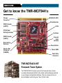
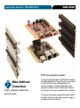
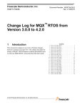
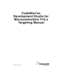
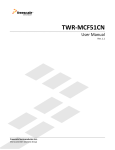
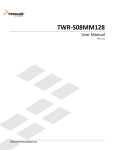
Quick Start Guide for TWR-MCF5441X
MCF5441X
MCU peripherals with
MPU performance
TOWER SYSTEM
TOWER SYSTEM
Get to know the TWR-MCF5441x
MCF5441X MPU
Primary
Connector
Potentiometer
RS232 Header
(UART0)
LEDs
RCON Boot
Setting Switches
Switches
RS232 Header
(UART4)
Interrupt
Push
Buttons
Boot Setting
Switches
Reset Button
Mini-B USB
Connector
(OSBDM)
26-pin BDM
Secondary
Connector
TWR-MCF5441X-KIT
Freescale Tower System
The TWR-MCF5441X module is part of the Freescale Tower System,
a modular development platform that enables rapid prototyping and tool
re-use through reconfigurable hardware. Take your design to the next
level and begin constructing your Tower System today.
Quick Start Guide for TWR-MCF5441X
TOWER SYSTEM
Introduction
The MCF5441X offers MCU peripherals with MPU performance,
including integrated analog, an L2 switch and dual Ethernet.
Add Linux® and MQX™ RTOS, plus Eclipse-based
CodeWarrior IDE and you’ve got a powerful development
package for network-connected industrial applications.
MPU module features:
Enablement support includes:
• MCF5441X V4 ColdFire processor with
MMU and EMAC
• Freescale Linux BSP
• Dual Ethernet with L2 Switch
• Eclipse based CodeWarrior for
Microcontrollers v10.0
• High-Speed dual-role USB
• Complimentary Freescale MQX RTOS
• Access to DDR2, NAND, serial memories
• VoIP support through audio codec
• Extensive I/Os available up to:
• IEEE® 1588 Support
2x SPIs
1x SSI
5x UARTs
1x CAN
2x I2Cs
6x PWMs
1x eSDHC
TOWER SYSTEM
How to build your Tower
STEP
1
Locate the
Elevator Modules
Each elevator module is identifiable
by its four card edge connectors.
STEP
2
Identify the
Elevator Modules
Each elevator module is either Primary
or Secondary. They are identifiable
as follows:
• Primary Elevator:
written on inside top and denoted
by white card edge connectors
• Secondary Elevator:
written on inside bottom
STEP
3
Locate Additional
Modules
Gather any additional modules that
will be used to assemble your desired
Tower System configuration.
STEP
4
Identify the Primary and
Secondary Card Edges
For each module, the words Primary and
Secondary are written along the card
edges. The primary edge is also denoted
by a white stripe.
STEP
5
Plug in Primary
Card Edge
Match the white stripe on the edge of
each module to any available connector
on the Primary Elevator and plug it in.
STEP
6
Attach Secondary
Elevator
With all desired modules connected to
the Primary Elevator, carefully attach the
Secondary Elevator onto to the secondary
card edges of each module.
Quick Start Guide for TWR-MCF5441X
TOWER SYSTEM
NOTE: First-generation modules
STEP
7
Make Additional
Connections
Plug in necessary cables and
power sources.
If using the first generation of TWR-ELEV modules,
the board labeled Functional Elevator is equivalent
to the Primary Elevator as described in the
instructions above. The board labeled Dummy
Elevator is different than the Secondary Elevator,
but will work with most assembled Tower Systems.
If using first-generation peripheral and MCU/MPU
modules, the white stripe along the outer edge of
the board will not be present.
TOWER SYSTEM
Step-by-step installation instructions
In this Quick Start Guide, you will learn how to set up the TWR-MCF5441X
module and run the Linux and MQX shell demonstrations.
STEP
1
Assemble the Required
Tower System Modules
The Linux and MQX demonstrations that
come pre-installed on the TWR-MCF5441X
require the use of the TWR-SER2. Please
assemble the TWR-MCF5441X and the
TWR-SER2 together using the TWR-ELEV
as described in the “How to build your
Tower” section of this Quick Start Guide.
STEP
2
Connect the
Serial Cable
Attach the header end of the provided
DB9 adapter cable to UART0 (J1) of the
TWR-MCF5441X. Attach the DB9 end
to a serial cable connected to the host
computer. Open a terminal window on
the host computer. Use the appropriate
COM port to establish a serial connection
with the TWR-MCF5441X.
Use the following connection settings:
Bits per second: 115200, Data bits: 8,
Parity: None, Stop bit: 1, Flow control:
None.
STEP
3
Connect the
USB Cable
Attach the provided USB A-to-Mini-B
cable between the host computer (or a
USB wall adapter) and the Mini-B (J9)
receptacle on the TWR-MCF5441X.
The USB cable will supply power to the
TWR-MCF5441X and additional
Tower System modules via the
TWR-ELEV. The connected terminal
window on the host computer should
indicate that U-Boot initialization
has started.
Quick Start Guide for TWR-MCF5441X
STEP
4
Setting the Default OS
TOWER SYSTEM
Setting the default OS to the Linux kernel:
The TWR-MCF5441X comes
preloaded with a Linux kernel and a basic
MQX shell. The Linux kernel is the default
application that U-Boot will load.
• Type “set bootcmd run jffs2boot” and
press “Enter.” Then type “save” and
press “Enter” to save this change to the
U-Boot environment variable to NAND.
To change the default OS press any key
within the connected terminal window
on the host computer within the first few
seconds of U-Boot initialization.
• Press the reset button (SW3) on the
TWR-MCF5441X to restart U-Boot and
automatically enter the Linux kernel.
The terminal will present the user with a
U-Boot prompt.
Setting the default OS to the MQX shell:
• Type “set bootcmd run mqxboot” and
press “Enter.” Then type “save” and
press “Enter” to save this change to the
U-Boot environment variable to NAND.
• Press the reset button (SW3) on the
TWR-MCF5441X to restart U-Boot and
automatically enter the MQX shell.
STEP
5
Linux Prompt Option
Refer back to Step 4 if required
to set the default OS.
U-Boot will initialize and automatically
load the preinstalled configuration of
Linux from NAND. Once the Linux boot
has completed the user is presented
with a Linux prompt. At the prompt use
the “help” command to explore available
commands.
TOWER SYSTEM
STEP
6
MQX Shell Option
Refer back to Step 4 if required
to set the default OS.
U-Boot will initialize and automatically
load the precompiled basic MQX shell
from NAND. Once the MQX shell has
completely loaded the user is presented
with an MQX prompt. At the prompt use
to “help” command to explore available
commands.
STEP
7
Install Additional
Software and Tools
• Install CodeWarrior Development
Studio for Microcontrollers v10.0
(Professional Edition—30 day license)
• Visit freescale.com/codewarrior for
any additional updates or patches
• Install Freescale MQX RTOS v3.6
• Visit freescale.com/mqx for the
required v3.6.x patch to support
TWR-MCF5441X
STEP
Learn More About
the MCF5441X, MQX,
and the MCF5441X Linux
BSP Software
8
Read the release notes and
documentation located on the provided
DVD. Visit freescale.com/tower for
additional and updated documents,
labs and demonstration videos, including
demonstrations featuring IEEE 1588
precise time synchronization and
motor control applications.
Refer to the following labs for more
hands-on experience with the
TWR-MCF5441X (note some labs
require the use of the TWR-SER2):
• Lab 1: MQX—Dual Web Server using
Freescale MQX RTOS
• Lab 2: MQX—Telnet to Serial Bridge
Using Optional UART Ports
• Lab 3: Linux—Web Server Using
Linux OS
• Lab 4: Linux—Getting Started with
RTC and Telnet
Quick Start Guide for TWR-MCF5441X
STEP
9
Explore Additional
Linux BSP Features
Refer to the included Linux BSP release
included on the provided DVD for
additional Linux configurations and
instructions on recompiling and loading
the Linux kernel.
Visit freescale.com/tower for any
additional updates/patches to the
TWR-MCF5441X Linux BSP.
STEP
10 Explore Additional
MQX Projects
The included lab tutorials represent
completed end applications utilizing
many of the microcontroller resources.
To begin your application, there are
simple MQX templates located under
“C:\Program Files\Freescale\Freescale
MQX 3.6\mqx\examples”
TOWER SYSTEM
For more information on Tower System
controllers and peripheral modules,
visit freescale.com/tower. To become
a member of the online Tower Geeks
community, visit towergeeks.org.
TOWER SYSTEM
TWR-MCF5441X Jumper Options
The following is a list of all the jumper options. The *default* installed jumper settings are shown in bold
with asterisks.
Jumper
SW1
Option
RCON Settings
Setting
Description
DIP 1
FB_AD0
*On*
DIP 2
FB_AD1
*On*
PLL Disabled
Off
PLL Enabled
DIP 3
FB_AD2
*On*
Crystal Oscillator Mode
Off
Oscillator Bypass Mode
DIP 4
FB_AD3
*On*
External Memory Bus implements select as FB_ALE
Off
External Memory Bus implements select as FB_TS_b
DIP 5/6
FB_AD[5:4]
DIP 7/8
FB_AD[3:2]
Off
J2
Clock Select
2-3
Boot from External Memory Bus (Flexbus)
On/On
Boot Port Size: 32-bit data (32-bit muxed address)
On/Off
Boot Port Size: 8-bit (24-bit non-muxed address)
*Off/xx*
Boot Port Size: 16-bit (16-bit non-muxed address)
*On/On*
PLL Multiplier: Fvco = 10 x Fref
On/Off
PLL Multiplier: Fvco = 15 x Fref
Off/On
PLL Multiplier: Fvco = 16 x Fref
Off/Off
*1-2*
Boot from NAND Flash
PLL Multiplier: Fvco = 20 x Fref
Select external clock source (Required for RMII)
Select on-board 25 MHz clock source
Quick Start Guide for TWR-MCF5441X
Jumper
Option
Boot Mode
J5
BOOTMOD[1:0]
Setting
*3-4*
JTAG/BDM
Select
J8
Debug Clock
Select
J10
JM60
BootMode
Description
Shunt for BOOTMOD[1]=0 / Un-shunt for BOOTMOD[1]=1
1-2
Shunt for BOOTMOD[0]=0 / Un-shunt for BOOTMOD[0]=1
00
Boot from External Memory Bus (Flexbus) using default settings
*01*
1x
J6
TOWER SYSTEM
1-2
*1-2*
Override default settings and use RCON (SW1) to decide boot source
Override default settings and boot from serial boot facility with
option to load to and boot from RAM. If not booting from RAM,
RCON decides boot source.
Shunt to enable BDM / Un-shunt to enable JTAG
Selects BDM PSTCLK
2-3
Selects JTAG TCLK
1-2
Shunt to enable optional boot mode of MC9S08JM60
For additional configurations using Cut-Trace pads refer to the TWR-MCF5441X User Manual
TOWER SYSTEM
Learn more at freescale.com/tower.
Freescale, the Freescale logo and CodeWarrior are trademarks or
registered trademarks of Freescale Semiconductor, Inc. in the U.S. and
other countries. All other product or service names are the property of
their respective owners. © Freescale Semiconductor, Inc. 2010.
Doc Number: TWRMCF5441XQSG / REV 0
Agile Number: 926-26131 / REV A