1
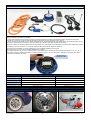
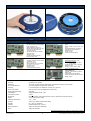
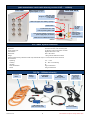
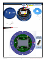
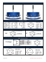
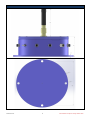
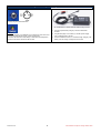
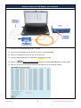
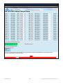
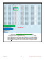
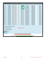
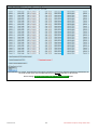
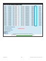
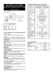
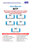
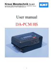
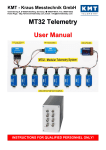
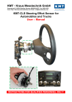
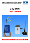
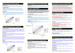
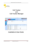
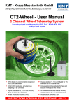
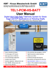
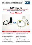
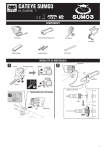
KMT - Kraus Messtechnik GmbH Gewerbering 9, D-83624 Otterfing, Germany, 08024-48737, Fax. 08024-5532 Home Page http://www.kmt-telemetry.com, Email: [email protected] User Manual CTP8-Rotate 8 (4) channel telemetry for rotating applications like wheels or rotors, high signal bandwidth, 16bit, software programmable INSTRUCTIONS FOR QUALIFIED PERSONNEL ONLY! Inputs for STG, TH-K, ICP or VOLT Battery power up to 10h Simultaneous sampling Radio telemetry transmission 16 bit resolution Output analog +/- 10V Software programmable Digital data interface to PC (option) Signal bandwidth: up to 24kHz (4 CH) Waterproofed ENC housing (IP65) General functions: The CTP8-Rotate is a 8-channel telemetry system for rotating applications with integrated signal conditioning for sensor signals, wireless digital transmission and analog reproduction. In the encoder/transmitter unit the sensor signals are conditioned, filtered (anti-aliasing) and digitized (16-bit). Simultaneous sampling is provided for all channels. Finally the PCM encoded data is transmitted via radio frequencies to the receiver. Various configurations of different sensor modules are available incl. signal conditioning for strain gages (STG), thermocouples type K (TH-K), ICP sensors, potentiometer sensors (POT) and also voltage inputs. Mixed configuration available (2-CH-steps). All sensor modules are software programmable via LAN-Adapter. The LAN-Adapter has an integrated web interface and enables easy access! The stationary receiver provides 8x +/-10V analog outputs via BNC socket (option: digital PC interface). The analog signal bandwidth is 0-750 Hz (320kbit) and up to 0-12000Hz (5000kbit) for 8 channels. On request is a 4 CH version with 0-24000Hz (5000kbit) also available The measurement accuracy is <±0.2 % (without sensor). The CTP8-Rotate is specified for operational temperatures from -20° C to +70° C. The maximum distance between transmitter and receiving antenna is approx. 10-20 m (30-60 feet) – depending on the application! Mixed configuration available (2-CH-steps). Specify CTP-xx modules at order!! Frequency table Cut off frequency from anit-aliasing filter (-3dB) and sampling rate (see red) Bit rate 4 CH (Option) 8 CH. 50000kbit 24000 Hz (62500 Hz) 12000 Hz (31250 Hz) 2500kbit 12000 Hz (31250 Hz) 6000 Hz (15625 Hz) 1250kbit 6000 Hz (15625Hz) 3000 Hz (7812.5 Hz) 625kibt 3000 Hz (7812.5 Hz) 1500 Hz (3906.25 Hz) 312.5kbit 1500 Hz (3906.25 Hz) 750 Hz (1953.125 Hz) CAR wheel Version 2013-10 Different applications: Truck wheel 2 Helicopter rotor Technical Data are subject to change without notice! CTP8-Rotate Transmitting Unit Technical Data (Encoder) Encoder in IP65 Aluminum housing Encoder inside CTP acquisition modules (rotor side) CTP-STG-V3 Acquisition module for 2 strain gages Full, half and quarter bridge (≥350) Fixed excitation 4V DC Offset calibration by auto zero Manual offset shifting after auto zero Gain: 125-250-500-1000-2000 Test shunt-cal step Signal bandwidth 0Hz to 24000Hz* Resolution 16bit Accuracy <0.2% Current consumption with full bridge 350 ohm 75mA ® CTP-VOLT-V3 Acquisition module for 2x high level inputs Range: ±0,625V, ± 1,25V, ±2,5V, ± 5V, ±10V Signal bandwidth 0Hz to 24000Hz* (*see table of cut-off-frequency) Resolution 16bit Accuracy <0.2% Current consumption 60mA - CTP-ICP -V3 Acquisition module for 2 ICP sensors Current EXC. 4mA Gain: 1-2-4-8-16-32 Signal bandwidth 3 Hz to 24000Hz* CTP-TH-K-V3 Acquisition module for 2x TH-K Inputs galvanic isolated Range -50 to 1000°C, -50 to 500°C or -50 to 250°C Cut-off filter 30Hz (more on request) Resolution 16bit Accuracy: 0.2% at 1000°C range Current consumption 110mA (*see table of cut-off-frequency) Resolution 16bit Accuracy <0.2% Current consumption 100mA CTP-CONTROL-V3 Controller 1- 32 acquisition modules Output: PCM Programmable via LAN adapter Current consumption 40mA, with LANadapter 140mA System Parameters ENCODER: Channels: 8 (optional 4 on request) Resolution: 16 bit A/D converter with anti-aliasing filter, simultaneous sampling of all channels Line-of-sight distance: up to 20m (depends of application and bit rate) Powering: Li Ion Accumulator 7.2V 4600mAh, capacity up to 10 hours Power consumption: 400 mA using 8x STG full bridge sensors 350 Ohms Analog signal bandwidth: See table Transmission: Digital PCM Miller format - FSK Transmission Power: 10mW! Dimensions: Diameter 145mm, bottom plate diameter 175mm, height 62mm (without antenna) Weight: 1.3 kg without sensor cables Operating temperature: - 20 … +70°C Housing: Aluminum anodized, waterproofed (IP65) Humidity: 20 ... 80% no condensing Vibration: 5g Mil Standard 810C, Curve C Static acceleration: 100g in all directions, 3000 RPM Shock: 200g in all directions Technical specifications are subject to change without notice! Version 2013-10 3 Technical Data are subject to change without notice! CTP-DEC8 Receiver unit for max 8 Channels output BNC (radio transmission version with diversity receiver 312.5 … 1250kbit) Front view Rear side view BNC socket for analog signal outputs 1 … 8 Auto Zero LED Bright on, if analog output is over 60mV LED on at approx. 20% battery capacity! Power Switch HF –Field strength display Transmission error LED Fuse of powering defect LED SMA antenna connector with active LED of antenna (diversity) 7-pole female TUCHEL connector for power supply input (10–30V DC) PCM out for IP-LAN-Interface (Opt.) (Option) CTP –DEC8 System Parameters: Channel: 8 x +/-10V analog outputs BNC socket Resolution: 16 bit D/A converter, with smoothing filter Power supply input: 10-30 VDC, power consumption <24 Watt Transmission: Digital PCM Format – FSK, Dimensions: 205 x 105 x 65mm Weight: 1.25 kg without cables and antenna Overall system accuracy between encoder input and decoder output: +/-0.25% without sensor influences Environmental Operating: -20 … +70°C Humidity: 20 ... 80% not condensing Vibration: 5g Static acceleration: 10g in all directions Shock: 100g in all directions SET of CTP8-Rotate 315.5k…1250kibt telemetry 8x Sensor cables Battery Charger CTP8-Rotate ENCODER LAN Adapter with LAN cross over cable Version 2013-10 4 CTP8DECODER 2x receiving Antennas With diversity receiver with 4m cable (longer on request) DC power Cable for CTP-DEC Technical Data are subject to change without notice! CTP8-Rotate Encoder for 8 channels – Modules place Tx Radio transmitter CH 1/2 CTP-Acquisition modules - 2 channels on each 1/2 3/4 5/6 7/8 CH 3/4 CH 3/4 CH 5/6 Controller If not all 4 CTP modules plugged, a BUS-PLUG must plug on empty slot! Otherwise the digital bus between is open and system don’t work!! Version 2013-10 5 Technical Data are subject to change without notice! CTP8-Rotate Encoder – Pin connection Strain gage connection VOLT connection ICP connection Setup connection PWR – Powering connection Setup connection Version 2013-10 Charger 6 Technical Data are subject to change without notice! CTP8-Rotate Encoder – Dimensions Version 2013-10 7 Technical Data are subject to change without notice! Li Ion re-chargeable battery with charger unit for CTP8-Rotate Charge plug at CTP8-Rotate ENC CT-CHARGER for CTP8-Rotate with 500mA charge current Attention: Li Ion Accumulator 7.2V 4600mAh has a capacity for about 10h hours. If the green LED indicator is ON, system is power ON If the red LED indicator is ON, battery is about 80% discharged and the device will switch off after 30-60 minutes! Version 2013-10 8 1. Plug the 3-pole socket (charger) in to the CTP8-Rotate encoder. 2. Plug banana plugs on to a battery or AC/DC power supply with a voltage range of 10-30V, 3. Press and hold the switch for 1 second to begin charging. The battery will now charge. Charge time 9-10 hours! Technical Data are subject to change without notice! CTP ENCODER (example with CTP16-ENC) Software setup via LAN-Adapter and notebook LAN crossover cable Power IN 7-30V DC LAN Adapter only for SETUP 1) Power the CTP ENCODER with power 7-30 VDC 2) Connect the LAN-Adapter on the SETUP connector ov CTP ENCODER 3) Adjust your notebook to manual on e.g. IP 192.168.0.20 4) Connect LAN-Adapter with your notebook via cross-over LAN cable 5) Open e.g. Microsoft Internet Browser and enter IP address 192.168.0.110 of LAN-Adapter 6) Now you get access on the web-interface and can adjust the CTP acquisition module Version 2013-10 9 Technical Data are subject to change without notice! MTP-CONTROL V3 - Software setup DOWNLOAD parameters for device First you can download the stored parameters from the acquisition modules via LAN adapter from the controller module . All connected acquisition modules will detect! Caution: Never use the refresh button Version 2013-10 on your browser; otherwise the parameters of you browser cash will upload to the MTP-STG!° 10 Technical Data are subject to change without notice! BRIDGE setting STG Select full-, half- or quarter-bridge by popup window Execute through “Upload Parameters to MT-PRO and perform Autozero” button If you want test your bridge, you can execute the function Test-Shunt Resistor for 20 sec. button In this case all STG channels get a shunt-cal step of about 80% of the from measuring range at GAIN 2000 In this case all STG channels get a shunt-cal step of about 40% of the from measuring range at GAIN 1000 In this case all STG channels get a shunt-cal step of about 20% of the from measuring range at GAIN 500 In this case all STG channels get a shunt-cal step of about 10% of the from measuring range at GAIN 250 In this case all STG channels get a shunt-cal step of about 5% of the from measuring range at GAIN 125 Version 2013-10 11 Technical Data are subject to change without notice! GAIN setting STG Select gain of 125-250-500-1000 or 2000 by popup window After change the gain you must make a new autozero!! Execute through “Upload Parameters to MT-PRO and perform Autozero” button Version 2013-10 12 Technical Data are subject to change without notice! AutoZero setting STG Select Auto-Zero per channel. The Auto-Zero function will be executed only one time per upload the parameters to MTP-STG! It will be stored also after power off in the MTP-STG until you make a new Auto-Zero on this channel! Execute through “Upload Parameters to MT-PRO and perform Autozero” button Version 2013-10 13 Technical Data are subject to change without notice! Manual Offset shifting after AutoZero After AutoZero you can shift (if necessary) the offset in +/-2000 steps Execute through “Upload Parameters to MT-PRO and perform Autozero” button Version 2013-10 14 Technical Data are subject to change without notice!