1
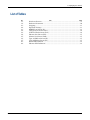
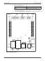
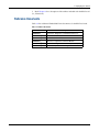
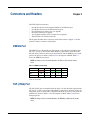
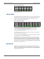
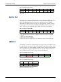
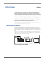
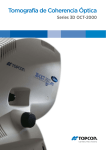
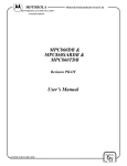
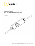
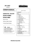
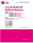
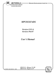
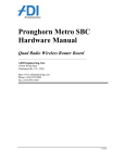
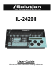
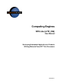
Computing Engines
RPX Lite (LITE_DW)
User Manual
Developing Embedded Applications & Products
Utilizing Motorola PowerPC™ 8xx Processors
700M0006RA0
2
700M0006RA0
Computing Engines, RPX Lite
Notice
This manual in whole or in part, is to be considered the intellectual property of
Embedded Planet. The manual and all information explained and derived there
from are protected by the license to which you agreed upon opening this package.
This document contains confidential information and is intended for the sole
purpose of the end user to develop applications on the RPX Lite product offered
by Embedded Planet, LLC. Neither the document, nor reproductions of it, nor
information derived from it is to be given to others, nor used for any other
purpose other than for RPX Lite applications. No use is to be made of it which is
or may be injurious to Embedded Planet, LLC and no use is to be made of it other
than for RPX Lite applications.
Trademarks
Embedded Planet, PlanetTrack, Linux Planet, Blue Planet, RPX Lite, and RPX
LICC are trademarks or registered trademarks of Embedded Planet.
PowerPC is a trademark of International Business Machines.
All other names and trademarks are the property of their respective owners.
700M0006RA0
3
Computing Engines, RPX Lite
4
700M0006RA0
Computing Engines, RPX Lite
Contents
Chapter 1 Introduction .......................................................................................................... 7
Functions .........................................................................................................................................7
How to Use This Manual ..............................................................................................................9
Reference Documents ..................................................................................................................10
Chapter 2 Setup ................................................................................................................... 11
Strapping .......................................................................................................................................11
Dipswitch ......................................................................................................................................11
Chapter 3 Connectors and Headers ................................................................................... 13
DEBUG Port ..................................................................................................................................13
TAP (JTAG) Port ...........................................................................................................................13
UTILITY Header ...........................................................................................................................14
Ethernet Port .................................................................................................................................14
Monitor Port ..................................................................................................................................15
USB Port .........................................................................................................................................15
Power Connector ..........................................................................................................................16
Power Options .......................................................................................................................16
Considerations .......................................................................................................................16
Bus and I/O Interface Expansion Connectors .........................................................................16
Chapter 4 Operation ............................................................................................................ 19
Board LEDs ...................................................................................................................................19
Ethernet Port LEDs ......................................................................................................................19
Chapter 5 RPXL Versus LITE .............................................................................................. 21
Chapter 6 Utility Software ................................................................................................... 23
RS-232 Cable Connections ..........................................................................................................23
User Applications Information ..................................................................................................24
List of Figures
No.
1-1.
1-2.
6-1.
6-2.
700M0006RA0
Title
Page
RPX Lite Board - Top View ..............................................................................................8
RPX Lite Board - Bottom View........................................................................................9
RS-232 Cable Connections - Null Modem...................................................................23
RS-232 Cable Connections - RJ-45 to DB9 Cable ........................................................24
5
Computing Engines, RPX Lite
List of Tables
No.
1-1.
1-2.
2-1.
2-2.
3-1.
3-2.
3-3.
3-4.
3-5.
3-6.
3-7.
4-1.
4-2.
6
Title
Page
Hardware Features ...........................................................................................................7
Reference Documents.....................................................................................................10
Strapping..........................................................................................................................11
Dipswitch Settings ..........................................................................................................11
DEBUG Port Pinout (P6)................................................................................................13
TAP (JTAG) Port Pinout (P7) ........................................................................................14
UTILITY Header Pinout (P14) ......................................................................................14
Ethernet Port Pinout (PE3) ............................................................................................15
Monitor Port Pinout (PM3)............................................................................................15
Type A USB Port Pinout (P4) ........................................................................................15
Type B USB Port Pinout (P5).........................................................................................15
Board LED Definition.....................................................................................................19
Ethernet LED Definitions ..............................................................................................19
700M0006RA0
Introduction
Chapter 1
The RPX Lite (LITE_DW) is a highly integrated single-board computer (SBC)
based on the Motorola MPC850 and MPC823. The MPC850 versions are targeted
for the telecommunications industries, while the MPC823 version is targeted for
the industrial controls market. Support is available from Embedded Planet or
from third-party vendors for several commonly used real-time operating systems
(RTOS).
The RPX Lite is in a PC104 board form factor (Figs. 1-1 and 1-2). It does not contain PC104 (ISA) or PC104+ (PCI) functionality, but rather adheres to the mechanical specifications of the PC104 standard. For PC104 (ISA) or PC104+ (PCI)
requirements, refer to the RPXC User Manual.
Functions
The functions included on the RPX Lite are listed in Table 1-1. For programming
information, refer to the RPX Lite Programmer’s Firmware Manual.
Table 1-1. Hardware Features
Entity
Function
Processor
MPC850 (SR, DE, etc.) or MPC823E
SDRAM
16, 32, or 64 Mbytes
FLASH
2, 4, 8, or 16 Mbytes
NVRAM/RTC
0, 32, 128, 512 Kbytes
Ethernet port
SCC2 - 10BaseT (RJ-45)
Monitor port
SMC1 - 3-wire RS-232 (RJ-45)
Serial EEPROM
I2C
Serial temperature and thermal monitor I2C
Debug
Development port header for BMD
TAP
TAP header for test and JTAG
PCMCIA
Single slot - Type I, II, or III
USB
Type A or type B connector
Dipswitch
4-position slide switch read via status register
LEDs
Two user-programmable via control register
1
700M0006RA0
Bus expansion receptacle
Processor bus interface expansion receptacle
I/O expansion receptacle1
Processor I/O interface expansion receptacle
5 VDC supply
(optional 3.3 VDC supply)
Single power supply source for board
(board draws 1A maximum)
7
Chapter 1 - Introduction
Computing Engines, RPX Lite
Table 1-1. Hardware Features (continued)
Entity
Function
BCSR2
Control and status register (BCSR0, 1, 2, 3)
NOTES:
1. The expansion receptacles allow for daughter cards supporting such functions as CAN, ARCNET,
T1/E1, xDSL, PCI via PC104+, etc.
2. Refer to the RPX Lite Programmer’s Firmware Manual for a description of the BCSR registers.
BUS
EXPANSION
UTILITY
HEADER
DEBUG
PORT
TAP
PORT
I/O
EXPANSION
D
P14
T
P6
P7
TP1
A1
B1
A1
TP2
B1
P2
P1
ETH
RO5R
PE3
ROB3 ROA3
RG1
P5
P4
MON
PM3
RO6
P16
CR14
MONITOR PORT
(SMC1)
ETHERNET PORT
(SCC2)
USB A
USB B
5 VDC
T00011A
Figure 1-1. RPX Lite Board - Top View
8
700M0006RA0
Computing Engines, RPX Lite
Chapter 1 - Introduction
PCMCIA
P10
RNB12
2
3
RO2J
1
ON
4
RNA12
SW1
RO1
CR6
CR1
RO2D
CR3
CR8
CR2
T00019A
Figure 1-2. RPX Lite Board - Bottom View
How to Use This Manual
1. Refer to Chapter 2 for setup information including strappings and dipswitch
settings.
2. Refer to Chapter 3 for a description of the connectors and headers available
on the RPX board.
3. Refer to Chapter 4 for a description of the LED indications for the RPX board
and Ethernet port.
4. Read Chapter 5 for an explanation of the differences between an RPXL_CW
and LITE_DW board.
700M0006RA0
9
Computing Engines, RPX Lite
5. Read Chapter 6 for a description of the utilities included with the RPX board
(i.e., PlanetCore).
Reference Documents
Table 1-2 lists additional Embedded Planet documents for the RPX Lite board.
Table 1-2. Reference Documents
Document Number
10
Description
700M0002R__
PlanetCore, Diagnostics and Utilities (Release 1)
700M0003R__
PlanetCore, Boot Loader
700M0004R__
PlanetCore, Flash Burner
700M0007R__
RPX Lite, Programmer’s Firmware Manual
700M0014R__
PlanetCore, Diagnostics and Utilities (Release 2)
700M0028R__
RPX Lite, Expansion Card Design Guidelines
700M0006RA0
Setup
Chapter 2
This chapter describes the various strappings and dipswitch settings that setup
the LITE_DW board for operation. The straps are zero ohm, surface-mount resistors. The dipswitch has four positions.
Strapping
Table 2-1 describes the various strap settings; refer to Figures 1-1 and 1-2 for the
locations of the straps.
Table 2-1. Strapping
Purpose
Strap
Function
DEBUG
RO2D
Debug port on processor active (P6)
JTAG
RO2J
JTAG chain active (P7)
5 VDC monitor
RO5R
Populated = 5 VDC supply monitored for an out of tolerance condition.
Not populated = 5 VDC supply not monitored for an out of tolerance condition.
Earth ground
RO6
Populated = EARTH_GND connected to digital ground at one point.
Not populated = EARTH_GND not connected to digital ground.
SMC1
ROA3
RS-232 transceiver drives the DTR# true all the time (5 VDC minimum at 1.67mA).
ROB3
5 VDC rail drives the DTR# signal all the time (for powering IR keyboards).
Dipswitch
The four-pole dipswitch (SW1) located on the board is readable via the onboard
status register. The switch is intended for use by specific customer applications.
Table 2-2 describes the switch settings; refer to Figure 1-2 for the location of the
dipswitch.
Table 2-2. Dipswitch (SW1) Settings
Pole Positions
Function
4321
D(27:24)
0000 or 1111
Normal operating mode
0001
Reserved for manufacture test
0010
Reserved for fallback mode
0011 through 1110
User specified
NOTE:
down = on = closed position will read back a logic 0 in the status register.
up = off = open position will read back a logic 1 in the status register.
700M0006RA0
11
Computing Engines, RPX Lite
12
700M0006RA0
Connectors and Headers
Chapter 3
The LITE_DW board contains:
One RJ-45 connector with integrated LEDs for the Ethernet port.
One RJ-45 connector for the RS-232 monitor port.
One USB connector (either type A or Type B).
One barrel connector for power.
Two daughter card bus and I/O expansion receptacles.
Three headers for auxiliary functions.
•
•
•
•
•
•
This chapter describes these connectors and headers. Refer to Figure 1-1 for the
locations of these connectors and headers.
DEBUG Port
The DEBUG port is identified with the letter D on the silkscreen (middle header
P6). It is a 2 × 5 (0.1 × 0.1) header. When RO2D is populated to select this mode,
the TAP (JTAG) chain on the board is disconnected, and the DEBUG port is dedicated to the processor. Refer to Table 2-1 for a description of RO2D. Table 3-1
shows the DEBUG port pinout.
NOTE: No mating connector should be attached to the TAP port (P7) when this mode is
active.
Table 3-1. DEBUG Port Pinout (P6)
Pin
Function
Pin
Function
9
7
5
3
1
+3.3V
HRST#
GND
GND
FRZ
10
8
6
4
2
DSDO
DSDI
FRZ
DSCK
SRST#
NOTE: Pin numbering 1 through 10 as shown in table is when looking
down onto the header.
TAP (JTAG) Port
The TAP (JTAG) port is identified with the letter T on the silkscreen (right header
P7). It is a 2 × 5 (0.1 × 0.1) header. When RO2J is populated to select this mode, the
TAP (JTAG) chain on the board is completed. The chain is processor first, then the
CPLD device. Refer to Table 2-1 for a description of RO2J. Table 3-2 shows the
TAP port pinout.
NOTE: No mating connector should be attached to the DEBUG port (P6) when this mode is
active.
700M0006RA0
13
Chapter 3 - Connectors and Headers
Computing Engines, RPX Lite
Table 3-2. TAP (JTAG) Port Pinout (P7)
Pin
Function
Pin
Function
9
7
5
3
1
TCK
TMS
TDO
TDI
TRST#
10
8
6
4
2
GND
GND
+3.3V
GND
GND
NOTE: Pin numbering 1 through 10 as shown in table is when looking down onto the header.
UTILITY Header
The UTILITY header is the left header (P14). It is a 2 × 8 (0.1 × 0.1) header. The utility header is used to allow for external connections. Three types of reset signals
can be connected to the header: hard reset, soft reset, and power on reset.
Table 3-3 shows the UTILITY header pinout.
Table 3-3. UTILITY Header Pinout (P14)
Pin
Function
Pin
Function
15
13
11
9
7
5
EBAT
—
+12.0V
—
16
14
12
10
8
6
GND
GND
GND
GND
GND
GND
PFIRQ0# SRST#
3
1
POR#
HRST#
4
2
GND
GND
NOTES:
1. Pin numbering 1 through 16 as shown in table is when looking down onto the header.
2. Signals HRST#, POR#, and SRST# must be open drain or open collector type signals.
3. Pins 1, 3, 5, and 7 are input signals (digital 3.3 VDC signals).
4. Pins 11 and 15 are input voltage signals (voltages that can be supplied to these pins).
5. Pins 9 and 13 are currently no connects.
The PFIRQ0# signal is routed to interrupt level 0 on the processor and could be
used as a Power Fail Interrupt signal.
The 12.0 VDC signal is used for PCMCIA cards that require 12.0 VDC. 12.0 VDC is
not used anywhere else on the LITE_DW board.
The EBAT signal is for connecting an external battery to back up the real-time
clock and keep alive power circuits inside the processor. The onboard NVRAM/
RTC has its own battery and is not associated with the EBAT signal. The EBAT
signal does not have any connection to the supplies powering and operating the
board. When no external battery is connected to the EBAT signal, a jumper should
be connected across pins 15 and 16.
Ethernet Port
The Ethernet port is identified by the reference designator PE3 and the letters
ETH. It is a shielded RJ-45 jack with integrated LEDs. Table 3-4 shows the 10BaseT
RJ-45 jack pinout. The RJ-45 connector is shielded and tied to EARTH GROUND.
The Ethernet port is from SCC2.
14
700M0006RA0
Computing Engines, RPX Lite
Chapter 3 - Connectors and Headers
Table 3-4. Ethernet Port Pinout (PE3)
Pin
8
7
Function
6
5
4
RXD-
3
2
1
RXD+
TXD-
TXD+
NOTE: Pin numbering 8 down to 1 is from left to right when looking into the RJ-45 jack (locking
tab on top).
Monitor Port
The RS-232 monitor port is identified by the reference designator PM3 and the letters MON. It is a shielded RJ-45 jack. Table 3-5 shows the RS-232 RJ-45 jack
pinout. The RS-232 Monitor Port connector is shielded and tied to EARTH
GROUND. The signals listed in the table are surge protected, with the transient
voltage suppressors connected to EARTH GROUND. The monitor port is from
SMC1. Support of the handshake signals RTS# and CTS# is via the BCSR.
Table 3-5. Monitor Port Pinout (PM3)
Pin
1
2
Function
3
4
5
6
7
8
DTR#
GND
RXD
TXD
CTS#
RTS#
NOTES:
1. Pin numbering 1 through 8 is from left to right when looking into the RJ-45 Jack (locking tab
on bottom).
2. RTS# can be driven by the BCSR.
3. CTS# can be received by the BCSR.
4. DTR# can be driven, via strapping option, by the RTS# signal or by the system 5 VDC supply.
USB Port
The USB port is either P4 or P5 depending on the type of connector installed: Type
A or Type B. Only one type of connector is installed on the board. The Type A and
Type B connectors are dual-footprints on the PCB, and as such, the type of connector is a manufacturing option specified at the time of order. Table 3-6 shows the
Type A USB port pinout; Table 3-7 shows the Type B USB pinout.
Table 3-6. Type A USB Port Pinout (P4)
Pin
Function
1
2
3
4
+5.0V
DATA-
DATA+
GND
NOTE: Pin numbering 1 through 4 is from left to right when looking into the connector.
Table 3-7. Type B USB Port Pinout (P5)
Pin
Function
Pin
Function
2
DATA-
1
+5.0V
3
DATA+
4
GND
NOTE: Pin numbering 1 through 4 as shown in table is when looking into the connector.
700M0006RA0
15
Chapter 3 - Connectors and Headers
Computing Engines, RPX Lite
Power Connector
The power connector is a barrel type connector. The specifications for the mating
connector are as follows:
Inner diameter = 2.5mm (0.100 inches)
Outer diameter = 5.5mm (0.218 inches)
Barrel Length >/= 9.5mm (0.375 inches)
Outer shell is GND
Inner shell is +5.0V
Power Options
Two options exist for powering the LITE_DW board:
•
5 VDC can be supplied through either the barrel connector or through the
expansion receptacles via an Expansion Card.
•
3.3 VDC can be supplied through either the barrel connector or through the
expansion receptacles via an Expansion Card.
NOTE: The option selected must be specified at time of ordering the product because the
option selected is assembly dependent.
If the 3.3 VDC option is selected, then the following limitations apply:
1. The USB VCC rail on the USB connector cannot be powered with 5 VDC from
the LITE_DW board, since 5 VDC is not available on the board. Another source
must be used to power the 5 VDC line on the connector side. Aside from the
5 VDC supply issue on the USB connector, USB functionality is still supported.
2. 5 VDC PCMCIA cards are not supported, since 5 VDC is not available on the
LITE_DW board.
Considerations
The DC supply must be a regulated +5 VDC, ±5% supply when using the 5 VDC
power option. The 3.3 VDC power option requires a 3.2 to 3.4 VDC supply.
The LITE_DW board itself, fully configured but with no expansion cards or PCMCIA cards, draws 1.0 A maximum at VCC = 4.75 VDC to 5.25V DC, T = 0oC-70oC.
Bus and I/O Interface Expansion Connectors
The processor bus expansion receptacle is the connector strip on the left side identified as P1. The processor I/O expansion receptacle is the connector strip on the
right side identified as P2. They are 2 × 60 (B8 Type) receptacles.
This interface allows daughters cards to be designed and interfaced to the
LITE_DW board. All required signals are routed to the receptacle to allow for
daughter cards that require the processor interface. Pins A1 (on left) and B1 (on
right) are identified on the PCB.
The connector type chosen allows for variable stacking heights and is an 8 mm
pitch connector. The standard LITE_DW product board to board mating distance
is 16 mm. Available stacking heights range from 4.5 mm to 20 mm. The receptacle
part number used on the standard product is AMP 5-179010-5. The standard mat-
16
700M0006RA0
Computing Engines, RPX Lite
Chapter 3 - Connectors and Headers
ing connector (plug) is AMP 179031-5, which would be used on Expansion Card
designs.
For signal loading considerations, refer to the Expansion Card Design Guidelines
manual.
Important
The bus expansion receptacle (P1) or interface must be a 3.3 VDC only type of
interface (the I/O is not 5.0V I/O tolerant).
The I/O expansion receptacle (part of P2) or interface is currently 5 VDC tolerant,
but indications from the Motorola Semiconductor Sector claim that future processors will not be 5.0 VDC tolerant on I/O pins. Therefore, it is highly recommended
that I/O interfaces on daughter cards be designed for true 3.3 VDC operation.
For the pinout of the P1 and P2 receptacles, refer to the pinouts document associated with the board. Pages 1 through 3 of the pinout file are for the RPXC and
CLLF (860/821 based) and pages 4 and 5 are for the LITE_DW (850/823 based).
700M0006RA0
17
Computing Engines, RPX Lite
18
700M0006RA0
Operation
Chapter 4
This chapter describes the LED indications.
Board LEDs
Table 4-1 describes the indications for the RPX board LEDs; refer to Figures 1-1
and 1-2 for the locations of the LEDs.
Table 4-1. Board LED Definition
LED
LED Definition When On
Color
CR1
3.3 VDC power applied
Green
CR2
Status LED4
Red
CR3
Status LED5
Red
CR6
Processor activity (BB# signal)
Green
CR8
Processor hard reset active
Red
CR14
5 VDC power applied
Green
NOTE: CR14 is on top side of the board and all others on the
bottom side.
Ethernet Port LEDs
Table 4-2 describes the indications given by the Ethernet port LEDs. These LEDs
are integrated into the Ethernet port (ETH).
Table 4-2. Ethernet LED Definitions
State
Indication
Left LED
Right LED
Off
Link integrity bad
No RXD or TXD activity
Yellow
Link integrity good and
10Mbps Ethernet
RXD or TXD activity and
half-duplex Ethernet
Green
Link integrity good and
100Mbps Ethernet1
RXD or TXD activity and
full-duplex Ethernet
NOTE:
1. 100Mbps Ethernet is currently not supported.
700M0006RA0
19
Computing Engines, RPX Lite
20
700M0006RA0
RPXL Versus LITE
Chapter 5
This chapter explains the differences between the previous RPXL_CW board and
the LITE_DW board. The differences and changes are:
DRAM
Replace 16 Mbytes of EDO DRAM with 16, 32, or 64 Mbytes of SDRAM.
SMC1
•
Control provided for the RTS# and CTS# signals for handshaking purposes.
•
DTR# can be driven by RTS# or the system 5 VDC supply.
•
RTS# is in BCSR1.8.
•
CTS# is in BCSR1.9.
•
DTR# via strapping option.
•
RPXL_CW requires bit swapping to support the NVRAM/RTC.
•
RPXL_CW does not support IRQ capability from the NVRAM/RTC.
•
IRQ from the NVRAM/RTC in BCSR3.30 and can be enabled on IRQ4# via
BCSR2.23
NVRAM/RTC
Ethernet LEDs
USB
Board mounted LEDs for the Ethernet circuit are removed and included in the
RJ-45 connector.
Host mode USB supported via the recommended Motorola external hardware fix.
•
P2 Expansion
BCSR2.21 enables the required external USB host mode hardware support.
Modification to P2 expansion pinout:
•
RPXL_CW brought up miscellaneous voltages on the P2 expansion connector.
•
LITE_DW replaces the miscellaneous voltages on P2 with the AT[0..3] signals
as follows:
P2.A52 was 12V, is AT2
P2.B51 was 12V, is AT3
P2.A55 was VP, is AT0
P2.B54 was VM, is AT1
•
700M0006RA0
Expansion cards that require miscellaneous supply voltages must provide a
means for connecting that supply directly to the expansion card.
21
Computing Engines, RPX Lite
22
700M0006RA0
Utility Software
Chapter 6
The LITE_DW board, in its simplest form, is shipped with Embedded Planet
boot-up and diagnostic software known as PlanetCore. This code verifies the
integrity of the hardware, allows configuration changes, and allows downloading
of user code. Additional functionality will be added to this code, and as the additional functionality becomes available, the program will be updated, and is available from Embedded Planet. Upgrades are provided as files containing Motorola
s-records. The s-record data is a program which is downloaded to DRAM either
using the monitor serial port and a terminal emulation program, or using the
Ethernet port and a TFTP server. Once downloaded, the program runs and
replaces the regions of FLASH containing the current code.
Refer to the PlanetCore User Manuals for information about the PlanetCore boot
loader, flash burner, and diagnostics and utilities.
RS-232 Cable Connections
An RJ-45 to DB9 or DB25 cable is most likely required. Table 3-5 provides the
pinout of the RJ-45 connector. A null modem type of connection will be required
when interfacing to a DTE port. The LITE_DW board has its serial port wired as
DTE.
TXD
RXD
GND
DB9
NULL
MODEM
(DB9)
1 2 3 4 5 6 7 8
3
3
2
5
2
5
(DB9)
Figure 6-1 is an example showing two DB9 DTE ports connected (null modem
used). Figure 6-2 is an example showing two DB9 DTE ports connected (RJ-45 to
DB9 cable integrates null modem connection).
3 3 - TXD
2 2 - RXD
5 5 - GND
DTE PORT
T00020A
Figure 6-1. RS-232 Cable Connections - Null Modem
700M0006RA0
23
Computing Engines, RPX Lite
(DB9)
1 2 3 4 5 6 7 8
(DB9)
Chapter 6 - Utility Software
TXD
RXD
GND
3
3 - TXD
2
5
2 - RXD
5 - GND
DTE PORT
T00021A
Figure 6-2. RS-232 Cable Connections - RJ-45 to DB9 Cable
For DTE:
DB9-3 = TXD
DB9-2 = RXD
DB9-8 = CTS
DB9-7 = RTS
DB9-5 = GND
DB25-2 = TXD
DB25-3 = RXD
DB25-5 = CTS
DB25-4 = RTS
DB25-7 = GND
User Applications Information
The utility code assumes the board is connected to a dumb terminal or a PC-based
terminal emulator, and requires user intervention for the diagnostics.
The dumb terminal or PC serial port should be set as follows:
9600 baud (default).
8 data bits.
1 stop bit.
No parity.
No hardware handshake.
•
•
•
•
•
Proper interfacing to the monitor port via the correct RS-232 connections must be
insured as described in RS-232 Cable Connections in this chapter. The dumb terminal or PC serial port might require the CTS# signal to be true. In this case, the
RTS# signal, which is driven true from the monitor port, should also be connected
in the cable path to the CTS# signal on the dumb terminal or PC serial port.
NOTES:
1. The DRAM test is a destructive test.
2.
24
The FLASH and NVRAM tests are non-destructive tests.
700M0006RA0
Computing Engines, RPX Lite
25
700M0006RA0
Computing Engines, RPX Lite
Embedded Planet
749 Miner Rd.
Cleveland, Ohio 44143
www.embeddedplanet.com
Form 700M0006RA0 Litho in U.S.A. Oct2000
Copyright © 2000 Embedded Planet, LCC. All Rights Reserved.
Phone: 440.646.0077
Fax: 440.461.4329
Toll-Free: 877.468.6899