1
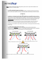
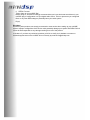
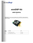
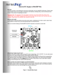
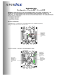
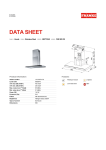
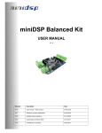
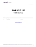
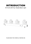
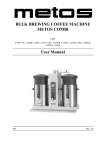
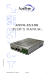
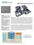
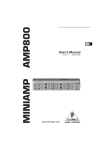
miniAMP
USER MANUAL
V1.2
Revision
Description
Date
V1.0
User manual – Initial version
25-02-2010
V1.1
Updated wiring section
Updated jumper configuration
05-05-2010
V1.2
Updated wiring and instructions for 2.1 mode
05-08-2010
Board Diagram
The following diagram shows the miniAMP board connectivity.
Configuration Headers
Power Input (12-24VDC)
I2S routing headers
PWM output for
additional ouput channel
Expansion connector J16
Expansion connector J2
Output jumpers:
2ch Bridge Tied Load (BTL) – Jumper closed
4ch Single Ended (SE) – Jumper open
Speaker outputs
See wiring configuration below
Expansion Connector J16
Pin
Description
Pin
Description
1
n/a
2
n/a
3
n/a
4
n/a
5
Ground
6
Ground
7
Ground
8
Ground
9
MCLKIN
10
I2S_DATA_IN1&2
11
I2S_DATA_IN3&4
12
I2S_DATA_IN5&6
13
I2S_DATA_IN7&8
14
I2S_IN_LRCLK
15
I2S_IN_BCLK
16
I2S_DATA_OUT1&2
17
I2S_DATA_OUT3&4
18
I2S_DATA_OUT5&6
19
IS2_DATA_OUT7&8
20
I2S_OUT_LRCLK
21
I2S_OUT_BCLK
22
3.3V
23
n/a
24
3.3V
25
GND
26
GND
27
n/a
28
n/a
miniAMP Basics
Before going any further, let’s summarize a couple of key points of the miniAMP:
- miniAMP is a Full Digital amplifier module taking its signal from an I2S bus. In other words, no
more potential ground loops. Your signal is digital all the way to the outputs of the amplifier.
- miniAMP can be configured in 2ch (2x20W @ 8Ω) or 4ch (2x20W @ 8Ω)
- miniAMP is a I2S slave device only which can automatically detect any type of incoming I2S
signal (up to 192kHz) making it the perfect fit for your custom audio board.
- miniAMP does not require any micro-controller programming and can operate in standalone
mode. All it needs is a simple jumper configuration to select its mode of operation.
I2S Expansion Bus 101
Configuration flexibility is a core design feature of the miniDSP concept. Using the I2S (Inter IC Sound)
protocol, synchronized digital audio data is shared between boards. Besides the advantages of better
noise immunity (vs analog audio), the choice of the widely known I2S protocol allows un-paralleled
design freedom. While flexibility typically comes at the detriment of ease of use, the hardware jumper
configuration of the miniAMP or miniDIGI boards allows a simple, yet reliable method to route the I2S
data lines as you wish.
I2S protocol consists of the following signals:
- Clocks: They provides synchronization between ICs
- I2S_IN: I2S input data lines carrying 2 x 24bit audio channels, in sync with the clocks
- I2S_OUT: I2S output data lines carrying 2 x 24bit audio channels, in sync with the clocks
miniAMP being an output device, only I2S_OUT lines are available for selection on the module.
Let’s move on to the typical audio flow diagram of a miniAMP module
Selection of
input I2S
channel
Digital signal
Analog signal
OUTPUTS
INPUTS
I2S
selection
header
I2S
channels
BTL /SE
Header
I2S
Amplifier
Control signals
(Mute/Power
down/Reset/Gain/
2 or 4ch output)
2x20W (BTL)
Or
4x10W (SE)
Or
2.1Ch
PWM SUB
channels
Step by Step configuration
Please pay attention to the following diagrams to clearly understand how to correctly configure
miniAMP:
1. STEP1: Configuring the miniAMP mode
miniAMP may be used in 3 possible configurations:
- 2 ch mode @20W each under 8ohms and in Bridge Tied Load (BTL) mode
- 4 ch mode @10W each under 4ohms and in Single Ended (SE) mode
- 2.1 mode with 2 ch @10W (SE/4ohm) and 1 ch @ 20W (BTL/8ohms)
This configuration is done from the configuration header with a simple jumper switch and by the
according output capacitor jumper. See below diagram for more info.
2. STEP2: Configuring the I2S routing
Read the plug-in datasheet to figure out which I2S channels output your loaded plug-in will use on
the miniDSP kit. This information is useful to understand how external I/O cards can link up to the
miniDSP kit. Taking for example the 2Way PEQ Crossover plug-in, you can read in the technical
specification section:
Digital Inputs
Digital Outputs
Plug-in IN#1&2 selectable on I2S_Data_In7&8
Plug-in OUT#1/2/3/4 available on I2S_Data_Out1/2/3/4
Un-processed signal from ADC on I2S_Data_Out5/6
Un-processed signal from Digital IN on I2S_Data_Out 7/8
In other words, if you want the miniAMP module to receive the plug-in output from the miniDSP kit
(processed audio, post filtering and crossover), you will need to select :
- either I2S_Data_Out1&2 or I2S_Data_Out3&4 in a 2ch mode configuration
- or both if a 4ch mode configuration.
Here is a zoomed up version of the I2S routing and configuration header for the miniAMP.
Configuration Header
Closed
Closed
-3dB
Closed
Open
3dB
Open
Closed
9dB
Open
Open
12dB
Config2
Config1
Closed
Open
Open
Open
Open
Closed
Mode
2ch
mode
4ch
mode
2.1
mode
Factory default configuration
2ch mode (BTL), Gain @ -3dB
Jumper symbol
4ch mode (SE)
Gain @ -3dB
2.1ch mode (BTL + SE)
Gain @ -3dB
Power Down
Mute
Gain1
Gain0
Config2
Config1
Reset
Gain
Power Down
Mute
Gain1
Gain0
Config2
Config1
Reset
Gain0
Power Down
Mute
Gain1
Gain0
Config2
Config1
Reset
Gain1
I2S Routing Headers for selection of which I2S
channel gets amplified
Jumpers always
closed for I2S clocks.
Do not remove
1
2
3
3
2
1 0
Outputs 1&2 Outputs 3&4
0
Output jumpers
2ch mode: All Closed
4ch mode: All Open
2.1ch mode: ch1&2 Open,
ch 3&4 closed
I2S_Data_OUT_ch1&2
I2S_Data_OUT_ch3&4
I2S_Data_OUT_ch5&6
I2S_Data_OUT_ch7&8
Jumper position
2ch: I2S_Data_OUT_ch1&2
4ch: I2S_Data_OUT_ch1&2
2.1ch: I2S_Data_OUT_ch3&4
I2S_Data_OUT_ch7&8
I2S_Data_OUT_ch5&6
I2S_Data_OUT_ch3&4
I2S_Data_OUT_ch1&2
Jumper position
4ch: I2S_Data_OUT_ch3&4
2.1ch: I2S_Data_OUT_ch1&2
Jumper symbol:
3. STEP3: Stacking miniAMP on top of a miniDSP/DIGI board
miniAMP is a I2S slave only device that requires clock & data from an I2S master device
(miniDSP/miniDIGI). When stacking miniAMP, here are the potential configurations:
- miniDSP (MCLK Slave) + miniDIGI (I2S Slave) + miniAMP (I2S Slave)
- miniDIGI (I2S Master) + miniAMP (I2S Slave)
- miniDSP (MCLK master) + miniAMP (I2S Slave)
Please refer to the respective manual of each product for information on master/slave configuration.
Boards share I2S and power by installing provided link cables on each side of the board.
Standoffs for board to
board connection.
Bottom board standoff is
secured with a bolt.
Link cables on each side
of the board allow sharing
of the expansion
connector signals( I2S &
power)
All output connectors on
the same side.
Note: To quickly confirm your jumper configuration, please use the Jumper Chart available in the
download section of miniDSP website.
4. STEP4: Providing DC power to the device
Before connecting your speakers to the miniAMP outputs, we strongly recommend to perform a
test run without your speakers connected. See below symbol of the polarity of the DC connector
miniAMP can operate from any DC power supply ranging from 12 to 24VDC. However, for best
performance, an 18-24VDC supply rated at 2.5A/ 60W is recommended. Even with its good Power
Supply Rejection Ratio (PSSR) specifications allowing it to reject noise from the supply, we would
still advise you to select a good quality DC supply. Finally, note that a single power supply to the
miniAMP module will provide power to all the other boards stacked in this configuration.
Important: Connect the DC jack before turning on the power supply to prevent any potential
damage. Turn On the power supply and make sure the blue LED on the module turns on.
If this step is un-successful for any reasons, please contact our tech support team before moving
further along.
5. STEP5: Wiring speaker cables to the module
With the amplifier turned OFF, connect your speakers to the module as shown below.
Depending on the miniAMP mode (2ch, 2.1, 4ch), speaker wiring and output jumper configuration
is different so please make sure to pay attention to the following diagrams
4 Channel Mode (SE)
2 Channel Mode (BTL)
+
CH1
-
+
-
+
-
CH1
CH2
+
CH2
-
+
-
+
-
CH3
Warning: All output jumpers removed in 4ch mode
Warning: All output jumpers in place in 2ch mode
2.1 Channel MODE (SE + BTL)
+
-
CH4
-
+
+
-
CH1
CH2
CH3
(SE)
(SE)
(BTL)
Warning: CH2 requires to be wired as shown on the diagram, otherwise the channels will be out of phase.
6. STEP6: First test
Time to listen to your miniDSP Rig!
Before doing so, we however strongly recommend that you insure levels are turned down in your
miniDSP plug-in configuration or at your digital audio source. This is to prevent any un-configured
filters or any other DSP settings to potentially harm your audio system.
Enjoy!
Disclaimer
As with any other products, we strongly recommend to exert caution when setting up your miniAMP
system. Improper configuration of the device could potentially damage your system and DSP4YOU Ltd
cannot be held responsible to any damage resulting from use of this product.
In doubts or if you have any technical questions you’d like to clarify, don’t hesitate to contact our
technical support team on the miniDSP forum or directly by email at [email protected]