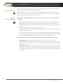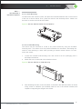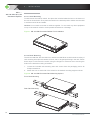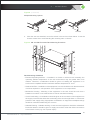
1
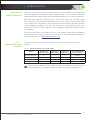
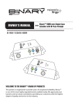
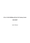
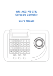
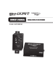
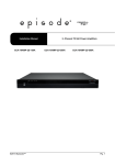
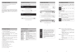
100 - S ER IES N ET WO R K SWI T C H ES
Install a t i on Ma n ua l
Unmanaged AV Rack Network Switches
C E R T I F I C AT I ONS AND WAR NI NGS
FCC Warning
This device has been tested and found to comply with limits for a Class A digital device,
pursuant to Part 15 of FCC Rules. These limits are designed to provide reasonable
protection against harmful interference when the equipment is operated in a commercial
environment. This equipment generates and radiates radio frequency energy and, if not
installed and used in accordance with the user’s manual, it may cause interference in which
case users will be required to correct interference at their own expenses.
CE Warning
This is a Class A product. In a domestic environment, this product may cause radio
interference in which case the user may be required to take adequate measures.
UL
Only the AN-100-SW-R-8, AN-100-SW-R-16, and AN-100-SW-R-24 port switches have
been evaluated by UL. The AN-100-SW-R-5 port switch has not been evaluated by UL.
About This Manual
This manual was created to provide a reference for installers and end users of Araknis
Networks products. It provides all known information regarding the installation, setup, use,
and maintenance of the product. This manual was created expressly for electronic use, but
has been formatted so that it may be printed and bound using either one-sided or front-andback printing.
The symbols below are used in this manual to identify certain information. Review the
definition of each symbol type to better understand notes later in the text.
Pro Tips
Pro tips are included in sections of the manual to add information that provides extra value,
utility, or ease-of-use for the installer or end user of the product. Pro tips may also link to
extra information that will provide a better understanding of application, technology or use
of the product or feature in question. These items are not required, but have been added
for your convenience.
Notes
Notes emphasize information important to the installation, setup, or use of the product
that are not essential to follow for safety of the equipment or user. Notes may be located
before or in the midst of the section they apply to, depending on the type of information.
These items are usually essential information, like the size or dimension of a separate part
required, or a critical step in the process, that, if missed, would cause the installer or end
user extra work to overcome.
Cautions
The caution symbol is used to indicate information vital to the safety of the equipment in use
with the product, or the product itself. Cautions are always provided before the information
they relate to. Not following a caution will almost always result in permanent damage to
equipment that is not covered by warranty.
Warnings
Warnings indicate information vital to the safety to the installer or end user of the product.
Warnings are always provided before the information they relate to. Not following a warning
may result in permanent damage to equipment and serious injury or death of the installer
or end user.
2
© 2013 Araknis Networks®
TABLE OF CONTENTS
Certifications and
Warnings
Table of Contents
Figures and Tables
1. Introduction
2. Installation
3. Connecting Network
Devices
4. Product Layout
5. Specifications
6. Appendix
FCC Warning
CE Warning
UL
About This Manual
Pro Tips
Notes
Cautions
Warnings
Welcome to Araknis® Networks
1.1Araknis® 100-Series Overview
1.2Features
1.3 Package Contents
1.4 Recommended for Installation
2.1 Basic Instructions
2.2 Switch Placement
2.2.1 General Guidelines
2.2.2 AN-100-SW-R-5 Placement Options
2.2.2.1 Shelf Mounting
2.2.2.2 On-Wall Mounting
2.2.3 AN-100-SW-R-8/16/24 Placement Options
2.2.3.1 Shelf Mounting
2.2.3.2 Rack Mounting
2.2.3.3 On-Wall Mounting
2.3.Powering the AN-100-SW-R Switch
2.3.1 AC Electrical Requirements
2.3.2 AN-100-SW-R-5
2.3.2.1 Power Plug Connection
2.3.3. AN-100-SW-R-8/16/24
2.3.3.1 Power Plug Connection
3.1 Wiring Recommendations
3.2 Application Diagram
3.3 Connection Instructions
4.1 Front Panel Layout
4.2 Side Layout
4.3 Rear Panel Layout
6.1Troubleshooting
6.1.1 No Connectivity
6.1.2 Power Issues
6.2Warranty
6.3 Contacting Technical Support
2
2
2
2
2
2
2
2
2
3
4
5
5
5
6
7
7
8
8
10
10
11
11
11
12
12
12
14
15
15
15
15
15
15
16
16
16
16
17
17
18
18
19
20
20
20
20
21
21
3
www.araknisnetworks.com | Support: 866.838.5052
FIGURES AND TABLES
Figures
Figure 1. AN-100-SW-R-5 Package Contents
Figure 2. AN-100-SW-R-8/16/24 Package Contents
Figure 3. Single Switch Network
Figure 4. Multiple Switches in Network
Figure 5. AN-100-SW-R-5 Rubber Foot Installation
Figure 6. AN-100-SW-R-5 On-Wall Mounting
Figure 7. AN-100-SW-R-8/16/24 Rubber Foot Installation
Figure 8. AN-100-SW-R-8/16/24 Rack Mounting Options
Figure 9. AN-100-SW-R-8/16/24 Rack Mounting Procedure
Figure 10. AN-100-SW-R-8/16/24 Wall Mounting Option
Figure 11. AN-100-SW-R-5 Power Plug Connection
Figure 12. AN-100-SW-R-8/16/24 Power Plug Connection
Figure 13. Application Diagram
Figure 14. Front Panel Layout
Figure 15. Side Layout
Figure 16. Rear Panel Layout
7
7
9
9
11
11
12
12
13
14
15
15
16
17
18
19
Table 1. Araknis Networks 100-series Family
Table 2. AC Electrical Requirements
Table 3. Cable and Connector Recommandations
Table 4. 1 Gbps LED Indicator
Table 5. Link/Act LED Indicator
Table 6. Power LED Indicator
Table 7. Specifications
5
15
16
17
17
17
19
Tables
4
© 2013 Araknis Networks®
1 . I N T R O D U C TI ON
Welcome to
Araknis® Networks
Thank you for choosing an Araknis AN-100-SW-R-5, AN-100-SW-R-8, AN-100-SW-R-16,
or AN-100-SW-R-24 Unmanaged AV Rack Network Switch. The 100-series unmanaged
network switch is an enterprise-class switch specifically designed for use in AV Rack applications.
With front-facing indicators, rear-facing ports, and fan-less design, the 100-series switch
was designed for easy installation and high performance in an environment where traffic
on the network and the number of users could increase continuously. The switch provides
10/100/1000Mbps capability on all ports and operates as a plug-and-play device, autodetecting connections to other switches to allow straight-through patch cables throughout
an installation.
This manual will guide you through the layout of the device, explain proper installation,
and describe how to deploy the switch in your network to achieve the best performance.
For more information, visit www.araknisnetworks.com.
1.1 —
Araknis 100-Series
Overview
®
The following table lists the models available in the 100-series family of network
switches.
Table 1. Araknis Networks 100-series Family
Model
AN-100-SW-R-5
AN-100-SW-R-8
AN-100-SW-R-16
AN-100-SW-R-24
Number of
Ethernet Ports
Number of
PoE Ports
Number of
SFP Ports
Internal/External
Power Supply
8
0
0
Internal
5
16
24
0
0
0
0
0
0
External
Internal
Internal
Only the AN-100-SW-R-8, AN-100-SW-R-16, and AN-100-SW-R-24 port switches have
been evaluated by UL. The AN-100-SW-R-5 switch has not been evaluated by UL.
5
www.araknisnetworks.com | Support: 866.838.5052
1 | INTRODUCTION
1.2 —
Features
Gigabit Ethernet with Auto MDI/MDI-X Detection
All ports provide 10/100/1000Mbps line rate speed with auto-negotiation and auto
Medium Dependent Interface (MDI)/Medium Dependent Interface Crossover (MDI-X)
detection. Auto-negotiation speed automatically selects the best connection speed (10,
100, or 1000Mbps) and duplex mode (half or full duplex) for communication with attached
devices. Auto MDI/MDI-X crossover detection automatically adjusts for the Ethernet
cable type in use (straight-through or crossover). This makes connecting the device to
other network devices, such as other switches or routers, very simple and easy.
Jumbo Frame Support
100-series Unmanaged Switches support frames up to 9.6 Kilobytes, called Jumbo
Frames. This feature improves network throughput and reduces overall CPU utilization
during large file transfers, such as video streams, by allowing a bigger packet of data to
be passed in each Ethernet frame.
Non-Blocking Architecture with Full Wire Speed Forwarding
Ethernet frames run from the input port to the output port through the “backplane” of the
switch. The AN-100-SW-R network switch backplane is capable of handling all traffic
on all ports at the same time. Having this non-blocking switch fabric architecture means
the backplane is so fast that there is no significant delay for data rate due to backplane
congestion. Thanks to this, the switch features Full Wire Speed Forwarding, meaning
that the nominal traffic speed at all Ethernet ports can be up to 1 Gbps simultaneously.
Multiple Mounting Options
In addition to industry-standard options for shelf- and rack-mounting, Araknis network
switches are also capable of over a dozen possible custom rack positions, and even
wall-mounting options, using only the accessories included in the box.
Fan-less Design
The device is designed so that heat from the CPU is dissipated through efficient heat
sinks. No fans are necessary to maintain a safe temperature, resulting in ultra-silent
operation.
Quality of Service (QoS) Support
The 100-series unmanaged switches support Quality of Service (QoS). The switch is
aware of priority levels of traffic received and forwards it based on that priority level.
Incoming traffic is always examined for QoS priority encoding.
6
© 2013 Araknis Networks®
1 | INTRODUCTION
1.3 —
Package Contents
Figure 1. AN-100-SW-R-5 Package Contents
Screws (4)
AN-100-SW-5 Gigabit Ethernet Switch (1)
Quick Installation Guide (1)
Rack Mount Kit (1)
Rubber Feet (1)
Wall Anchors (4)
DC Power Supply (1)
Figure 2. AN-100-SW-R-8/16/24 Package Contents
AN-100-SW-R Gigabit Ethernet Switch (1)
Quick Installation Guide (1)
1.4 —
Recommended for
Installation
Rubber Feet (1)
Rack Mount Kit (1)
AC Power Cord (1)
• #2 Phillips screwdriver
• Screws and Anchors - for wall-mount installation if applicable (use a fastener rated and
specified for use in the wall material that can safely hold the weight of the model in use)
• Rack screws- for rack installation
• Drill and Drill Bit- for installation of wall-mount screws or anchors
7
www.araknisnetworks.com | Support: 866.838.5052
2 . I N STA L L ATI ON
2.1 —
Basic Instructions
These are the basic steps required to install the AN-100-SW-R network switch. During the
installation, refer to the listed sections for more detailed information as needed.
Do not power the AN-100-SW-R until it is indicated to do so in the instructions.
(See Section 2.3, page 15 for power requirements.)
1.Unpack and set or mount the switch in the desired location. See section 2.2 (page 9)
for more information.
2.
Make connections to the equipment requiring Ethernet access. Connect Ethernet
cables between the ports on the switch and the LAN ports on the equipment. Leave
one port open on the switch for connection to the router or switch providing Internet
access. See Section 3.3 (page 16) for wiring best practices and device connection.
3.Connect an Ethernet cable between the port of the switch or router providing network
access and any open Ethernet port on the AN-100-SW-R. The switch will automatically
detect the connection and configure it correctly, so no crossover cable is required.
4.Power on the AN-100-SW-R network switch and any connected equipment. Confirm
that each port is operating correctly by checking the Link/Act LED for the port. A solid-lit
LED indicates that a connection is working correctly. A blinking LED indicates the port
is passing traffic. If a device is not connecting properly, consult the Troubleshooting
section, on page 20.
5.
Test the network connectivity of each connected device. If all devices are properly
communicating on the network, installation is now complete.
Pro Tip: Having a record of the location, wire length, and connection path for each network
device can save a lot of time and expense later. Take some time to record a summary of the
network architecture before calling the job “done.”
8
© 2013 Araknis Networks®
2 | INSTALLATION
Figure 3. Single Switch Network
Example - 1
Desktop
PC
Server
Printer/
Scanner
AppleTV
IP
Phone
Figure 4. Multiple Switches in Network
Example - 2
Desktop
PC
Server
Printer/
Scanner
AppleTV
IP
Phone
IP Camera
IP Surveillance
NVR
9
www.araknisnetworks.com | Support: 866.838.5052
2 | INSTALLATION
2.2 —
Switch Placement
This section describes proper placement and mounting for the AN-100-SW-R network
switch, including shelf, rack, and on-wall installation.
Note: Section 2.2.1 applies to all AN-100-SW-R models. Section 2.2.2 addresses all
placement options for the AN-100-SW-R-5 port switch. Section 2.2.3 covers all placement
options for the AN-100-SW-R 8/ -16,/ -24 models.
2.2.1 —
General Guidelines
Consider the following guidelines before choosing any location or mounting type for
the switch:
•Make sure that the switch is accessible and that the cables can be connected with ease.
Using cable management accessories is highly recommended for rack installations.
•Keep cabling away from sources of electrical noise, power lines, and fluorescent lighting
fixtures.
•Keep the switch away from water and moisture sources.
•Power the device from an outlet with adequate capacity. Plugging in the switch must not
overload the circuit in use.
•The use of a power conditioner or surge protector is highly recommended for all attached
network equipment. A surge at one piece of unprotected equipment could pass through
the network cable and damage other devices, even if they are protected.
Do not deploy the device in a location where any of the following conditions exist:
•
High Temperature: The ambient temperature must not exceed 104°F (40°C).
•Low Air Flow: Both side panels must be unobstructed to prevent overheating. Leave
3 inches of open air space on all sides of the network switch. Avoid covering any
ventilation holes.
•Mechanical Instability: The device should be level, stable, and secure to avoid it sliding
or shifting out of position. The included rubber feet will help prevent unwanted movement
for shelf-mounted switches. Do not mount the switch to any rack or wall that is unstable
or damaged.
10
© 2013 Araknis Networks®
2 | INSTALLATION
2.2.2 —
AN-100-SW-R-5
Placement Options
2.2.2.1 Shelf Mounting
To shelf-mount the network switch, first place the included adhesive feet on the bottom
of the unit as shown below. Then, place the switch in the desired position. Make sure
the shelf or surface used is flat and stable.
Figure 5. AN-100-SW-R-5 Rubber Foot Installation
2.2.2.2 On-Wall Mounting
The switch may be mounted on a wall or any other surface by using the included
mounting ears. This allows for a low-profile installation for the switch, eliminating the
need for extra shelving or racks when providing a network switch solution. To wallmount the switch:
1.
Locate the included wall-mounting ears and screws from the packaging and a
#2 Philips screwdriver.
2. Attach the ears to each side of the switch as shown:
Figure 6. AN-100-SW-R-5 On-Wall Mounting
3.After attaching the ears, mount the switch on the wall in the desired location as shown
using screws or fasteners (not included) rated for use in the surface material, and
capable of supporting the weight of the switch.
11
www.araknisnetworks.com | Support: 866.838.5052
2 | INSTALLATION
2.2.3 —
AN-100-SW-R-8/16/24
Placement Options
2.2.3.1 Shelf Mounting
To shelf-mount the network switch, first place the included adhesive feet on the bottom of
the unit as shown below. Then place the switch in the desired position. Make sure the shelf
or surface used is flat and stable.
Caution: Do not stack more than 4 switches together. Do not stack any other equipment
on top of the network switch to avoid possible interference or damage.
Figure 7. AN-100-SW-R-8/16/24 Rubber Foot Installation
AN
2
1
4
3
6
5
8
7
10
9
12
11
14
0-S
W- R-1
6
16
ct
k/A
Lin
13
-10
15
ps
1 Gb
2.2.3.2 Rack Mounting
The AN-100-SW-R-8, AN-100-SW-R-16, and AN-100-SW-R-24 models include a variety of
rack mounting hole options that allow for front, rear, or angled positioning in the rack. Follow
these steps to rack-mount the switch, using the images for reference when choosing the
holes for the desired mounting orientation:
1.Locate the included rack-mounting ears and screws from the packaging and a #2
Philips screwdriver.
2. Attach the ears to each side of the switch for the desired mounting angle as shown:
Figure 8. AN-100-SW-R-8/16/24 Rack Mounting Options
Front Rack Mounting
1 Gbp
s
1
2
Rear Rack Mounting
3
4
5
6
7
8
9
10
11
13
15
Link
12
/Act
14
16
AN-
100
-SW
-R-1
6
1 Gbp
s
1
2
3
4
5
6
7
8
9
10
11
13
15
Link
12
/Act
14
16
AN-
100
-SW
-R-1
6
12
© 2013 Araknis Networks®
2 | INSTALLATION
Figure 8. (continued)
Multiple Mounting Options
Standard
Protruding
Recessed
3.After the ears are attached, mount the switch in the rack as shown below. Insert the
bottom screws first to avoid bending the mounting ears or chassis.
Figure 9. AN-100-SW-R-8/16/24 Rack Mounting Procedure
1 Gb
ps
1
2
3
4
5
6
7
8
9
10
11
12
13
15
Li n
14
k / Ac
t
16
AN
-10
0-S
W-R
-16
Rack Mounting Guidelines
• Elevated Operating Ambient - If installed in a closed or multi-unit rack assembly, the
operating ambient temperature of the rack environment may be greater than room
ambient. Therefore, consideration should be given to installing the equipment in an
environment compatible with the maximum ambient temperature of 104 F.
•Reduced Air Flow - Installation of the equipment in a rack should be such that the amount
of air flow required for safe operation of the equipment is not compromised.
•Mechanical Loading - Mounting of the equipment in the rack should be such that a
hazardous condition is not achieved due to uneven mechanical loading.
•Circuit Overloading - Consideration should be given to the connection of the equipment to
the supply circuit and the effect that overloading of the circuits might have on overcurrent
protection and supply wiring. Appropriate consideration of equipment nameplate ratings
should be used when addressing this concern.
•Reliable Earthing - Reliable earthing of rack-mounted equipment should be maintained.
Particular attention should be given to supply connections other than direct connections
to the branch circuit (e.g. use of power strips).”
13
www.araknisnetworks.com | Support: 866.838.5052
2 | INSTALLATION
2.2.3.3 On-Wall Mounting
The AN-100-SW-R is designed to be mounted on-wall if desired by using the same parts
meant for rack-mounting. This allows for a low-profile installation for the switch, eliminating
the need for extra shelving or racks when providing a network switch solution. To wallmount the switch:
4.Locate the included wall-mounting ears and screws from the packaging and a #2
Philips screwdriver.
5. Attach the ears to each side of the switch as shown:
Figure 10. AN-100-SW-R-8/16/24 Wall Mounting Option
OFF50
-60H
z
ON10
0-240V
AC
16
14
12
10
15
13
8
11
6
9
4
2
7
5
3
1
6.After attaching the ears, mount the switch on the wall in the desired location as shown
using drywall screws or fasteners suitable for the wall surface material (not included).
For wall mounting, we recommend using 4 drywall screws, minimum of 1-1/4” X 8 GA with
anchors
14
© 2013 Araknis Networks®
2 | INSTALLATION
2.3 —
Powering the
AN-100-SW-R Switch
2.3.1 —
AC Electrical
Requirements
2.3.2 —
AN-100-SW-R-5
Table 2. AC Electrical Requirements
Input Voltage (AC Only)
100-240V AC, 50~60Hz
The AN-100-SW-R-5 is designed with an external DC power supply that connects inline
between the power outlet and the DC input on the switch.
2.3.2.1 Power Plug Connection
Figure 11. AN-100-SW-R-5 Power Plug Connection
2.3.3 —
AN-100-SW-R-8/16/24
The AN-100-SW-R-8, -16, and -24 are designed with an internal power supply, and
require the use of the included or an equivalent grounded IEC cable to connect the
switch to an outlet.
2.3.3.1 Power Plug Connection
Figure 12. AN-100-SW-R-8/16/24 Power Plug Connection
9
11
13
15
ON 100-240VAC
10
12
14
16
OFF 50-60Hz
Pro Tip: The use of a power conditioner or surge protector is highly recommended
for all connected network equipment. A surge at one piece of unprotected equipment
could pass through the network cable and damage other devices, even if they are
protected. Power conditioners with additional Ethernet protection are available at
http://www.snapav.com/c-8-power-products.aspx.
Note: AN-100-SW-R-8 does NOT have a power switch.
15
www.araknisnetworks.com | Support: 866.838.5052
3 . C O NNE C TI NG NETWOR K DEV I CES
Setup of the AN-100-SW-R is very simple and requires nothing more than connections
to other equipment and power. This switch provides automatic crossover detection
functionality for any port, so connections can be made to other switches without the need
for a crossover cable between devices.
3.1 —
Wiring
Recommendations
Make all Ethernet connections using twisted-pair, 568B-terminated straight-through cables
manufactured and terminated to meet the Cat5e/6/+ standard in use for the installation.
Patch cables may be stranded. Bulk wire should be solid core to permit the longest run
possible. No cable length should be over 100 meters in total, containing a maximum of 10
meters of stranded patch cables. It is highly recommended to test every cable in use with
a network analyzer prior to finalizing the installation.
Table 3. Cable and Connector Recommendations
Item
Description
Solid Core, EIA/TIA certified
Cat5e or better
Bulk Wire
Connectors for Wire
RJ45 of the same standard
as the bulk cable in use
Patch Cables
Stranded, EIA/TIA certified
Max Length (If applicable)
100 meters without patch cables;
90 meters with patch cables
--------No more than 10 meters of patch
cables to a run in total
Pro Tip: For guaranteed, hassle-free performance, use Binary™ bulk wire, and Wirepath™
cable connectors and manufactured patch cables. All of the items are available at
http://www.snapav.com/c-13-bulk-wire.aspx.
3.2. —
Application Diagram
Figure 13. Application Diagram
Internet
(Modem)
Router
Araknis Switch
IP Camera
(external power
supply needed)
AppleTV
Desktop
PC
Printer/
Scanner
IP Phone
(external power
supply needed)
IP Surveillance
NVR
Leave all equipment un-powered while making connections.
3.3 —
Connection
Instructions
1.Install the network switch and any equipment to be connected.
2. Route bulk wire or patch cables between equipment locations.
3. Terminate and test all cables.
4.Connect each cable between the LAN port on the equipment requiring network access
and a port on the switch. Leave one switch port open to allow connection to the rest of
the network.
5. Connect a network cable from the switch to the device providing network connectivity.
6. Power up all equipment and test each attached device for network connectivity.
16
© 2013 Araknis Networks®
4 . PR O D U C T LAYOUT
This section describes the hardware layout of the 100-series unmanaged network switch.
Each connection, indicator, and control is summarized.
4.1 —
Front Panel Layout
Figure 14. Front Panel Layout
2
1
1 Gbps
7
9
11
13
15
8
10
12
14
16
Link/Act
1
3
5
7
9
11
13
15
2
4
6
8
10
12
14
16
Link/Act
AN-100-SW-R-16
3
1. Table 4. 1 Gbps LED Indicator
Behavior
Off
On
Description
No device connected/Connected device
supports 10/100Mbps only
Device connected at 1Gbps speed
2. Table 5. Link/Act LED Indicator
Behavior
Off
Blinking
Description
No device connected
Device is connected and traffic running
3. Table 6. Power LED Indicator
Behavior
Description
Off
Power off.
On
Power on.
17
www.araknisnetworks.com | Support: 866.838.5052
4 | PRODUCT LAYOUT
4.2 —
Side Layout
Figure 15. Side Layout
1
2
1. Ventilation Slots
Allows airflow through the chassis to keep the device cool.
2.Rack Mounting Holes
The combination of threaded holes at the front and rear of each side allow for many
variations in mounting options.
4.3 —
Rear Panel Layout
Figure 16. Rear Panel Layout
1
2
3
1
3
5
7
9
11
13
15
ON 100-240VAC
2
4
6
8
10
12
14
16
OFF 50-60Hz
1. Ethernet Ports (RJ45)
Connect Ethernet network cables routed to equipment.
2.Master Power Switch
Toggle Switch for master power control.
3. Power Jack
Attach an IEC power cable.
Note: AN-100-SW-R-8 does NOT have a power switch.
18
© 2013 Araknis Networks®
5 . S PE C I F I C ATI ONS
Table 7. Specifications
Model
AN-100-SW-R-5
AN-100-SW-R-8
AN-100-SW-R-16
AN-100-SW-R-24
Interface
Ports
10/100/1000Base
RJ-45 Ports
5
8
16
24
1000Base SFP
---
---
---
---
---
---
---
---
PoE ports
(In PoE Models)
Physical Configuration
Flash Memory
---
---
2MB
2MB
SDRAM
---
---
64KB (SRAM)
64KB (SRAM)
Packet Buffer
128KB
512KB
Performance
MAC Address Table
4K
8K
Switching Capacity
10Gpbs
16Gpbs
32Gpbs
48Gpbs
Forwarding Rate
7.4Mpps
11.9Mpps
23.8Mpps
35.7Mpps
12.9 x 1.7 x 8.2
12.9 x 1.7 x 8.2
Jumbo Frame Support
9K
Environmental
Dimensions (Inches)
(W x H x D)
Power Supply
Maximum Power
Consumption (W)
5.1 x 0.9 x 3.0
8.9 x 1.7 x 4.8
5V DC, 2.5A
Adapter
2.5W
100-240V AC, 50/60 Hz
3.5W
Operating Temperature (F)
11W
4.0
4.4
32 to 104° F
Humidity
(non-condensing)
Weight (lbs.)
8W
10 to 90%
0.6
2.0
19
www.araknisnetworks.com | Support: 866.838.5052
6 . APPE ND I X
6.1 —
Troubleshooting
Use the sections below to troubleshoot issues with the switch. If the problem persists,
contact Araknis Networks® Customer Service at (866) 838-5052.
6.1.1 —
No Connectivity
If one or more attached devices suffer from low or no network connectivity after installation,
follow these steps to identify the issue:
1.Reset the switch and router, and then the device(s) with issues. If the problem persists,
continue to step 2.
2. Are there one or multiple devices with issues?
A. If one device is having an issue:
ii.Change the network connection type to DHCP and reset the connection. If
an IP address is assigned to the device, then it should be working properly. If
nothing changes, the cabling must be changed or repaired.
iii.Using a tested patch cable that is known to work correctly, swap out the cable
from the switch to the network device and test again.
B. If multiple devices are having an issue:
6.1.2 —
Power Issues
i.Change the port the device is connected to on the switch. If the issue remains,
there is a problem with the cabling or the attached device’s network settings.
i.Check the Power LED indicator on the switch to make sure it is receiving
power. If it is not illuminated solid, see the next troubleshooting section, Power
Issues, to determine source of the issue.
ii.Check the connection from the switch to its host device. The switch may have
lost network access from the device feeding it. If the device feeding signal is
okay then the cable may be damaged.
iii.Using a tested patch cable that is known to work correctly, swap out the cable
from the switch to the network connection and test again.
If the switch is not working correctly, and the power LED is not illuminated solid or is not
illuminated at all, then try these steps to identify the issue:
1.Power cycle the switch. If the LED does not illuminate and remain solid, continue to the
next step. Otherwise, test devices for connectivity and confirm the system is operating
correctly. Make sure that ventilation is adequate. Overheating can cause the unit to
shut down for self-protection.
2.Change out the power cord or supply with another of the same type, and test again.
The power supply or cable may be damaged or defective.
20
© 2013 Araknis Networks®
6 | APPENDIX
6.2. —
Warranty
2
year
2 Year Limited Warranty
Araknis Networks® products have a 2-Year Limited Warranty. This warranty includes parts
and labor repairs on all components found to be defective in material or workmanship
under normal conditions of use. This warranty shall not apply to products which have been
abused, modified or disassembled. Products to be repaired under this warranty must be
returned to SnapAV or a designated service center with prior notification and an assigned
return authorization number (RA).
6.3. —
Contacting
Technical Support
Phone: (866) 838-5052
Email:[email protected]
21
www.araknisnetworks.com | Support: 866.838.5052
© 2013 Araknis Networks®
131028-1738