1
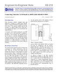
CrossSync User Manual For LeCroy Protocol Analyzers CrossSync Control Panel Version 2.21 Document Version 1.12 August 2011 LeCroy Protocol Solutions Group Copyright © 2011 LeCroy Protocol Solutions Group. All rights reserved. Trademarks and Servicemarks: LeCroy, LeCroy Protocol Solutions Group, CATC, SASSuite, SATASuite, SASTracer, SATracer, SASTrainer, SATrainer, SASTracker are trademarks of LeCroy. Microsoft, Windows, Windows 2000, and Windows XP are registered trademarks of Microsoft Inc. Intel and Pentium are registered trademarks of Intel Corporation. All other trademarks and registered trademarks are property of their respective owners. THE SPECIFICATIONS AND INFORMATION REGARDING THE PRODUCTS IN THIS MANUAL ARE SUBJECT TO CHANGE WITHOUT NOTICE. ALL INFORMATION, EXAMPLES AND RECOMMENDATIONS IN THIS MANUAL ARE BELIEVED TO BE ACCURATE BUT ARE REPRESENTED WITHOUT WARRANTY OF ANY KIND, EXPRESS OR IMPLIED. USERS ARE FULLY RESPONSIBLE FOR THEIR APPLICATION OF ANY PRODUCTS. THE SOFTWARE LICENSE AND LIMITED WARRANTY FOR THE ACCOMPANYING PRODUCT ARE SET FORTH IN INFORMATION THAT SHIPPED WITH THE PRODUCT AND ARE INCORPORATED HEREIN BY THIS REFERENCE. IF YOU ARE UNABLE TO LOCATE THE SOFTWARE LICENSE OR LIMITED WARRANTY, CONTACT LeCroy FOR A COPY. Copyright © 2011, LeCroy Corporation; All rights reserved. This document may be printed and reproduced without additional permission, but all copies should contain this copyright notice. LeCroy Corporation 3385 Scott Blvd. Santa Clara, CA 95054 TEL: 800-909-7112 (USA and Canada) TEL: 408-653-1260 (worldwide) CrossSync User Manual ii Contents Chapter 1: Introduction...........................................................................................1 CrossSync Multi-Protocol Analysis option ................................................................................ 1 CrossSync-Capable Products ..................................................................................................... 2 Overview of the CrossSync Hardware........................................................................................ 2 Overview of the CrossSync Software ......................................................................................... 2 Chapter 2: Hardware Setup ....................................................................................3 CrossSync Hardware Requirements........................................................................................... 3 Host PC Connections Using Various Configurations ............................................................... 6 CrossSync Cabling for Various Configurations ...........................................................................................6 Connecting a Sierra M6-1 SAS/SATA Analyzer and a Advisor T3 USB Analyzer via the Micro-D Sync Cable ..................................................................................................................6 Connecting Two Voyager M3i USB Analyzers via the CATC Sync Expansion Card (ACC-EXP-002-X) ...................................................................................................................................7 Connecting an Advisor T3 and a Sierra M6-2 .....................................................................................8 Connecting an Advisor T3, a Voyager M3i and a Summit T3-16 ......................................................9 Connecting a SierraFC M8-4 and a Summit T3-16 via the CATC Sync Expansion Card (ACC-EXP-002-X) .................................................................................................................................10 Connecting Three Analyzers with Built-in Micro-D Sync Ports ................................................................11 Connecting Three Analyzers with DB-9 Sync Ports...................................................................................12 Connecting Kibra 380 DDR3 Protocol Analyzer for CrossSync with the IOTA Software Suite..............13 Chapter 3: Software ..............................................................................................15 CrossSync Software Overview.................................................................................................. 15 CrossSync Control Panel........................................................................................................... 16 Launching the Application ...........................................................................................................................16 Applications Tab .................................................................................................................................16 Application Overview ....................................................................................................................................17 Run Sequence Tab ..............................................................................................................................17 CrossSync User Manual iii LeCroy Corporation Contents Trace File Tab ......................................................................................................................................18 Time Tune Tab .....................................................................................................................................19 General Tab .........................................................................................................................................19 Dockable Bar .......................................................................................................................................20 System Tray .........................................................................................................................................20 Main Buttons .......................................................................................................................................21 Session Configuration ..................................................................................................................................23 Topology View .....................................................................................................................................24 CrossSync Synchronized Time Stamps ................................................................................... 25 Appendix A: How to Contact LeCroy ..................................................................27 Index:.................................................................................................................... 29 iv CrossSync User Manual Chapter 1 Introduction The LeCroy CrossSync control panel provides synchronization for complete end‐to‐end visibility into multi‐protocol systems. This document discusses the overview, hardware setup and software for the CrossSync Multi‐Protocol analysis system. CrossSync Multi-Protocol Analysis option CrossSync is LeCroy’s analyzer synchronization solution that enables time‐aligned display of protocol traffic from multiple daisy‐chained analyzers showing packet traffic from multiple high‐speed serial busses. A lightweight software control panel allows users to select analyzers for synchronization and manage the recording process. Captured traffic is displayed using the latest analyzer software (in separate windows) with all the protocol specific search and reporting features. Captured packets are displayed in separate windows that share a common time scale. Navigating the traffic in either direction will scroll to the same timestamp in a synchronized window. When using the CrossSync option, users can access the full complement of analysis capabilities available within the individual LeCroy software. Search, reporting, and decoding all operate normally. The CrossSync option supports a wide combination of LeCroy's flagship analyzers including PCI Express Gen 1, Gen 2, and Gen 3; USB 2.0 and 3.0; Serial ATA (SATA) 1.5, 3, and 6Gbps; Serial Attached SCSI (SAS) 3 and 6Gbps; Fibre Channel 1, 2, 4, and 8 Gbps systems and DDR3. CrossSync User Manual 1 LeCroy Corporation CrossSync‐Capable Products CrossSync-Capable Products The following products support CrossSync operation: TABLE 1.1: LeCroy Protocol Suites and Products Required Software USB Protocol Suite 4.20 and later SAS/SATA Protocol Suite 4.00 and later FC Protocol Suite 3.25 and later PETracer 6.50 and later DDR Protocol Suite 1.01 IOTA Software Suite 1.00 Product USB Voyager M3i USB Advisor T3 SAS/SATA Sierra M6‐4 SAS/SATA Sierra M6‐2 SAS/SATA Sierra M6‐1 SierraFC M8‐4 PCIe Summit T28 PCIe Summit T3‐16 PCIe Summit T3‐8 Kibra 380 DDR3 N/A LeCroy will add support for more protocol analysis products in the future. Overview of the CrossSync Hardware The CrossSync capability requires that analyzers are connected using their Sync ports. CrossSync can be used with the built‐in Sync port included on every Advisor T3 and Sierra M6‐1 analyzer. For owners of LeCroy’s Sierra, Summit T3, and Voyager M3i based analyzers, the CATC Sync port requires the optional expansion board (ACC‐EXP‐002‐X). There may be additional configurations added in the future for platforms that can support the CATC Sync framework. Overview of the CrossSync Software The CrossSync control panel requires updated analyzer software that supports the new CrossSync framework. The CrossSync control panel does not have a separate installer, instead it is embedded in the Protocol Suite installers. The solution includes a lightweight software control panel that starts and stops recording across daisy‐chained analyzers. Users can sync or un‐sync traces on‐the‐fly. The Time Tune feature provides an interactive slider for adjusting the off‐set between displays. This makes it easy to see latency across busses. Note: If the system prompts you that it cannot write a trace file to disk: 1. Make sure that the trace‐file destination folder has write/create permissions. (For example, the target directory might be the network file system, which typically does not have write/create permissions.) 2. Make sure that the Windows (or other) Firewall Settings for all LeCroy applications are set to Public. 2 CrossSync User Manual Chapter 2 Hardware Setup CrossSync Hardware Requirements The CrossSync capability requires that analyzers are connected using their Sync ports. CrossSync can be used with the built‐in Sync port included on every Advisor T3 and Sierra M6‐1 analyzer. For owners of LeCroy’s Sierra, Summit T3, and Voyager M3i based analyzers, the CATC Sync port requires the optional expansion board (ACC‐EXP‐002‐X). Up to eight analyzers may be connected in a single chain. The AdvisorT3 and Sierra M6‐1 use the built‐in Micro‐D Sync port and only require the Micro‐D Sync cable (AC031XXA‐X). Systems with an expansion slot (such as Sierra M6‐4, Sierra M6‐2, SierraFC M8‐4, Voyager M3i, and Summit T3‐16) require the CATC Sync Expansion Card and DB‐9 Sync cable (ACC‐ EXP‐002‐X). The Kibra 380 DDR3 and PCIe Summit T28 use built‐in DB‐9 sync ports and require a DB‐9 sync cable (ACC‐EXP‐002‐X). Analyzers daisy‐chained via sync cables will automatically synchronize time stamps, trigger, recording start, and recording stop. CrossSync User Manual 3 LeCroy Corporation CrossSync Hardware Requirements TABLE 2.2: LeCroy Analyzers and Cables Required for CrossSync Option Analyzers and Cables Product Analyzers with built‐in Micro‐D Sync Ports requiring Micro‐D Sync cable (AC031XXA‐X) USB Advisor T3 Analyzers requiring CATC Sync Expansion Cards and DB‐9 Sync cable (ACC‐EXP‐002‐X) SierraFC M8‐4 SAS/SATA Sierra M6‐1 SAS/SATA Sierra M6‐4 SAS/SATA Sierra M6‐2 PCIe Summit T3‐16 PCIe Summit T3‐8 USB Voyager M3i Analyzers with built‐in DB‐9 Sync ports requiring DB‐9 sync cable (ACC‐EXP‐002‐X) Kibra 380 DDR3 PCIe Summit T28 Required Cables DB‐9 Sync cable (ACC‐EXP‐002‐X) 4 CrossSync User Manual CrossSync Hardware Requirements LeCroy Corporation TABLE 2.2: LeCroy Analyzers and Cables Required for CrossSync Option Analyzers and Cables Product Micro‐D Sync cable (AC031XXA‐X) Micro‐D to DB‐9 Sync cable (AC030XXA‐X) CrossSync User Manual 5 LeCroy Corporation Host PC Connections Using Various Configurations Host PC Connections Using Various Configurations An analyzer connected in a CrossSync configuration may be connected to the Host PC using any host interface connection supported by the analyzer. The CrossSync control panel running on the Host PC can then be used to control all synchronized analyzers for time‐synchronized recording sessions. CrossSync Cabling for Various Configurations Connecting a Sierra M6-1 SAS/SATA Analyzer and a Advisor T3 USB Analyzer via the Micro-D Sync Cable The devices are connected using their built‐in Sync ports. Perform the following steps: 1. Make sure to stop any recordings in progress. Note: You may plug/unplug the sync cable while the analyzer unit is powered on. 2. Connect the Advisor T3 to the Sierra M6‐1 using the built‐in Sync ports via the Micro‐D Sync cable. Figure 2.1: Daisy-chained Sierra M6-1 and Advisor T3 Analyzers 6 CrossSync User Manual Host PC Connections Using Various Configurations LeCroy Corporation Connecting Two Voyager M3i USB Analyzers via the CATC Sync Expansion Card (ACC-EXP-002-X) Two Voyager M3i USB analyzers are connected using their CATC Sync ports which require an optional expansion board (ACC‐EXP‐002‐X). Note: Refer to relevant protocol analyzer user manual for instructions on how to install the expansion board. To do so perform the following steps: 1. Make sure to stop any recordings in progress. Note: You may plug/unplug the sync cable while the analyzer unit is powered on. 2. Connect the female end of the sync cable to the SYNC OUT port of the first analyzer. 3. Connect the male end of the sync cable to the SYNC IN port of the second analyzer. Figure 2.2: Two Voyager M3i Analyzers Daisy-chained CrossSync User Manual 7 LeCroy Corporation Host PC Connections Using Various Configurations Connecting an Advisor T3 and a Sierra M6-2 This configuration requires the optional Micro‐D to DB‐9 sync cable (AC030XXA‐X). To do so perform the following steps: 1. Make sure to stop any recordings in progress. Note: You may plug/unplug the sync cable while the analyzer unit is powered on. 2. Connect the Micro‐D end of the sync cable to the Sync/Data port of the Advisor T3. 3. Connect the male end of the DB‐9 cable to the SYNC IN port of the Sierra M6‐2. (Alternatively, connect the female end of the DB‐9 cable to the SYNC OUT port of the Sierra M6‐2.) Figure 2.3: Connecting an Advisor T3 and a Sierra M6-2 Analyzers 8 CrossSync User Manual Host PC Connections Using Various Configurations LeCroy Corporation Connecting an Advisor T3, a Voyager M3i and a Summit T3-16 This configuration requires the optional Micro‐D to DB‐9 sync cable (AC030XXA‐X). This example shows connecting an Advisor T3, a Voyager M3i USB and a PCIe Summit T3‐ 16 analyzer. To do so perform the following steps: 1. Make sure to stop any recordings in progress. Note: You may plug/unplug the sync cable while the analyzer unit is powered on. 2. Connect the Micro‐D end of the sync cable to the Sync/Data port of the Advisor T3. 3. Connect the male end of the DB‐9 cable to the SYNC IN port of the Voyager M3i. 4. Connect the female end of the DB‐9 cable to the SYNC OUT port of the Summit T3‐ 16. Figure 2.4: Daisy-chaining an Advisor T3, a Voyager M3i and a Summit T3-16 CrossSync User Manual 9 LeCroy Corporation Host PC Connections Using Various Configurations Connecting a SierraFC M8-4 and a Summit T3-16 via the CATC Sync Expansion Card (ACC-EXP-002-X) A SierraFC M8‐4 and a PCIe Summit T3‐16 are connected using their CATC Sync ports which require an optional expansion card (ACC‐EXP‐002‐X). Note: Refer to relevant protocol analyzer user manual for instructions on how to install the expansion board. To do so perform the following steps: 1. Make sure to stop any recordings in progress. Note: You may plug/unplug the sync cable while the analyzer unit is powered on. 2. Connect the female end of the sync cable to the SYNC OUT port of the SierraFC M8‐4. 3. Connect the male end of the sync cable to the SYNC IN port of the PCIe Summit T3‐16. Figure 2.5: Connecting a SierraFC M8-4 and a Summit T3-16 10 CrossSync User Manual Host PC Connections Using Various Configurations LeCroy Corporation Connecting Three Analyzers with Built-in Micro-D Sync Ports The following example shows how to daisy‐chain 3 analyzers with built‐in Micro‐D sync ports. To do so perform the following steps: This configuration requires the optional Micro‐D to DB‐9 sync cable (AC030XXA‐X). 1. Make sure to stop any recordings in progress. Note: You may plug/unplug the sync cable while the analyzer unit is powered on. 2. Connect the analyzers using the built‐in on‐board Sync/Data ports. 3. Connect the Micro‐D end of the sync cable to the Sync/Data port of the first analyzer. 4. Connect the male end of the DB‐9 cable to the female end of the second DB‐9 cable. 5. Connect the Micro‐D end of the sync cable to the Sync/Data port of the second analyzer. 6. Connect the male end of the DB‐9 cable to the female end of the third DB‐9 cable. 7. Connect the Micro‐D end of the sync cable to the Sync/Data port of the third analyzer. Figure 2.6: Connecting Three Analyzers CrossSync User Manual 11 LeCroy Corporation Host PC Connections Using Various Configurations Connecting Three Analyzers with DB-9 Sync Ports The following example shows how to daisy‐chain 3 analyzers with DB‐9 sync ports. To do so perform the following steps: This configuration requires two DB‐9 sync cable. 1. Make sure to stop any recordings in progress. Note: You may plug/unplug the sync cable while the analyzer unit is powered on. 2. Connect the female end of the first sync cable to the SYNC OUT port of the first analyzer. 3. Connect the male end of the first sync cable to the SYNC IN port of the second analyzer. 4. Connect the female end of the second sync cable to the SYNC OUT port of the second analyzer. 5. Connect the male end of the second sync cable to the SYNC IN port of the third analyzer. 12 CrossSync User Manual Host PC Connections Using Various Configurations LeCroy Corporation Connecting Kibra 380 DDR3 Protocol Analyzer for CrossSync with the IOTA Software Suite Kibra 380 usage with IOTA requires the Ref Clk In, Trigger In and Trigger Out SMAs (see Figure 2.7). Figure 2.7: Kibra Rear Panel Connections See the LeCroy IOTA Software Suite User Manual for details. CrossSync User Manual 13 LeCroy Corporation 14 Host PC Connections Using Various Configurations CrossSync User Manual Chapter 3 Software CrossSync Software Overview The CrossSync control panel does not have a separate installer and instead is embedded in the Protocol Suite installers. The solution includes a lightweight software control panel that starts and stops recording across daisy‐chained analyzers. Users can sync or un‐sync traces on‐the‐fly. The Time Tune feature provides a real‐time slider for adjusting the off‐set between displays. This makes it easy to see latency across busses. Start and Stop Synchronized Recordings Use the Time Tune slider to adjust the off‐set between displays Open previously captured traces which remain synchronized Easily Discover and Sync Analyzers attached to the system Un‐sync traces to scroll each window separately Figure 3.1: CrossSync Control Panel The CrossSync control panel requires the analyzers to be connected using their Sync ports. This Sync port is built‐in to every Advisor T3 and Sierra M6‐1 analyzer. For owners of LeCroy’s Summit T3, Voyager M3i, and Sierra ‐based analyzers, the Sync port is available as an optional expansion board (ACC‐EXP‐002‐X) that can be installed by users in just a few minutes. This allows developers to leverage analyzers already in the lab to help resolve multi‐protocol problems at the system level. CrossSync User Manual 15 LeCroy Corporation CrossSync Control Panel CrossSync Control Panel Launching the Application Click Start > Programs > LeCroy > CrossSync > CrossSync Control Panel to launch the application. On first launching the CrossSync Control Panel, the LeCroy CrossSync Settings dialog is displayed. The Settings dialog displays all the available Protocol Applications Suites. Select the protocol applications you want to use and click OK. The selected applications are launched automatically. Figure 3.2: LeCroy CrossSync Settings Dialog Applications Tab The Applications tab displays all the available applications. On subsequent sessions, your preferred applications are automatically launched. You may change the applications at any time from the Settings dialog. 16 CrossSync User Manual CrossSync Control Panel LeCroy Corporation Application Overview The following section introduces you to the application. Once the application launches, four tabs are displayed. They are explained below. Note: The Applications tab is explained in the previous section. Run Sequence Tab The Run Sequence tab is only used when using the LeCroy IOTA Software Suite. It displays all the applications that are running. The IOTA start capture is not hardware synced with other analyzers. If other analyzers will be the trigger source, then move IOTA to the top of the list. If IOTA will be the trigger source, then move IOTA to the bottom of the list. You can move IOTA up and down as follows: 1. Select IOTA Protocol Suite in the Sequence of Run pane 2. Click Move Up or Move Down as required. Figure 3.3: Run Sequence Tab CrossSync User Manual 17 LeCroy Corporation CrossSync Control Panel Trace File Tab The Trace File tab displays the Output Trace File(s) Path. Click the Browse (“...”) button to select a new path. Check the box if you want to save each run in a new folder. New folders are assigned names based on the recording session start date and time. Figure 3.4: Trace File Tab Note: The default trace file location on Windows XP is C:\Program Files\Common Files\LeCroy Shared\Traces. The default trace file location on Windows Vista and Windows 7 is C:\Users\Public\Documents\LeCroy\CrossSync\Traces. 18 CrossSync User Manual CrossSync Control Panel LeCroy Corporation Time Tune Tab The Time Tune tab provides an interactive slider for adjusting the offset between displays. The Source is the time reference point for the Target. The Target time‐sync is offset by Delta relative to the Source. The Time Tune tab displays the following: Source ‐ Double‐click on the icon to switch the Source. Target ‐ Displays the target. Delta ‐ Enter a value or slide the tuner to select the offset. Time Type ‐ Select a value in seconds, milliseconds, microseconds or nanosec‐ onds from the drop‐down list. Figure 3.5: Time Tune Tab General Tab The General tab allows you set the general settings. Select the check‐box to show the information balloon popups in the Windows System Notification Tray. Figure 3.6: General Tab CrossSync User Manual 19 LeCroy Corporation CrossSync Control Panel Dockable Bar By default, the application will dock to the top of the screen. Right‐click in the bar to invoke a context menu that allows to change the docking orientation or to make it a floating window. You can select AutoHide to hide the tool bar; when you move the mouse cursor to the top of the screen, the tool bar will re‐appear. Figure 3.7: Dockable Bar System Tray The application automatically installs a LeCroy CrossSync Control Panel System Tray icon for easy access. Figure 3.8: System Tray Icon Right‐click on the System Tray icon for quick access to the control panel functions. The options on the menu will be displayed according to the applications being used. Figure 3.9: System Tray Icon Functions 20 CrossSync User Manual CrossSync Control Panel LeCroy Corporation Main Buttons The main icons are explained in the following table. TABLE 3.3: Main Icons and Descriptions Icons Descriptions and Submenus Open File The Open File icon opens a set of synchronized traces from a previous session. This is a dual‐mode button; clicking on the down arrow displays the following menu: Zip Most Recent Traces Open Traces Folder in Windows Explorer Break Sync. Trace Files The Break Sync. Trace Files icon toggles the view synchronization between traces. Select Application The Select Application icon allows you to select the application suite you would like to run. This is a dual‐mode button; clicking on the down arrow displays the following menu: FC Protocol Suite PETracer SAS Protocol Suite SATA Protocol Suite USB Protocol Suite DDR Protocol Suite IOTA Protocol Suite Devices The Devices icon opens the Devices dialog. This is a dual‐mode button; clicking on the down arrow displays the following menu: The selected Device Name and Serial Number Refresh Settings The Settings icon opens the LeCroy CrossSync ‐ Settings dialog. There are four tabs: Applications, Trace File, Time Tune and General where the application settings can be selected. Record The Record icon starts a synchronized session. CrossSync User Manual 21 LeCroy Corporation CrossSync Control Panel Stop The Stop icon stops a session. Applications Clicking the Applications Layout icon re‐applies the last selected Layout layout. This is a dual‐mode button; clicking on the down arrow displays the following menu: Horizontal Displays the application windows horizontally. Cascading windows are displayed if more than one application is open. Vertical Displays the application windows vertically. Windows are displayed cascading vertically, if more than one application is open. Custom Layout Displays a custom application layout. Multimonitor Displays the application windows across dual monitors. Save Current layout Saves the current application layout display. Help The Help icon opens the Help and About dialog. This is a dual‐mode button; clicking on the down arrow displays the following menu: Help About Close The Close icon closes the application and all protocol applications. 22 CrossSync User Manual CrossSync Control Panel LeCroy Corporation Session Configuration The Device List allows for easy discovery and selection of analyzers for synchronization (see the table below). Perform the following steps to configure a session: 1. Open the Devices dialog and select the devices you want to use by checking the corresponding boxes in the Set column of the list. Figure 3.10: Devices Dialog 2. For each selected device, click the Record Setting icon to invoke the settings dialog for that device in its respective protocol application. See the protocol application’s User Manual for details on how to configure the settings. 3. Click Close to close the Devices dialog. CrossSync User Manual 23 LeCroy Corporation CrossSync Control Panel TABLE 3.4: CrossSync Devices: Device List Tab Column Descriptions Columns Description Item number Numeric list of device. Sel. Device Selection checkbox. Check the box to include the device in the recording session. Uncheck the box to exclude the device from the recording session. Device Device Name and Serial Number. Protocol Suite Icon of the Protocol Suite of the device being used is displayed. Record Setting Click to invoke the settings dialog for that device in its respective protocol application. Location Location of the device (local or on the network) Ports Status Identifies ports P1, P2, P3, and P4. A icon indicates an Analyzer is connected. A indicates the port is not being used. icon Indicates the status of the device. They are: Ready ‐ Device is ready to begin a session. Working ‐ Device is currently in a session. Ready to connect ‐ Device is on the network and available for connection. Locked by <user> ‐ Device is on the network but in use by <user>. Not working properly ‐ Device may require a BE/FW update. Topology View Once the analyzers have been set, the Topology View provides a visual layout of all the devices attached to the CrossSync control panel. Figure 3.11: Topology View 24 CrossSync User Manual CrossSync Synchronized Time Stamps LeCroy Corporation CrossSync Synchronized Time Stamps Synchronized time stamps make it easy to find the precise point where events from one bus cross over an adjacent protocol bridge as shown below. Clicking on a packet in one view will cause the other view to jump to the corresponding time point (taking into account the Time‐Tune settings). Figure 3.12: Synchronized Time Stamps Using the CrossSync Control Panel you can use triggering to find the same packet traveling across both busses, identifying the point where a specific bus event moves over a bridge. Either analyzer can be setup as the trigger master. When the trigger event is detected, the capture stops and the display shows the exact point where the event occurred. Separate trigger events that operate independently for each side of the bridge can also be defined. CrossSync User Manual 25 LeCroy Corporation 26 CrossSync Synchronized Time Stamps CrossSync User Manual Appendix A How to Contact LeCroy Type of Service Call for technical support… CrossSync User Manual Contact US and Canada: 1 (800) 909‐7112 Worldwide: 1 (408) 653‐1260 Fax your questions… Worldwide: 1 (408) 727‐6622 Write a letter… LeCroy Protocol Solutions Group Customer Support 3385 Scott Blvd. Santa Clara, CA 95054‐3115 USA Send e‐mail… [email protected] Visit LeCroy’s web site… http://www.lecroy.com/ 27 LeCroy Corporation 28 CrossSync User Manual Index A address 27 Application Overview 17 Applications Layout icon Applications Tab 16 E e‐mail 27 Email CATC Support B Break Sync. Trace Files 21 Break Sync. Trace Files icon C CATC Technical Support Close icon 22 Connecting 21 27 Advisor T3 and a Sierra M6-2 8 Advisor T3, a Voyager M3i and a Summit T3-16 9 Kibra 380 DDR3 Protocol Analyzer for CrossSync with the IOTA Software Suite 13 Sierra M6-1 SAS/SATA Analyzer and a Advisor T3 USB Analyzer via the Micro-D Sync Cable 6 SierraFC M8-4 and a Summit T3-16 via the CATC Sync Expansion Card 10 Three Analyzers with Built-in Micro-D Sync Ports 11 Three Analyzers with DB-9 Sync Ports 12 Two Voyager M3i USB Analyzers via the CATC Sync Expansion Card 7 contact 27 CrossSync Cabling for Various Configurations 6 CrossSync Control Panel 16 CrossSync Hardware Requirements 3 CrossSync Multi‐Protocol Analysis option 1 CrossSync Software Overview 15 CrossSync Synchronized Time Stamps 25 CrossSync‐Capable Products 2 D Devices 21 Devices Dialog 23 Devices icon 21 Dockable Bar 20 CrossSync User Manual 27 22 F fax number 27 G General Tab 19 H Hardware Setu 3 Help icon 22 Host PC Connections Using Various Configurations 6 L Launching the Application 16 LeCroy Analyzers and Cables Required for CrossSync 4 M Main Buttons 21 O Open File 21 Open File icon 21 Overview of the CrossSync Hardware 2 Overview of the CrossSync Software 2 R Record 21 Record icon 21 Run Sequence Tab 17 29 LeCroy Corporation S Select Application 21 Select Application icon 21 Session Configuration 23 Settings 21 Settings icon 21 support 27 System Tray 20 System Tray Icon 20 System Tray Icon Functions Index 20 T Technical Support 27 telephone number 27 Time Tune Tab 19 Topology View 24 Trace File Tab 18 W web site 27 Website, CATC 30 27 CrossSync User Manual