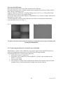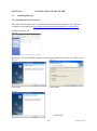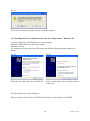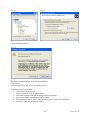
1
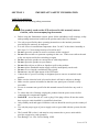
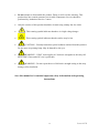
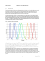
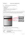
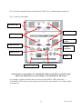
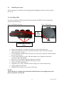
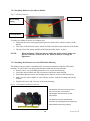
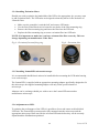
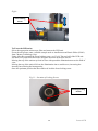
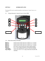
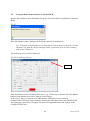
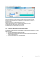
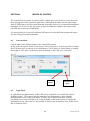
LumenLED Manual Version 1.00 Table of Contents SECTION 1 IMPORTANT SAFETY INFORMATION 3 1.1 IMPORTANT SAFETY INFORMATION 3 SECTION 2 5 2.1 2.2 2.3 LEDS & FLUORESENCE Introduction Switching Speeds and stability of LEDs Availability of new LEDs 5 6 6 SECTION 3 INSTALLATION 7 3.1 3.2 3.3 3.3.1 3.3.2 3.3.3 3.3.4 3.3.5 3.4 3.5 7 7 9 9 10 10 11 11 11 13 Identifying the parts of the LumenLED System LumenLED controller box connections and indicators Installing the system. Installing LEDs Installing Dichroics into Mirror Holder Installing the Dichroics in to the LED Main Housing Installing Excitation filters Installing LumenLED unit on microscope. Adjustments to LED Connecting the Interactive Control Centre (PS3J100). SECTION 4 4.1 4.1.2 4.1.3 4.1. Installing Software. Installing the Prior Communications Port for USB operation – Windows XP Installing the Prior Communications Port for USB operation – Windows Vista. Installing the Prior Communications Port for USB operation – Windows 7. SECTION 5 5.1 5.1.1 5.1.2 5.1.3 5.2 5.2.1 WORKING WITH LEDS Using the Interactive Control Centre to Control LED. Button functionality of PS3J100 Control of LED Intensity via PS3J100 Display Screen of PS3J100 Using the Prior Demo Software to Control LED. Control of LED Intensity via Prior Demo Software SECTION 6 6.1 6.2 6.3 6.4 INSTALLATION OF SOFTWARE MODES OF CONTROL Current Mode Light Mode TTL Commands Overdriven Zone 14 14 15 17 20 21 21 21 22 22 23 24 25 25 25 26 26 1 LumenLED SECTION 7 SOFTWARE COMMANDS 28 SECTION 7 REPLACEMENT & SPARE PARTS 30 SECTION 8 SERVICING 31 SECTION 9 TECHNICAL SPECIFICATIONS 31 SECTION 10 RETURNS AND REPAIRS 32 APPENDIX 1 LumenLED AND COMPATIBILITY MODE. 33 2 LumenLED SECTION 1 IMPORTANT SAFETY INFORMATION SAFETY WARNINGS Always observe the following safety precautions This symbol, used on the LED units and in this manual, means: Caution, refer to accompanying documents Before using the illumination system, please follow and adhere to all warnings, safety and operating instructions located on the product and in this User Manual. Use only as specified by these operating instructions or the intrinsic protection provided by the unit may be impaired. It is safe for use in an ambient temperature from 5 to 40°C with relative humidity to 80% up to 31°C decreasing linearly to 50%rH at 40°C. Do not expose the product to water or moisture while energised. Do not allow moisture to penetrate openings in the case. If this occurs allow the unit to dry out unpowered before switching on again Do not expose the product to extreme hot or cold temperatures. Do not expose the product to open flames. Do not allow objects to fall on or liquids to spill on the product. Do not replace detachable mains supply cords by inadequately rated cords. Do not cover or impede ventilation to this system. Do not stare into the light output of the LED units. Connect the AC power cord only to designated power sources as marked on the product. Make sure the electrical cord is located so that it will not be subject to damage. Make sure the system in installed so that the reaer panel power switch is easily accessible. For use in a manner not specified in this manual contact Prior before any work is done. To reduce the risk of damage, unplug the product from the power source before connecting the components together. DANGER - never alter the AC cord or plug. If the plug will not fit into the outlet, have a proper outlet installed by a qualified electrician. Only suitably rated and approved mains cord-sets should be used as per the country of use. Use only the proper type of power supply cord set (provided with the system) for this unit. The LumenLED is class 1 and must be only connected to a power outlet which provides a protective earth (ground). Fuse Rating T2A- 250v. Power Rating 150W. 3 LumenLED Do not attempt to disassemble the product. Doing so will void the warranty. This product does not contain consumer serviceable components. Service should be performed by Authorised Service Centres. Only the exterior of this product should be cleaned using a damp lint-free cloth. This warning symbol indicates that there is a high voltage danger. This warning symbol indicates that the surface may be hot. CAUTION – Possibly hazardous optical radiation emitted from this product. Do not stare at operating lamp. May be harmful to the eyes. WARNING – If PAT tester applies AC dielectric strength test, this may fail due to EMC filters and a DC test is preferable. WARNING – Do not repeat the use of dielectric strength testing as this may damage safety insulation. Save this manual as it contains important safety information and operating instructions 4 LumenLED SECTION 2 2.1 LEDS & FLUORESENCE Introduction Traditional method of microscope illumination involved the use of a white light source such as mercury or xenon arc lamps. These are broad spectrum lamps and require the use of optical filters to block out unwanted wavelengths. However no filter is 100% efficient meaning some unwanted light will always reach your specimen. A light emitting diode (LED) is a semiconductor device that emits a narrow band of light when a current is applied to it. The colour of emitted light depends upon the composition of the semiconducting material used and can range across the spectrum from near ultraviolet to infrared. Varying the composition of the semiconducting material used, by the introduction of impurities to the silicon, is known as Doping. FIG 1- Different LED wavelengths. Although the spectral output of an LED is more specific than a standard arc lamp, it may still be wide enough to require the addition of an excitation filter to optimise the band width for the particular wavelength. (Please see section 3.3.4 Installing Excitation Filters). It is important to match the correct LED with the appropriate filter sets, please see contact your local Prior office for advice. LED illumination has various advantages over traditional delivery method of illumination. With LED technology there is little heat generated allowing the illumination to be directly coupled to the microscope to maximise light while avoiding excessive heat transfer to the specimen. Excitation filters, if required can be mounted directly in front of the LED, avoiding the need for excitation filter wheels and therefore also avoiding unwanted vibration in the system. 5 LumenLED 2.3 Switching Speeds and stability of LEDs Typically a filter wheel and shutter system can switch between wavelengths in around 80milli seconds. This LumenLED will switch in micro seconds when connected via TTL (analogue control). The stability of light sources varies, but HBO bulb will decrease by 30-50% over 200 hours, a metal halide will decrease 30% over 2000hours. Both have short term stability issues. Included in the LumenLED is a closed loop feedback system to ensure the light is stable and reliably the same each time the unit is powered up. This closed loop feedback keeps the light the same no matter how long or short a time scale the system is measure over. LEDs can last for over 20,000hrs. 2.4 Availability of new LEDs New wavelengths and higher power LED are being generated all the time, if you have a specific application and cannot find the LED required, as your local prior office for more information. 6 LumenLED SECTION 3 3.1 INSTALLING YOUR SYSTEM Identifying the parts of the LumenLED System The controller consists of: 1 off, controller box. 1 off, RS232 Cable. 1 off, USB cable. 1 off Power cable, supplied suitable for you geographical area. 1 x Main Housing (either a four or two LED version). LED unit LED cables (one per LED Unit) The controller box may be of two variants, the vertical stack option or the horizontal stacking options, for the purposes of this manual we will use the vertical version in pictures and instruction below, however the instructions apply equally to the horizontal version. Fig 2 – Front of LumenLED Power Indicator Tx/RX indicator Status Indicator 3.2 LumenLED controller box connections and indicators The controller front face has 3 LED. POWER: TX RX: RX TX STATUS: Green Illumined: Power On Two Colour LED, RX receive and TX transmit communications Amber illuminated Green illuminated Red illuminated: Fault in system. 7 LumenLED The rear of the controller has the connections to LEDs, TTL, communications and power. Fig 3 – Back of LumenLED Extension Unit TTL In Connector LED Connector CAN Connector Socket COMs Connector TTL Out Connector USB Connector Fuses Power Switch Joystick Connector Note the above is an example of a LumenLED 4 LED system. TTL 3 and TTL4 plus LED 3 and LED4 ports are not available on a LumenLED 2 LED system It is possible to add an extension unit to convert a LumenLED 2 LED system into a LumenLED 4 LED system, please contact your local Prior representative (see contact details in section 10) 8 LumenLED 3.3 Installing the system. All the connectors are labelled, when plugging and unplugging connector always turn the power off. 3.3.1 Installing LEDs It is best to install the LEDs into the LED main housing (LDXXX) before installing the system to the microscope. Fig 4 – LED Main Housing Fig 5 – LED Cover LED Locking Screws Dichroic Mirror Locking Screws Ensure the controller is switched off and is not connected to the power. Connect the LED ports on the LumenLED controller to the LED units using the cables provided., see Fig 3 It is not important which LED connections are used on the Controller, but this should be noted for later use. Fix the round connector to the LED unit making sure to align the notch in the connectors and push together. Screw the outer casing to lock the connector in position. Remove any covers on the LED main housing, see Fig 5 Loosen the LED fixing screws. Align the grove in the LED unit with the fixing screw of the main housing. Gently push in the LED unit. Tighten LED Locking screw to secure LED units. NOTE The LED units are designed to be mounted with the shortest wavelength nearest the microscope frame. See Fig XX 9 LumenLED 3.3.2 Installing Dichroics into Mirror Holder Fig 7 – Dichroic Mirror Dichroic Mirror Mirror Fixing Spring Locating Notch To add a new dichroic mirror or to change one; Pull back the mirror fixing spring and place the mirror flat with the surface of the holder. The sides of the dichroic mirror should sit flush with the bottom and side of the hoder. Slowly release the spring and this will firmly hold the mirror in place. NOTE: When mounting a Dichoric mirror inside the holder always make sure that the reflective coated side of the Dichroic mirror is facing the lightsource. 3.3.3 Installing the Dichroics in to the LED Main Housing The dichroic mirror must be mounted in the corrected orientation inside the LED main housing. To aid for this a locating notch has been added to the mirror holder. Remove the 5 screws holding down the cover on the main housing. Insert the mirror holder into the relevant slot inside the main housing. Remember that the lowest wavelength mirror must be closest to the microscope. Make sure the mirror holder is seated firmly in place with the locating notch at the bottom. Replace the cover and 5 screws of the main housing. Fig 6 – Orientation of dichroic mirrors. The Dichroic mirrors must be mount in the correct order. The shortest wavelength must be closest to the microscope. The direction around indicated the direction of wavelengths from longest (ie Red) towards shortest (eg. Blue). 10 LumenLED 3.3.4 Installing Excitation filters Should you wish to optimise the bandwidth of the LED to the appropriate dye you may want to add excitation filters. The LED units are designed so that they allow for the inclusion of 25mm Ø filters. Make sure the controller is switched off, and remove LED units.. Use the Prior Filter Block tool to locate the two holes of the filter mounting ring. Remove the filter mounting ring and insert the filter into the LED unit. Replace the filter mounting ring to secure excitation filter into LED unit. NOTE: It is important to make sure you have orientated the filter correctly. This can change depending on manufacturer of the filter. Fig 8 – Excitation filter and fixing ring Fig 9 – Excitation filter 3.3.5 Installing LumenLED unit on microscope. It is recommended that Dichroic mirrors be installed before mounting the LED main housing on to a microscope. The LumenLED is supplied with an appropriate mounting adapter specifically designed to fit the microscope, the supplied mounting adapter will only fit the specified make of microscope. Adapters can be exchange should you wish to move the LumenLED onto another manufactures microscope. 3.3.6 Adjustments to LED. To optimise the performance of the LED it is possible to focus and centre each individual LED unit. The LumenLED system must be fully mounted onto the microscope and the appropriate microscope filters used for the relevant LED units before they can be correctly adjusted and the illumination optimised. 11 LumenLED Fig10 Focus Locking Screw To Focus the LED units; Select the appropriate microscope filter and turn on the LED unit. Focus the microscope onto a suitable sample such as Autofluorescent Plastic Slides (92001) from Chroma Technology Corp. Using Allen Key to undo the focus locking screw, see Fig10, The top half of the LED unit will now freely slide back and forth, along the direction of the blue arrows. Moving the top of the unit away from its base with spread the illumination across the field of view. Moving the top of the unit will focus the illumination into a smaller area, increasing the intensity but reducing the homogeneity. Once the optimum position has been achieved lock the focus locking screw. Fig 11 – Location of Locking Screws Centring Locking Screws 12 LumenLED To Centre the LED units; Select the appropriate microscope filter and turn on the LED unit. Focus the microscope onto a suitable sample such as Autofluorescent Plastic Slides (92001) from Chroma Technology Corp. Using an Allen Key unlock the 3 centring locking screws. (see Fig 11). The top half of the LED unit will freely move in a circular motion . Look at the image and check the flatness of illumination. Fig 12 shows 4 images with uneven illumination in each corner. Carefully adjust the position of the LED until you achieve a homogeneous illumination across the field of view. See Fig 13 Fig 12 – Examples of incorrect adjustment Fig 13 – Homogenous illumination To achieve the best results it may be necessary to repeat the above steps of focusing and centring the illumination. 3.3.7 Connecting the Interactive Control Centre (PS3J100). TheInteractive Control Centre (PS3J100), can provide control of the ON/OFF functions as well as the illumination intensity levels of each of the LED units installed. To Install the Interactive Control Centre (PS3J100) Ensure the system is switched off. Plug in the 9 way connector to either the RS232-1 (if this is not available use the RS232-2 connector). Power on the system. The Interactive Control Centre will detect the ProScan III controller, and associated peripheral devices and automatically configure the internal software. 13 LumenLED SECTION 4 4.1 INSTALLATION OF SOFTWARE Installing Software. 4.1.1 Installing the Prior Freeware All of the Prior hardware can be controlled with the PriorDemo software. The software is available to download from http://www.prioruk.com/downloadcentre/dc_software.html Content of the Zip file. Fig 14 Run Setup, if you are asked by windows to allow the program to run click yes, allow or run. Fig 15 Fig 16 Click Next Click Install Fig 17 Click Finish. 14 LumenLED Fig 18 Click Yes to restart your computer immediately Click No and restart you computer before using the program. 4.1.2 Installing the Prior Communications Port for USB operation – Windows XP. Copy the folder Prior PS3 USB Driver to your computer. Plug in the USB cable to the PS3 and computer. Switch the PS3 on. The computer will detect the new USB connection and the following popup window will appear. Fig 19 Fig 20 Select No, not at this time, then click NEXT. Select “Install from a list or specific location (advanced)” The following screen will be displayed. Browse to the location of Prior PS3 USB Driver folder on your desktop, click NEXT. 15 LumenLED Fig 21 Fig 22 Click Continue Anyway. Fig 23 The Prior Communications Port will now installed. Click Finish. Your computer may ask you to repeat this process. To Identify your Port Number Got to Start>control panel Select System from your control panel Select the hardware tab and then Select device manager. In device manager expand the PORTS option The connection label “Prior Communications port” is the PS3 connection. Note the COM port associated with it. 16 LumenLED 4.1.3 Installing the Prior Communications Port for USB operation – Windows Vista. Copy the folder Prior PS3 USB Driver to your computer. Plug in the USB cable to the PS3 and computer. Switch the PS3 on. The computer will detect the new USB connection and the following popup window will appear. Fig 24 Click Locate and install driver software. Fig 25 This window may appear at the bottom of your screen, wait. The following window will appear. 17 LumenLED Fig 26 Click I don‟t have the disc. Show me other options. The following window will appear. Fig 27 Click Browse my computer for driver software (Advanced). 18 LumenLED Fig 28 Click Browse and browse to the location of Prior PS3 USB Driver folder, click NEXT. Fig 29 Click Install this driver anyway. Click Finish. 19 LumenLED 4.1. Installing the Prior Communications Port for USB operation – Windows 7. Copy the folder Prior PS3 USB Driver to your computer. Plug in the USB cable to the PS3 and computer. Switch the PS3 on. The computer will detect the new USB connection and the following popup window will appear. Select Browse my Computer for driver Software. Browse to the location of the USB drivers Install this driver anyway The drivers will be installed. Device is now ready to use. 20 LumenLED SECTION 5 WORKING WITH LEDS The LumenLED can be controlled manually via the Interactive Control Centre or via software. 5.1 Using the Interactive Control Centre to Control LED. Fig 30 – PS3J100 Control Centre 2 3 1 4 5 6 Left Digipot Right Digipot 5.1.1 Button functionality of PS3J100 Button 1 Button 2 Button 3 Button 4 Button 5 Button 6 Left Digipot Right Digipot On/Off control of LED connected to LED Port 1 of controller. On/Off control of LED connected to LED Port 2 of controller. On/Off control of LED connected to LED Port 3 of controller. On/Off control of LED connected to LED Port 4 of controller Menu Button (only if connected to a Proscan III controller). Focus Control (only if connected to a Proscan III controller). Control of the Light Intensity Levels for selected wavelengths. Control of the Focus Levels. (only if connected to a Proscan III controller).. 21 LumenLED 5.1.2 Control of LED Intensity via PS3J100 The intensity of each LED and be set individually via the PS3J100 in 1% steps from 0% to 100%. Press and hold down relevant LED button (eg Buttons 1-4). Rotate Left Digipot clockwise to increase intensity, anticlockwise to decrease intensity. Release the relevant LED button (eg Buttons 1-4). To Turn off LED push the relevant button (eg Button 1-4), to turn back on press the same button again. 5.1.3 Display Screen of PS3J100 Fig 31 – Display of PS3J100 The available wavelengths to control from the PS3J100 can be seen on the display screen of the PS3J100. ● ○ 100% 405 460 N/A LED OFF LED ON LED405 Intensity set at 100% Wavelength of LED attached to Port 1 of LumenLED controller. Wavelength of LED attached to Port 2 of LumenLED controller. No LED attached to that particular Port. 22 LumenLED 5.2 Using the Prior Demo Software to Control LED. Run the Prior Software from Startmenu>Program> Prior Scientific>Visual Basic>Controller Demo Fig 32 Enter the number of the COM port the ProScan controller is attached on. Tip: To find the virtual COM port use Startmenu>Control panel>system the click the Hardware tab then the Device manager button, expand the ports section to identify and virtual COM ports. The Following screen will be displayed. Fig 33- PriorDemo software LEDs Only attached accessory sections will be active, e.g., if there are no shutters all of the Shutter buttons in the Shutter area will be light grey and inactive. In the Fig 33 above, no other device other than the LEDs have been connected. Control of the LED units can be found by clicking the LED Menu and select SHOW LEDS. The following control box will appear for each wavelength attached to the system, in the example LED 447nm. 23 LumenLED Fig 34 – PriorDemo LED Control Module. From this control box several options are available for the associated LED unit. Selection of LED operation mode, Light Mode or Current Mode (see section 5) Turn ON or OFF. Intensity levels set in 1% intervals from 0% to 100%. Control of the LED units via TTL Triggers can be turned ON or OFF. The pulse time for LED on time via the TTL signal. The status of the TTL trigger can be set, see Fig 34. 5.2.1 Control of LED Intensity via Prior Demo Software The intensity of each LED and be set individually via the Prior Demo software in 1% steps from 0% to 100%. Left click and hold mouse on the Power Bar. Mouse Power bar towards the left (0%) to decrease power and towards the right (100%) to increase power. To turn of LED use the On / Off radial buttons. 24 LumenLED SECTION 6 MODES OF CONTROL The LumenLED can operate in various modes, and the user is freely able to select the mode most appropriate to their particular application. Although in the short term the light output from an LED tends to be more stable than that from other sources, it is somewhat temperature dependent. To correct for this, the option of optical feedback to stabilize the output is also provided, this is known as Light Mode It is also possible to set up each individual LED unit to work in different operational modes. See list of HyperTerminal commands. 6.1 Current Mode Current Mode is the default setting for the LumenLED system. In thix mode the system is able to run at up to 100% of its power. It is also possible to enable the LED units to be overdriven up to a maximum of 120%, however if this feature is enabled the length of „ON‟ time is restricted to prevent damage to the LED. (see section 6.4) Fig 35 100% Power 6.2 Overdriven Zone Light Mode In Light Mode the light intensity of the LED can be controlled via a closed loop optical feedback system. This ensures that the intensity of the illumination is kept constant throughout the course of the experiment. To allow for the optical system to work the maximum power of the LED has to be reduced slightly to allow the system to regulate the illumination levels. Therefore it is not possible to work in the Overdriven zone, so the Power Bar is limited to 100%. 25 LumenLED Fig 36 6.3 TTL Commands TTL commands can operate in either Current mode or Light mode. For each LED unit there is one TTL BNC connector. It is important to note that Trigger commands override any software commands. Therefore if the software has switched the LED off but the Trigger is enabled and the correct state (eg High) defined then the LED will come on despite what the software says. The length of time the LED is ON depends of the time specified in the PULSE TIME box. This value is set in milliseconds and the time set is not limited assuming the LED is not running in the Overdriven Zone. 6.4 Overdriven Zone The Overdriven Zone is available for applications where a high light intensity is required for short burst of time. When the power is set to greater than 100% the on time of the LED is limited to a maximum of 20ms. The subsequent OFF time is calculated as a duty cycle percentage from the power setting. Eg. If the power is at 120% then the OFF time has to be a minimum of 4ms. The restriction in the ON time is automatically enabled to protect the LED from damage due to the high power input in overdriven mode. 26 LumenLED SECTION 7 SOFTWARE COMMANDS Command Argument s Response Description LED n, NONE, END, Or FLUOR=UV LAMBDA=405 SERIAL-12345 END Queries the information about LED n LED,COMP n, 0,1 LED,n, MODE, a n,L,C 0, C,L LED, COMP,0 Standard mode. LED,COMP,1 Emulation Mode LED,COMP give the mode status. a = L for Light Mode a = C for Current Mode LED,n,MODE responds with operational mode „C‟ or „L‟ LED,n, STATE,a n 0,1 Queries the state of the LED Responds 1 (on), 0 (off) LED,n, POWER n a,b LED,n, POWER,p n,p 0 Queries the LED Power a = selected operating power b = percentage by which LED can be over powered. Eg. 100,120 Sets the LED power to „p‟ percent. The value of „p‟ can be up to the max percent the LED can be over powered (ie „b‟above). LED,n,TTL n LED,n,TTL, E n H,E,L,D,a,b Queries the current TTL settting. H = Trigger High E = Trigger Enabled L = Trigger Low D = Trigger Disabled a = msec ON time b = msec OFF time 0 Enables Trigger LED,n,TTL, D n 0 Disables Trigger 27 LumenLED LED,n,TTL, H n 0 LED is on when TTL is HIGH LED,n,TTL, L n 0 LED is on when TTL is LOW LED,n,TTL, T,on n Sets the LED „ON‟ time for pulsing. Note if power <=100% on times are not restricted. If power >100% on times are restricted. Examples of Typical Commands; Example 1 Turns LED 1 ON and OFF via software commands at 100% power. LED,1,POWER,100 LED1,STATE,1 LED,1,STATE,0 Example 2 sets power to 100% turns on LED turns off LED. Turns LED 1 ON and OFF via software commands at maximum power LED,1,POWER query power setting. Software response - 100,120 two values returned by controller. The second is the maximum power. LED,1,POWER,120 Sets power to 120% LED,1,TTL the LED cannot be permanently on when over driving the power. Therefore query the pulse time R,D,200,40 Controller switches to rising edge mode with on time of 20ms and then controller switches off automatically for 4ms before another command accepted. LED,1,STATE,1 Start single pulse. 28 LumenLED SECTION 8 REPLACEMENT & SPARE PARTS Additional LED Units LED 365 Single LED Unit 365nm LED385 Single LED Unit 385nm LED405 Single LED Unit 405nm LED447 Single LED Unit 447nm LED460 Single LED Unit 460nm LED505 Single LED Unit 505nm LED525 Single LED Unit 525nm LED590 Single LED Unit 590nm LED625 Single LED Unit 625nm LED660 Single LED Unit 660nm Additional Dichroic Mirrors. LDD410 Long pass filter 410nm LDD495 Long pass filter 495nm LDD552 Long pass filter 552nm LDD593 Long pass filter 592nm 29 LumenLED SECTION 9 SERVICING This equipment contains no user-serviceable parts. Refer all repairs to qualified service personnel. Opening the product voids the warranty. For approved service outlets contact your nearest Prior office.. SECTION 10 TECHNICAL SPECIFICATIONS This equipment is for indoor use and is designed to be safe within an ambient temperature range 5 to 40°C with maximum relative humidity of 80%; relative humidity derated linearly to 50%rh above 31ºC Dry weight 6.1Kg Dimensions (Not including tip support bracket) : 174mm (W) x 130mm (H) x 250mm (D). Supply voltage 100v to 240v, 50Hz to 60Hz. 30 LumenLED SECTION 11 RETURNS AND REPAIRS Should you experience problems with your LumenLED System and want to send it back for service, warranty or otherwise, a Return Material Authorisation (RMA) number must be obtained from the appropriate Prior Scientific office before returning any equipment. For North and South America contact Prior Scientific Inc., for Japan contact Prior KK, for Germany, Austria and Switzerland contact Prior GmbH and for the all other countries contact Prior Scientific Instruments Limited on the telephone numbers shown below. Prior Scientific Instruments Ltd, Unit 4, Wilbraham Road, Fulbourn, Cambridge, ENGLAND, CB1 5ET Tel: 01223 881711 Fax: 01223 881710 email: [email protected] Prior Scientific Inc. 80 Reservoir Park Drive, Rockland, MA 02370-1062 USA Tel: 781 878 8442 Fax: 781 878 8736 email: [email protected] Prior Scientific GmbH Wildenbruchstr. 15 D-07745 Jena GERMANY Tel: +49 (0)3641 675 650 Fax: +44 (0)3641 675 651 email: [email protected] Prior Scientific KK 3F Metlife Kabuticho Bldg 5-1 Nihonbashi Kabuto-Cho Chuo-Ku Tokyo 103-0026 JAPAN Tel: +81 (0) 3 5847 8213 Fax: +81 (0) 3 5847 7901 email: [email protected] 31 LumenLED APPENDIX 1 LumenLED and Compatibility Mode. There is an option to run the LumenLED in Compatibility mode. This mode allows the system to emulate a Proscan III with filter wheel and shutter capability, and therefore makes the system compatible with software currently supporting Prior filter wheels and shutters. LED,COMP,1 When changing from the default standard mode to the compatibility mode the system must be restarted. LED wavelength selection will emulate one filter wheel and LED intensity level will emulate another filter wheel. The will be one filter wheel position left to add an additional physical filter wheel. Eg. Filter Wheel 1 - HF110 filter wheel. Filter Wheel 2 - LED wavelength selection. Filter Wheel 3 – LED Intensity Level Selection. Note as the Prior filters wheels a designed with 10 positions the possible intensity levels will be as follows; 1 = 100% 2 = 95% 3 = 90% 4 = 85% 5 = 80% 6 = 75% 7 = 70% 8 = 65% 9 = 50% 10 = 25% The ON/OFF function of each LED will emulate the Prior shutter. If a physical shutter is present also select one of the available free shutter ports for the LumenLED. Eg. Shutter 1 – HF202 shutter. Shutter 2 – LumenLED ON/OFF function Shutter 3 - Free The Open command of the shutter will turn On the LED unit currently selected in the filter wheel. The Close command of the shutter will turn OFF the LED unit currently selected in the filter wheel. 32 LumenLED LED Filter Wheel Emulation Commands Command Argument s Response Description 7 w, f R or a number. If LED is fitted E,17 will be returned. w defines the LED wavelength number 1,2 or3. f is defined below. If f is a number, command moves filter LED w to LED position f. If f is „N‟, command moves LED w to next LED. If f is „P‟, command moves LED wheel w to previous LED. If f is „F‟, command reports current LED position on If f is „H‟, command performs a home routine. No effect. 7 0,f1,f2,f3 R 7 W,T,P Text 7 W,T,P, text R The first parameter (zero) indicates all LED; the three subsequent parameters f1 f2 and f3 are the target positions for LED1, 2 and 3 respectively. LED not fitted or invalid filter wheel positions are ignored. This feature is only available in COMP 0 mode. Displays tag text for LED w at position p. 7,1,T,3 will respond with text for LED 1 position 3. Writes text to memory for LED W and Position P. 7,1,T,3,Dapi will set the tag for filter wheel 1 position 3 to “Dapi” Tags are 6 characters log and are displayed in control centre display. 33 LumenLED LED Shutter Emulation Commands Command Argument s Response Description 8 s,c[,t] Turns ON or OFF the LED s (value „1‟ „2‟ or „3‟), if c is 0 the LED is ON, 1 it is OFF. The optional argument t is used to ON/OFF the LED for a time t milliseconds. 8 0,s1,s2,s3 R If LED s is not fitted E,20 will be returned 0 8 s Shutter s c If LED s is not fitted E,20 will be returned Text string First parameter is a zero. Subsequent parameters define the startup state of LED s1,s2 and s3 respectively. if s1 is 0 then LED1 is ON, 1 it is OFF etc. Default state is all LED closed. Returns status c of LED s Prints information about LED„s‟ (s is a value between 1 and 3). The information end is always a line saying END. This allows for the addition of extra fields of information without effecting application software. Users should always read lines until the END is seen in order to maintain compatibility. Example SHUTTER_1 = NORMAL DEFAULT_STATE=CLOSED END 34 LumenLED