1
CHAPTER12 ■ BEGINNING ELECTRONICS
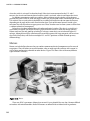
Those motors with built-in gear boxes are called gearheads and generally run at much slower speeds,
but increase the total available torque that the motor can provide. Solenoids are a type of motor that
causes a shaft to contract or expand, creating linear movement when electricity is applied.
Different types of motors will have different types of characteristics. The ratings that we should be
most concerned with are the motor’s voltage and stall current. The rated voltage of a motor is for peak
efficiency, although we can generally power a motor with a little more or less than it is rated for. The
motor’s stall current is the amount of amps the motor will pull when some force has caused the motor to
stop moving. While the motor will generally run well below its stall current rating, our available power
and switching mechanisms need to be rated for the greater stall current with a little room to spare to be
on the safe side.
Radial motors are often also rated in revolutions per minute or RPM that tell us how fast the motor
will spin. The speed of the motor is not as important for stepper or servo motors, which are more
concerned with the positional accuracy, specified in degrees per step and total steps per revolution.
Motors will also usually be rated for its pulling force or torque. This is measured by the amount of force
the motor can apply at a given distance from the center of the motor’s shaft. This rating is far from
standard with measurements in oz/in, or ounces per inch; lb/ft, or pounds per foot; g/cm, or grams per
centimeter; and even N/cm, for newtons per centimeter.
While we could continue to list category after category of components, we should probably stop
here and talk about how we can use these components in our prototypes.
Reading Schematics
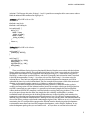
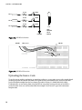
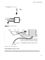
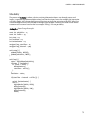
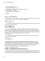
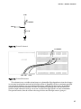
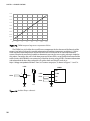
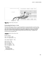
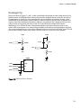
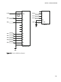
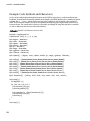
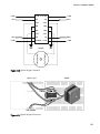
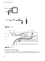
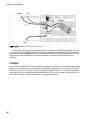
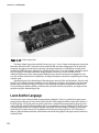
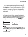
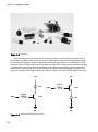
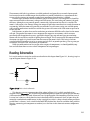
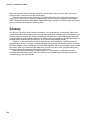
Let’s revisit our basic circuit that we discussed earlier in this chapter from Figure 12-1, drawing it up in a
type of diagram shown in Figure 12-10.
SWITCH
+
+9 VDC
LAMP
Figure 12-10. Basic circuit schematic
This drawing, an exact representation of the gadget in Figure 12-1, is a fairly standard wiring
diagram called a schematic. We’ve been using them throughout this book, but you might want to know
a little more about how they work. Schematics are a bit pictographic, like something out of the caves of
Lascaux, but it shows us clearly how the circuit described earlier is connected. Once we know what the
somewhat standardized symbols mean, in that a squiggle in a circle is a lamp, a bunch of long and short
parallel lines is a battery, and a switch kind of looks like a broken line, then we can follow along with the
drawing, connecting one component to another just as the lines in the schematic connect components
together.
231