1
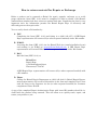
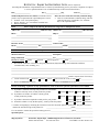
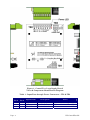
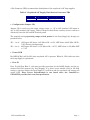
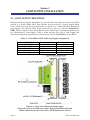
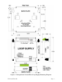
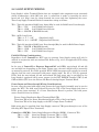
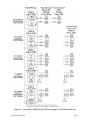
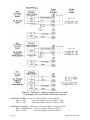
Product Information Package
PIP-ControlWaveLS
July, 2006
ControlWave Loop Power Supply
ControlWave LOOP POWER SUPPLY
PRODUCT INSTALLATION GUIDE
For the following ControlWave Series
Products: MICRO, EFM, GFC,
ExpressPAC & Express
www.EmersonProcess.com/Bristol
IMPORTANT! READ INSTRUCTIONS BEFORE STARTING!
Be sure that these instructions are carefully read and understood before any
operation is attempted. Improper use of this device in some applications may result in
damage or injury. The user is urged to keep this book filed in a convenient location for
future reference.
These instructions may not cover all details or variations in equipment or cover
every possible situation to be met in connection with installation, operation or maintenance. Should problems arise that are not covered sufficiently in the text, the purchaser is advised to contact Bristol for further information.
EQUIPMENT APPLICATION WARNING
The customer should note that a failure of this instrument or system, for
whatever reason, may leave an operating process without protection. Depending upon
the application, this could result in possible damage to property or injury to persons.
It is suggested that the purchaser review the need for additional backup equipment
or provide alternate means of protection such as alarm devices, output limiting, failsafe valves, relief valves, emergency shutoffs, emergency switches, etc. If additional
in-formation is required, the purchaser is advised to contact Bristol .
RETURNED EQUIPMENT WARNING
When returning any equipment to Bristol for repairs or evaluation, please note
the following: The party sending such materials is responsible to ensure that the
materials returned to Bristol are clean to safe levels, as such levels are defined and/or
determined by applicable federal, state and/or local law regulations or codes. Such
party agrees to indemnify Bristol and save Bristol harmless from any liability or
damage which Bristol may incur or suffer due to such party's failure to so act.
ELECTRICAL GROUNDING
Metal enclosures and exposed metal parts of electrical instruments must be
grounded in accordance with OSHA rules and regulations pertaining to "Design
Safety Standards for Electrical Systems," 29 CFR, Part 1910, Subpart S, dated: April
16, 1981 (OSHA rulings are in agreement with the National Electrical Code).
The grounding requirement is also applicable to mechanical or pneumatic instruments that include electrically-operated devices such as lights, switches, relays,
alarms, or chart drives.
EQUIPMENT DAMAGE FROM ELECTROSTATIC DISCHARGE VOLTAGE
This product contains sensitive electronic components that can be damaged by
exposure to an electrostatic discharge (ESD) voltage. Depending on the magnitude
and duration of the ESD, this can result in erratic operation or complete failure of the
equipment. Read supplemental document S14006 at the back of this manual for
proper care and handling of ESD-sensitive components.
Bristol 1100 Buckingham Street, Watertown, CT 06795
Telephone (860) 945-2200
WARRANTY
A.
Bristol warrants that goods described herein and manufactured by Bristol are free
from defects in material and workmanship for one year from the date of shipment
unless otherwise agreed to by Bristol in writing.
B.
Bristol warrants that goods repaired by it pursuant to the warranty are free from
defects in material and workmanship for a period to the end of the original warranty
or ninety (90) days from the date of delivery of repaired goods, whichever is longer.
C.
Warranties on goods sold by, but not manufactured by Bristol, are expressly limited
to the terms of the warranties given by the manufacturer of such goods.
D.
All warranties are terminated in the event that the goods or systems or any part
thereof are (i) misused, abused or otherwise damaged, (ii) repaired, altered or
modified without Bristol's consent, (iii) not installed, maintained and operated in
strict compliance with instructions furnished by Bristol, or (iv) worn, injured or
damaged from abnormal or abusive use in service time.
E.
THESE WARRANTIES ARE EXPRESSLY IN LIEU OF ALL OTHER
WARRANTIES EXPRESS OR IMPLIED (INCLUDING WITHOUT LIMITATION
WARRANTIES AS TO MERCHANTABILITY AND FITNESS FOR A PARTICULAR
PURPOSE), AND NO WARRANTIES, EXPRESS OR IMPLIED, NOR ANY
REPRESENTATIONS, PROMISES, OR STATEMENTS HAVE BEEN MADE BY
BRISTOL UNLESS ENDORSED HEREIN IN WRITING. FURTHER, THERE ARE
NO WARRANTIES WHICH EXTEND BEYOND THE DESCRIPTION OF THE
FACE HEREOF.
F.
No agent of Bristol is authorized to assume any liability for it or to make any written
or oral warranties beyond those set forth herein.
REMEDIES
A.
Buyer's sole remedy for breach of any warranty is limited exclusively to repair or
replacement without cost to Buyer of any goods or parts found by Seller to be
defective if Buyer notifies Bristol in writing of the alleged defect within ten (10) days
of discovery of the alleged defect and within the warranty period stated above, and if
the Buyer returns such goods to Bristol's Watertown office, unless Bristol's Watertown office designates a different location, transportation prepaid, within thirty (30)
days of the sending of such notification and which upon examination by Bristol
proves to be defective in material and workmanship. Bristol is not responsible for
any costs of removal, dismantling or reinstallation of allegedly defective or defective
goods. If a Buyer does not wish to ship the product back to Bristol, the Buyer can
arrange to have a Bristol service person come to the site. The Service person's
transportation time and expenses will be for the account of the Buyer. However,
labor for warranty work during normal working hours is not chargeable.
B.
Under no circumstances will Bristol be liable for incidental or consequential
damages resulting from breach of any agreement relating to items included in this
quotation, from use of the information herein or from the purchase or use by Buyer,
its employees or other parties of goods sold under said agreement.
How to return material for Repair or Exchange
Before a product can be returned to Bristol for repair, upgrade, exchange, or to verify
proper operation, form (GBU 13.01) must be completed in order to obtain a RA (Return
Authorization) number and thus ensure an optimal lead time. Completing the form is very
important since the information permits the Bristol Repair Dept. to effectively and
efficiently process the repair order.
You can easily obtain a RA number by:
A. FAX
Completing the form (GBU 13.01) and faxing it to (860) 945-3875. A BBI Repair
Dept. representative will return call (or other requested method) with a RA number.
B. E-MAIL
Accessing the form (GBU 13.01) via the Bristol Web site (www.bristolbabcock.com)
and sending it via E-Mail to [email protected]. A BBI Repair Dept.
representative will return E-Mail (or other requested method) with a RA number.
C. Mail
Mail the form (GBU 13.01) to
Bristol Inc.
Repair Dept.
1100 Buckingham Street
Watertown, CT 06795
A BBI Repair Dept. representative will return call (or other requested method) with
a RA number.
D. Phone
Calling the Bristol Repair Department at (860) 945-2442. A Bristol Repair Department representative will record a RA number on the form and complete Part I, then
send the form to the Customer via fax (or other requested method) for Customer
completion of Parts II & III.
A copy of the completed Repair Authorization Form with issued RA number should be included with the product being returned. This will allow us to quickly track, repair, and
return your product to you.
Bristol Inc. Repair Authorization Form
(off-line completion)
(Providing this information will permit Bristol Inc. to effectively and efficiently process your return. Completion is required
to receive optimal lead time. Lack of information may result in increased lead times.)
Date___________________
RA #___________________SH_
Please be aware of the Non warranty standard charge:
• There is a $100 minimum evaluation charge, which is
applied to the repair if applicable (√ in “returned”
B,C, or D of part III below)
Standard Repair Practice is as follows: Variations to this is
practice may be requested in the “Special Requests” section.
• Evaluate / Test / Verify Discrepancy
• Repair / Replace / etc. in accordance with this form
• Return to Customer
Part I
Line No.____________
Please complete the following information for single unit or multiple unit returns
Address No.
(office use only) Address No.
(office use only)
Bill to :
Ship to:
Purchase Order:
Contact Name:____________________________________
Phone:
Fax:
Part II
E-Mail:
Please complete Parts II & III for each unit returned
Model No./Part No.
Description
Range/Calibration
S/N
Reason for return :
1.
Failure
Upgrade
Verify Operation
Other
Describe the conditions of the failure (Frequency/Intermittent, Physical Damage, Environmental Conditions,
Communication, CPU watchdog, etc.)
(Attach a separate sheet if necessary)
2.
Comm. interface used:
3.
What is the Firmware revision? _____________________
Standalone
RS-485
Ethernet
Other:______________
Modem (PLM (2W or 4W) or SNW)
What is the Software &version?
Part III If checking “replaced” for any question below, check an alternate option if replacement is not available
A. If product is within the warranty time period but is excluded due
to Bristol’s warranty clause, would you like the product:
repaired
returned
replaced
scrapped?
B. If product were found to exceed the warranty period,
would you like the product:
repaired
returned
replaced
scrapped?
C. If product is deemed not repairable would you like your product:
returned
replaced
scrapped?
D. If Bristol is unable to verify the discrepancy, would you like the product:
returned
replaced
*see below?
* Continue investigating by contacting the customer to learn more about the problem experienced? The person to contact
that has the most knowledge of the problem is:
______________________________ phone_____________________
If we are unable to contact this person the backup person is: _________________________ phone_____________________
Special Requests: ____________________________________________________________________________________
____________________________________________________________________________________________________
Ship prepaid to:
Bristol Inc., Repair Dept., 1100 Buckingham Street, Watertown, CT 06795
Phone: 860-945-2442
Fax: 860-945-3875
Form GBU 13.01 Rev. B 04/11/06
Bristol
Training
GET THE MOST FROM YOUR BRISTOL
BABCOCK INSTRUMENT OR SYSTEM
•
Avoid Delays and problems in getting your system on-line
•
Minimize installation, start-up and maintenance costs.
•
Make the most effective use of our hardware and software.
•
Know your system.
As you know, a well-trained staff is essential to your operation. Bristol Inc. offers a full
schedule of classes conducted by full-time, professional instructors. Classes are offered
throughout the year at three locations: Houston, Orlando and our Watertown, CT
headquarters. By participating in our training, your personnel can learn how to install,
calibrate, configure, program and maintain any and all Bristol products and realize the full
potential of your system.
For information or to enroll in any class, contact our training department in Watertown at
(860) 945-2343. For Houston classes, you can also contact our Houston office, at (713) 6856200.
A Few Words About Bristol Inc.
For over 100 years, Bristol® has been providing innovative solutions for the measurement
and control industry. Our product lines range from simple analog chart recorders, to
sophisticated digital remote process controllers and flow computers, all the way to turnkey
SCADA systems. Over the years, we have become a leading supplier to the electronic gas
measurement, water purification, and wastewater treatment industries.
On off-shore oil platforms, on natural gas pipelines, and maybe even at your local water
company, there are Bristol Inc. instruments, controllers, and systems running year-in and
year-out to provide accurate and timely data to our customers.
Getting Additional Information
In addition to the information contained in this manual, you may receive additional assistance in using this product from the following sources:
Help Files / Release Notes
Many Bristol software products incorporate help screens. In addition, the software typically
includes a ‘read me’ release notes file detailing new features in the product, as well as other
information which was available too late for inclusion in the manual.
Contacting Bristol Inc. Directly
Bristol's world headquarters is located at 1100 Buckingham Street, Watertown,
Connecticut 06795, U.S.A.
Our main phone numbers are:
(860) 945-2200
(860) 945-2213 (FAX)
Regular office hours are Monday through Friday, 8:00AM to 4:30PM Eastern Time,
excluding holidays and scheduled factory shutdowns. During other hours, callers may leave
messages using Bristol's voice mail system.
Telephone Support - Technical Questions
During regular business hours, Bristol's Application Support Group can provide telephone
support for your technical questions.
For technical questions about TeleFlow products call (860) 945-8604.
For technical questions about ControlWave call (860) 945-2394 or (860) 945-2286.
For technical questions regarding Bristol’s OpenEnterprise product, call (860) 945-3865
or e-mail: [email protected]
For technical questions regarding ACCOL products, OpenBSI Utilities, UOI and all other
software except for ControlWave and OpenEnterprise products, call (860) 945-2286.
For technical questions about Network 3000 hardware, call (860) 945-2502.
You can e-mail the Application Support Group at: [email protected]
The Application Support Group maintains an area on our web site for software updates and
technical information. Go to: www.bristolbabcock.com/services/techsupport/
For assistance in interfacing Bristol hardware to radios, contact Bristol’s Communication
Technology Group in Orlando, FL at (407) 629-9463 or (407) 629-9464.
You can e-mail the Communication Technology Group at:
[email protected]
Telephone Support - Non-Technical Questions, Product Orders, etc.
Questions of a non-technical nature (product orders, literature requests, price and delivery
information, etc.) should be directed to the nearest sales office (listed on the rear cover of
this manual) or to your Bristol-authorized sales representative.
Please call the main Bristol Inc. number (860-945-2200) if you are unsure which office
covers your particular area.
Visit our Site on the World Wide Web
For general information about Bristol Inc. and its products, please visit our site on the
World Wide Web at: www.bristolbabcock.com
Training Courses
Bristol’s Training Department offers a wide variety of courses in Bristol hardware and
software at our Watertown, Connecticut headquarters, and at selected Bristol regional
offices, throughout the year. Contact our Training Department at (860) 945-2343 for course
information, enrollment, pricing, and scheduling.
PIP-ControlWaveLS
ControlWave Loop Supply
Part Numbers 400095-01-7, 721708-01-3 & 721708-02-1
TABLE OF CONTENTS
Section
Title
Page #
Section 1 – LOOP SUPPLY INTRODUCTION
1.1
1.2
GENERAL DESCRIPTION..................................................................................................... 1
LOOP SUPPLY COMPONENT IDENTIFICATION............................................................. 1
Section 2 – LOOP SUPPLY INSTALLATION
2.1
2.2
LOOP SUPPLY MOUNTING ................................................................................................. 4
LOOP SUPPLY WIRING ........................................................................................................ 6
Field I/O Wiring Considerations ...................................................................................... 6
Power Input and Pass-through Wiring Considerations.................................................. 6
Section 3 – SPECIFICATIONS
3.1
3.2
3.3
3.3.1
3.3.2
3.3.3
3.4
3.5
OPERATING SPECIFICATIONS......................................................................................... 10
ENVIRONMENTAL SPECIFICATIONS............................................................................. 10
CONNECTORS ...................................................................................................................... 11
Terminal Block TB1............................................................................................................... 11
Terminal Block TB3............................................................................................................... 11
Terminal Block TB2............................................................................................................... 11
PART NUMBERS .................................................................................................................. 11
DIMENSIONS........................................................................................................................ 11
PIP-ControlWaveLS
1
Table Of Contents
Section 1
LOOP SUPPLY INTRODUCTION
1.1 GENERAL DESCRIPTION
Bristol’s ControlWave Loop Power Supply (herein referred to as the “Loop Supply”),
provides regulated and isolated 24Vdc power outputs that can be used to power field
devices such as transmitters or non-isolated I/O circuits that are used in conjunction with
ControlWave MICRO, EFM, GFC, Express or Express PAC units. Encapsulated Loop
Supply’s, i.e., those with the printed circuit board (PCB) secured to a Power Supply Back
Plate Bracket and protected by a Power Supply Board Cover, may be mounted directly to a
panel or to a 35mm DIN Rail while the PCB only version can be Snap Track mounted.
Loop Supply’s provide 24Vdc field power distribution via four pairs of wiring terminals
provided on Terminal Block TB2. Additionally, Loop Supply’s are user configured via
Jumper JP1 to operate in conjunction with either a nominal bulk 12Vdc input (with an
input range of +9 to +30Vdc) or a nominal bulk 24Vdc input (with an input range of +19 to
+30Vdc). Loop Supply’s have been designed to provide the following features:
•
•
•
•
•
4 Loop Power Terminals pairs provide field device wiring flexibility and convenience.
9 - 30 Vdc bulk power input range accommodated installation flexibility
Bulk power input can be applied to either of the three-terminal connectors (with one
Terminal Block accommodating input wiring while the other may accommodate nonisolated power pass-through that is used to power the ControlWave MICRO
(Process Automation Controller), ControlWave EFM (Electronic Flow Meter)
ControlWave GFC (Gas Flow Computer), Express (Remote Terminal Unit), or
Express PAC (Process Automation Controller/Remote Terminal Unit).
Direct Panel, 35mm DIN Rail or Snap Track Mounting accommodated
Small size minimizes panel space requirements
1.2 LOOP SUPPLY COMPONENT IDENTIFICATION
Loop Supply components that the user should become familiar with are discussed herein.
These components include Connectors TB1, TB2 and TB3, Configuration Jumper JP1, the
Power LED, and Fuse F1.
• Terminal Blocks
Loop Supply’s are provided with three Terminal Blocks which accommodate up to #16 AWG
size wire. Terminal Block Connections are provided in Tables 1 and 2.
.
Terminal Block TB1 typically acts as the interface for the bulk 9 to 30 Vdc input power. In
some cases, TB1 may be used as the bulk dc power pass-through interface to an associated
RTU in lieu of Terminal Block TB3. It should be noted that TB1 & TB3 can be used for
Input Power or Power Pass-through with one accommodating input while the other may
accommodate pass-through, e.g. if TB1 was used to interface bulk Input Power, than TB3
could be used to accommodate Power Pass-through, or vise versa.
PIP-ControlWaveLS
Page - 1
Figure 1 - ControlWave Loop Supply Board
Views & Component Identification Diagram
Table 1 - Input/Pass-through Power Connectors – TB1 & TB3
TB1
Pin #
1
2
3
Page - 2
TB3
Pin #
3
2
1
Signal Name
VIN
RET
CHASSIS
Description
9 to 30 +Vdc power
9-30 Vdc Return
Chassis Ground
Notes
Input or Non-fused Throughput
Input or Non-fused Throughput
PIP-ControlWaveLS
8-Pin Connector (TB2) accommodates distribution of the regulated +24V loop supplies.
Table 2 - Regulated 24V Supply Distribution Connector TB2
TB2 Pin #
1, 3, 5, 7
2, 4, 6, 8
Signal Name
+24V
24V Return
Description
Regulated +24Vdc
Reg. 24V Return
• Configuration Jumper JP1
Jumper JP1 is used to set the input voltage range, i.e., 9V to 30V (nominal 12V input) or
19V to 30V (nominal 24V input). Under Voltage Lockout Point circuitry sources current to
affectively lower the ON and OFF switch points.
The nominal setting operating range switch points for the Loop Supply (by design) are
provided below.
JP1 - 1 to 2:
JP1 - 2 to 3:
12V Input: ON above 8.4V (Max. ON = 8.8V), OFF below 8.24V (Min. OFF =
7.8V) (Factory Configuration)
24V Input: ON above 18.8V, (Max. ON = 19.7V), OFF below 18.4V (Min. OFF
= 17.4V
• Power LED
Red LED (CR10) will be ON when regulated 24V is present. When lit, CR10 indicates that
the Loop Supply is operational.
• Fuse F1
Fuse F1 (2A Slow Blow 5 x 20 mm) provides protection for the LOOP Supply and the associated field I/O (powered by Loop Supply). If a short circuit should occur in I/O field
wiring or circuitry within the Loop Supply, F1 will blow and the regulated 24V output will
switch OFF. Note: Power Pass-through is not fused since the ControlWave
GFCs/RTUs provide their own fuse protection.
PIP-ControlWaveLS
Page - 3
Section 2
LOOP SUPPLY INSTALLATION
2.1 LOOP SUPPLY MOUNTING
Encapsulated Loop Supply Assemblies are provided with the printed circuit board (PCB)
secured to a Power Supply Back Plate Bracket and protected by a Power Supply Board
Cover. These units may be mounted directly to a panel or to a 35mm DIN Rail. Board only
Loop Supply’s are typically Snap Track mounted (as is the case with the ControlWave
EFM). Figure 2 shows a Snap Track Mounted unit while Figure 3 provides dimensions for
the “Encapsulated” Loop Supply. Table 3 below provides the type of Loop Supply and
mounting arrangement typically associated with the various ControlWave series RTUs.
Table 3 - ControlWave RTU and Loop Supply Assignments
ControlWave Series
ControlWave MICRO
ControlWave EFM
ControlWave GFC
ControlWave Express
ControlWave ExpressPAC
Loop Supply Type
Encapsulated
Snap Track Mounted
Snap Track Mounted
Encapsulated
Snap Track Mounted
Mounting Notes
Externally
Internally
Internally
Externally
Internally
Figure 2 - Snap Track Mounted Loop Supply
(Typically used in Conjunction with a Power Distribution Board)
(Shown Mounted to the ControlWave EFM Fabrication Panel)
Page - 4
PIP-ControlWaveLS
Figure 3 - Encapsulated ControlWave Loop Supply Mounting Diagram
PIP-ControlWaveLS
Page - 5
2.2 LOOP SUPPLY WIRING
Loop Supply’s utilize Terminal Blocks that are equipped with compression-type terminals
which accommodate a #16 AWG size wire. A connection is made by inserting the wire’s
bared end (1/4” Max.) into the clamp beneath the screw and then tightening the screw.
Three Loop Supply Terminal Blocks accommodate wiring as follows:
TB1 – Typically interfaces Bulk Power Input (May be used for Bulk Power Pass-through)
TB1-1 – VIN
(9-30V Bulk Power Input)
TB1-2 – GND
(9-30V Bulk Power Return)
TB1-3 – EARTH (CHASSIS Ground)
TB2 – 24Vdc Loop Power
TB2-1, 3, 5, 7 – 24V
TB2-2, 4, 6, 8 – 24VRET
(Regulated +24V)
(Regulated 24V Return)
TB3 – Typically interfaces Bulk Power Pass-through (May be used for Bulk Power Input)
TB3-1 – EARTH (CHASSIS Ground)
TB3-2 – GND
(9-30V Bulk Power Return)
TB3-3 – VIN
(9-30V Bulk Power Input)
Field I/O Wiring Considerations
Regardless of the ControlWave RTU type in question, Loop Supply wiring will only be
utilized in conjunction with non-isolated I//O. Refer to Fig. 4 or 5 for applicable RTU wiring
assignments.
In the case of ControlWave Express, ExpressPAC and GFCs, non-isolated AI and AO
are available but, depending on the Input Voltage type, the unit’s AI/AO will be internally
or externally powered. For 24Vdc powered RTUs AI/AO loop power will typically be sourced
directly from the unit’s associated bulk power supply input. For 6V or 12V (dc) powered
RTUs, both the non-isolated AI and non-isolated AO loop power may be provided by the
Loop Supply’s regulated 24Vdc power output via the EXT POWER Terminal (TB7-3) and
GND terminal (TB7-4) on the Process I/O Board’s Analog Output Terminal Block.
Power Input and Pass-through Wiring Considerations
In some cases the same bulk supply that powers the Loop Supply Assembly may be used to
power the RTU. The bulk source should be wired to TB1 of the Loop Supply and then to
RTU’s power input terminal. If a Power Distribution Board is present, the bulk power
source should be wired as follows:
First to Power Distribution Board Terminal Block TB1
Then from TB2 of the Power Distribution Board to TB1 of the Loop Supply
Then from TB3 of the Loop Supply to the RTU’s Input Power Terminal.
Bulk power may be supplied from Loop Supply connector TB3 (pass-through) to one of the
following RTU Input Power Terminals):
Controlwave MICRO – Power Supply/Sequencer Module (PSSM) - Connector TB1
TB1-1 = +VIN
(from loop Supply Connector TB3-3 = VIN)
TB1-2 = -VIN
(from loop Supply Connector TB3-2 = GND)
Page - 6
PIP-ControlWaveLS
Figure 4 - ControlWave MICRO & EFM Loop Supply to I/O Module Wiring
PIP-ControlWaveLS
Page - 7
Figure 5 - ControlWave Express, ExpressPAC and GFC
Loop Supply to Process I/O Board Wiring Diagrams
ControlWave EFM – System Controller Module - Connector TB1
TB1-1 = +VIN
(from loop Supply Connector TB3-3 = VIN)
TB1-2 = -VIN
(from loop Supply Connector TB3-2 = GND)
ControlWave Express – CPU/System Controller Board - Connector TB1
TB1-3 = POWER IN+ (from loop Supply Connector TB3-3)
TB1-4 = GND
(from loop Supply Connector TB3-2)
Page - 8
PIP-ControlWaveLS
ControlWave ExpressPAC – CPU/System Controller Board - Connector TB1
TB1-3 = POWER IN+ (from loop Supply Connector TB3-3)
TB1-4 = GND
(from loop Supply Connector TB3-2)
ControlWave GFC – CPU/System Controller Board - Connector TB1
TB1-3 = POWER IN+ (from loop Supply Connector TB3-3)
TB1-4 = GND
(from loop Supply Connector TB3-2)
PIP-ControlWaveLS
Page - 9
Section 3
SPECIFICATIONS
3.1 OPERATING SPECIFICATIONS
Function:
Output Voltage
Provides four isolated 24Vdc power output terminal pairs to
power an RTU , a Transmitter and/or a number of non-isolated
I/O (associated with a particular ControlWave RTU.
:
Electrically Isolated & Regulated 24Vdc ±5%, no load or full
load
Output Current:
0.2A maximum, power limited to 150% of Max. rated power
Supply Shutdown:
Below +9Vdc or +19Vdc (Nominal) for 12V or 24V system
(respectively)
12V System:
Max. ON Switchpoint = 8.8V
Max. OFF Switchpoint = 7.8V
24V System:
Max. ON Switchpoint = 19.7V
Max. OFF Switchpoint = 17.4V
Input Voltage:
+9 to +30 Vdc
Input Current:
Supply Loading:
Vin @ +9V
Vin @ +12V
Vin @ +24
Fusing:
2A Slow Blow (5x20 mm) Fuse for 12V/24V System
Electrical Isolation:
500Vdc (Transformer Coupled)
Surge Suppression:
500Vdc (MOV between 24V return and CHASSIS)
30V Transient Suppressor across VIN(9-30V)/GND, 24V/24V
Return – meets ANSI/IEEE C37.90-1978
Terminations:
Fixed, Max. wire size is 16 guage
24V @ 0.2A
Iin Max. = .85A
Iin Max. = .58A
Iin Max. = .29A
3.2 ENVIRONMENTAL SPECIFICATIONS
Temperature:
Operating Range: -40° to +85°C (-40° to 185°F)
Storage Range:
-40°to +85°C (-40°to 185°F)
Relative Humidity:
15% to 95% (Non-condensing)
Page - 10
PIP-ControlWaveLS
Vibration:
1g for 10-500 Hz on any axis per SAMA PMC-31-1 without
damage or impairment.
.5g for 150-2000Hz
RFI Susceptibility:
10V/meter – 80MHz to 1000MHz
3.3 CONNECTORS
3.3.1 Terminal Block TB1
3-Pin Terminal Block TB1 accommodates input power from the bulk DC source. TB1 could
act as a power pass-through interface to an RTU (in lieu of connector TB3) (see Table 1).
3.3.2 Terminal Block TB3
3-Pin Terminal Block TB3 typically accommodates pass-through power to the associated
ControlWave RTU but could act as the Loop Supply input power interface (in lieu of
connector TB1) (see Table 1).
3.3.3 Terminal Block TB2
8-Pin Terminal Block TB2 accommodates distribution (four pairs of wiring terminals) of
regulated +24Vdc loop power (see Table 2).
3.4 PART NUMBERS
400095-01-7 Snap Track Mount
721708-01-3 Panel Mount
721708-02-1 35mm DIN Rail Mount
3.5 DIMINSIONS
Dimensions are provided in Figure 6.
PIP-ControlWaveLS
Page - 11
Figure 6 - Loop Supply Dimensions Drawing
Page - 12
PIP-ControlWaveLS
ControlWave Loop Power Supply
Emerson Process Management
Bristol, Inc.
1100 Buckingham Street
Watertown, CT 06795
Phone: +1 (860) 945-2262
Fax: +1 (860) 945-2525
www.EmersonProcess.com/Bristol
Emerson Electric Canada, Ltd.
Bristol Canada
6338 Viscount Rd.
Mississauga, Ont. L4V 1H3
Canada
Phone: 905-362-0880
Fax: 905-362-0882
www.EmersonProcess.com/Bristol
Emerson Process Management
BBI, S.A. de C.V.
Homero No. 1343, 3er Piso
Col. Morales Polanco
11540 Mexico, D.F.
Mexico
Phone: (52-55)-52-81-81-12
Fax: (52-55)-52-81-81-09
www.EmersonProcess.com/Bristol
Emerson Process Management
Bristol Babcock, Ltd.
Blackpole Road
Worcester, WR3 8YB
United Kingdom
Phone: +44 1905 856950
Fax: +44 1905 856969
www.EmersonProcess.com/Bristol
Emerson Process Management
Bristol, Inc.
22 Portofino Crescent,
Grand Canals Bunbury, Western Australia 6230
Mail to: PO Box 1987 (zip 6231)
Phone: +61 (8) 9725-2355
Fax: +61 (8) 8 9725-2955
www.EmersonProcess.com/Bristol
Product Information Package
PIP-ControlWaveLS
July, 2006
The information in this document is subject to change without notice. Every effort has
been made to supply complete and accurate information. However, Bristol, Inc.
assumes no responsibility for any errors that may appear in this document.
If you have comments or questions regarding this manual, please direct them to your
local Bristol sales representative, or direct them to one of the addresses listed at left.
Bristol, Inc. does not guarantee the accuracy, sufficiency or suitability of the software
delivered herewith. The Customer shall inspect and test such software and other
materials to his/her satisfaction before using them with important data.
There are no warranties, expressed or implied, including those of merchantability and
fitness for a particular purpose, concerning the software and other materials delivered
herewith.
TeleFlow™ is a trademark of Bristol, Inc. The Emerson logo is a trade mark and service
mark of Emerson Electric Co. Other trademarks or copyrighted products mentioned in
this document are for information only, and belong to their respective companies, or
trademark holders.
Copyright (c) 2006, Bristol, Inc., 1100 Buckingham St., Watertown, CT 06795. No part
of this manual may be reproduced in any form without the express written permission of
Bristol Inc.
Return to the Table of Contents
Return to the List of Manuals