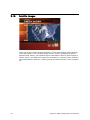
1
Viz Weather User’s Guide Product Version 2.1 November 27, 2013 Copyright © 2013 Vizrt. All rights reserved. No part of this software, documentation or publication may be reproduced, transcribed, stored in a retrieval system, translated into any language, computer language, or transmitted in any form or by any means, electronically, mechanically, magnetically, optically, chemically, photocopied, manually, or otherwise, without prior written permission from Vizrt. Vizrt specifically retains title to all Vizrt software. This software is supplied under a license agreement and may only be installed, used or copied in accordance to that agreement. Disclaimer Vizrt provides this publication “as is” without warranty of any kind, either expressed or implied. This publication may contain technical inaccuracies or typographical errors. While every precaution has been taken in the preparation of this document to ensure that it contains accurate and up-to-date information, the publisher and author assume no responsibility for errors or omissions. Nor is any liability assumed for damages resulting from the use of the information contained in this document. Vizrt’s policy is one of continual development, so the content of this document is periodically subject to be modified without notice. These changes will be incorporated in new editions of the publication. Vizrt may make improvements and/or changes in the product(s) and/or the program(s) described in this publication at any time. Vizrt may have patents or pending patent applications covering subject matters in this document. The furnishing of this document does not give you any license to these patents. Technical Support For technical support and the latest news of upgrades, documentation, and related products, visit the Vizrt web site at www.vizrt.com. Last Updated November 27, 2013 © Copyright Vizrt November 27, 2013 Contents 1 Introduction .............................................................................................. 1 1.1 1.1.1 Document Structure ........................................................................................... 1 1.1.2 Related Documents ............................................................................................ 1 1.1.3 Conventions ....................................................................................................... 2 1.2 2 2.1 New Features in Viz Weather 2 ...................................................................3 2.3 Workflow ....................................................................................................4 3.1 System Requirements .................................................................................6 3.1.1 Hardware Requirements ..................................................................................... 6 3.1.2 Software Requirements ...................................................................................... 7 3.1.3 Software Component Descriptions ..................................................................... 8 3.2 Installing Viz Weather .................................................................................8 3.4 Upgrading Viz Weather .............................................................................13 3.4.1 3.5 Installing the Database Schema ................................................................11 Folder Structure ............................................................................................... 14 Configuring Viz Weather ...........................................................................15 3.5.1 Command Line Options ................................................................................... 17 3.5.2 Viz Weather Setup Overview ............................................................................. 18 3.5.3 Network Configuration ..................................................................................... 20 Administrating the Points Database......................................................... 22 4.1 Points Configuration ................................................................................23 4.1.1 Point List Fields ................................................................................................ 25 4.1.2 Point Data Fields .............................................................................................. 26 4.1.3 4.2 Forecasts ......................................................................................................... 28 General Configuration ..............................................................................29 4.2.1 Regions ........................................................................................................... 29 4.2.2 Forecast Types ................................................................................................. 30 4.2.3 4.3 Conversions ..................................................................................................... 31 View .........................................................................................................31 4.3.1 Points List ........................................................................................................ 32 4.3.2 Points Data ...................................................................................................... 33 4.4 5 System Overview ........................................................................................3 Installation ................................................................................................ 6 3.3 4 Contact Vizrt ..............................................................................................2 Viz Weather............................................................................................... 3 2.2 3 About the Guide .........................................................................................1 Tools ........................................................................................................33 4.4.1 Export/Import .................................................................................................. 34 4.4.2 Database ......................................................................................................... 36 Meteorological Data Visualization............................................................ 37 5.1 Bands (IsoTherms) ....................................................................................37 5.3 Extremes (or H and L’s) ............................................................................38 5.2 5.4 Filled (IsoPrecip) .......................................................................................39 5.6 Fronts .....................................................................................................41 5.5 5.7 Lightning .................................................................................................41 Lines (IsoBars) ..........................................................................................42 5.10 Satellite Images ........................................................................................44 5.11 5.12 5.13 Radar Data ...............................................................................................42 Storm Tracking .........................................................................................45 Weather Point ...........................................................................................45 Weather Special Objects ...........................................................................48 Using Viz Weather ................................................................................... 49 6.1 User Interface Layout ................................................................................49 6.1.1 Meteorology Data Area .................................................................................... 49 6.1.2 Editing Area ..................................................................................................... 50 6.1.3 Animation Control Area ................................................................................... 50 6.1.4 Graphic Display Area ........................................................................................ 50 6.2 7 Flows .......................................................................................................40 5.8 5.9 6 Clouds Forecast ........................................................................................38 Main Menu ...............................................................................................50 6.2.1 File .................................................................................................................. 51 6.2.2 View ................................................................................................................ 51 6.2.3 Configuration .................................................................................................. 59 6.2.4 Viz ................................................................................................................... 80 6.2.5 Data Element ................................................................................................... 82 6.2.6 Playlist ............................................................................................................. 83 6.2.7 Weather Elements ............................................................................................ 84 6.2.8 Help ................................................................................................................. 86 Working with Meteorological Data ........................................................... 87 7.1 7.2 Points List ...............................................................................................87 Fetch ........................................................................................................90 7.2.1 Satellite Images ................................................................................................ 92 7.2.2 Model Data Forecast ........................................................................................ 94 7.2.3 Radar ............................................................................................................... 96 7.2.4 Misc Information .............................................................................................. 96 7.2.5 Clouds Forecast ............................................................................................... 96 7.2.6 Storm Path ....................................................................................................... 96 7.2.7 Lightning ......................................................................................................... 96 7.3 Points Data ...............................................................................................97 8 Working with Graphic Templates ............................................................. 98 9 Working with Playlists............................................................................ 101 9.1 Playlists ..................................................................................................102 9.1.1 9.2 Context Menu ........................................................................................................................ 103 Playlist Properties ...................................................................................105 9.2.1 General .......................................................................................................... 105 9.2.2 Layers ............................................................................................................ 109 9.3 Playlist Content Area ..............................................................................111 9.3.1 Context Menu ................................................................................................ 112 9.3.2 Columns ........................................................................................................ 119 9.4 Playlist Control .......................................................................................120 9.4.1 Initialization ................................................................................................... 120 9.4.2 Running a Playlist .......................................................................................... 122 10 Working with Data Elements .................................................................. 123 10.1 Concepts ................................................................................................123 10.3 Data Editors ...........................................................................................125 10.2 Saved Data Elements List ........................................................................124 10.3.1 Text Editor ..................................................................................................... 126 10.3.2 Weather Points Editor ..................................................................................... 128 10.3.3 Fronts Editor .................................................................................................. 129 10.3.4 Model Data Editor .......................................................................................... 132 10.3.5 Satellite Editor ............................................................................................... 134 10.3.6 Map Editor ..................................................................................................... 134 10.3.7 Pressures Editor (Extremes) ............................................................................ 137 10.3.8 Images Editor ................................................................................................. 139 10.3.9 Lightning Editor ............................................................................................. 141 10.3.10 Radar Editor .................................................................................................. 142 10.3.11 Objects Editor ................................................................................................ 142 10.3.12 Flows Editor ................................................................................................... 144 10.3.13 Clouds Editor ................................................................................................. 146 10.3.14 Winds Editor .................................................................................................. 147 10.3.15 Storm Path Editor ........................................................................................... 148 10.3.16 Hops Editor .................................................................................................... 149 10.3.17 Time Range Editor ......................................................................................... 151 10.3.18 Camera Selection Editor ................................................................................. 152 10.4 Debugging a Data Element .....................................................................152 11 Pre-production Mode ............................................................................ 154 12 Playout Mode ........................................................................................ 156 13 Fetch Application .................................................................................. 159 13.1 Main Menu .............................................................................................160 13.1.1 File ................................................................................................................ 160 13.1.2 View .............................................................................................................. 161 13.1.3 Tools ............................................................................................................. 162 13.2 13.2.1 Points Data (Live), Fetch and Points ........................................................163 Points Data .................................................................................................... 163 13.2.2 Fetch ............................................................................................................. 164 13.2.3 Points ............................................................................................................ 165 14 Appendix .............................................................................................. 166 14.1 Initialization Files ...................................................................................166 14.1.1 Viz Weather Initialization File ......................................................................... 167 14.1.2 Fetch Parameters Initialization File ................................................................. 173 14.2 Date File Format .....................................................................................174 14.3 Weather Data Suppliers ..........................................................................175 14.5 Using XML Formatted Data in Viz Weather ..............................................180 14.4 14.6 14.7 XML Conversion Tool ..............................................................................177 Working in Integrated Environments .......................................................182 Using Multiple Viz Weather Clients .........................................................184 14.7.1 Editing Playlists and Data Elements ................................................................ 185 14.7.2 Locked Playlist ............................................................................................... 185 14.8 Additional Columns ................................................................................186 15 Troubleshooting Guide.......................................................................... 187 15.1 Meteorological Data ...............................................................................187 15.1.1 General .......................................................................................................... 187 15.1.2 Storm ............................................................................................................. 188 15.1.3 15.2 ............................................................................................. Custom Weather 189 Viz Weather ............................................................................................190 15.3 Viz Engine ..............................................................................................192 15.5 .......................................................... DataBase Integrated Environment 193 15.4 Mixed Environment ................................................................................193 1 Introduction This is the user’s guide for Viz Weather version 2. 1.1 About the Guide This Viz Weather User’s Guide is designed to fit people with no or little experience in using Viz Weather. The purpose of this document is to help new users of Viz Weather become familiar with the system. 1.1.1 Document Structure Chapters 1 and 2 introduce the manual and Viz Weather. Chapter 3 describes the software requirements and installation procedures for Viz Weather and additional components. Chapter 4 describes how to administer the weather points database using the Viz Weather DBA tool. Chapter 5 describes a number of common meteorological data visualizations. Chapter 6, 7, 8, 9 and 10 all describe the Viz Weather client and all aspects of the user interface and how to operate it. Chapters 11 and 12 describe alternative modes of running Viz Weather that are tailored for pre-production and playout situations. Chapter 13 describes the Fetch application that is used for configuring and administrating the fetch options for the weather data. Chapter 14 gives more information on minute details such as parameters for configuring Viz Weather and weather data suppliers. Chapter 15 is a troubleshooting guide that covers the most common issues when operating a Viz Weather system. 1.1.2 Related Documents 1. Viz Artist User’s Guide - How to be creative in 3D space. 2. Viz Content Pilot User’s Guide- How to create and manage playlists, integrate to newsroom systems, setup a standalone VCP database and more. 3. Viz Curious Maps Client and Server User’s Guide - How to create maps-on-the fly and manage map servers. 4. Viz Engine Administrator’s Guide - How to setup and configure Viz Engine hardware and software. 5. Viz Template Wizard User’s Guide - How to create and organize templates. Chapter 1: Introduction 1 1.1.3 Conventions The following typographic conventions are used in this document: • Bold Text - Bold is used to indicate emphasized text. • Italic Text - Italic is used to indicate text that should be typed, or variables that should be entered. Italic is also used to refer to related documents. • Cross References - The color blue is used to indicate cross-references. • Numbered Paragraphs - Numbered paragraphs are used to indicate tasks that need to be carried out. Text in paragraphs without numbering represent ordinary information. 1.2 Contact Vizrt We encourage your suggestions and feedback regarding the products and this documentation. Our support e-mail address is [email protected]. You are also welcome to use the web-based support at www.vizrt.com, or to contact your local Vizrt support person by telephone. 2 Chapter 1: Introduction 2 Viz Weather Viz Weather is a complete 3D real-time weather solution. It features a broad range of advanced visualization possibilities in both HD and SD. Viz Weather integrates with a broad range of weather-data providers and can trigger graphics and animations automatically. An intuitive GUI allows to easily control, switch, and manipulate the data. The solution is fully integrated with Viz Curious Maps for creation of branded high-quality maps. This section contains information on the following topics: • New Features in Viz Weather 2 • System Overview • Workflow 2.1 New Features in Viz Weather 2 Viz Weather 2 has the following new major features: • • • • 2.2 New storage system for weather-point tables. Greatly enhanced scalability and flexibility. All types of weather graphics can be rendered on globes as well as flat maps. Support for telestration on globes and flat maps. System Overview This section contains information on the following topics: • • • • Integration of live weather data Advanced visualization and interaction Realistic weather presentation A template-based solution Integration of live weather data Viz Weather is a template based solution that allows the integration of live weather data into pre-defined graphic templates. Viz Weather supports weather information both from Vizrt’s partners and from local providers. Viz Weather supports local real-time weather data with a resolution of less than 1km, providing accurate local forecasts for use in transportation control and large outdoor sports events. Viz Weather includes an interface to Weather on Demand (WOD) services such as StormGeo and other providers. The combination of Viz Weather and WOD results in a flexible, online user-selectable weather feed for point forecasts, grid animation data, satellite data, observations and more. The area chosen for the forecast is covered by a global on-demand service, allowing the user to change the area of interest and the 3D animations within seconds. The WOD service allows to go on-air with locally updated weather information anywhere and Chapter 2: Viz Weather 3 anytime. This is particularly important in time-critical weather conditions such as floodings, hurricanes or wildfires. Advanced visualization and interaction Viz Weather allows users to change weather-data graphics in seconds. A separation between data and graphics representation allows meteorologists and weather presenters to edit and control the broadcast from a control system on the fly. Viz Weather graphics are designed using Vizrt’s 3D design application, Viz Artist. Its full range of design, animation and interactivity features is made available to the weather shows. Using these capabilities, weather shows can utilize touch driven presentations, sound effects and digital-video effects and even the integration of live video. Realistic weather presentation Viz Weather supports real-time weather presentation either through point-based symbols or as high-resolution 3D animations. The unique Particle Generator functionality allows the creation of a visually accurate representation of the forecasted weather development: The shape and movement of clouds can be visualized in 3D and broadcast showing the true speed of the various cloud layers. Weather data, such as temperature, wind speed and direction, weather symbols, 3D maps, and radar maps are displayed automatically with corresponding graphic elements in real-time, using the pre-made templates. A template-based solution Being fully based on templates results in an easy to use application and an efficient workflow. The predefined templates allow meteorologists, weather presenters and graphic designers to focus on weather conditions and present it in the best possible way without compromising the consistency with the channel’s branding. Viz Weather’s template-based approach combined with advanced playlist capabilities allows automated weather shows and the re-use of data for cross platform distribution: Viz Weather playlists can be turned into a set of images for mobile phones, web sites, etc. 2.3 Workflow When using Viz Weather to produce a weather show, the following steps are to be followed: 1. The graphic designer and the weather department create a storyboard of the show, which includes graphic guidelines and meteorological content to be presented. The graphic designer designs the graphic scenes (graphic templates) in Viz Artist. The designer must follow some guidelines and use special weather plug-ins when creating graphic templates for Viz Weather. The design process is done once and might be repeated every time a new look to the show is required. 4 Chapter 2: Viz Weather Note: For additional information about graphic template design, refer to the Viz Weather Scene Design Tutorial documentation. 2. When the design stage is done, the graphic templates are filled with data and saved as data elements. The data elements are then added to a playlist, to create the sequential structure of the weather show. This step is repeated every time the weather show editor wants to change the show’s flow. 3. The station’s meteorologist fetches the meteorological information and checks it. Manual correction of data and other fine-tuning is possible. This step is done daily. 4. The operator loads the Playlist to the Viz Engine before the show, and operates the Playlist controls during the show. Chapter 2: Viz Weather 5 3 Installation This chapter describes the installation procedure and how to configure the Viz Weather working environment. IMPORTANT! When installing or upgrading Viz Weather, please follow the latest documentation supplied with the installation files. If no special instructions are given, follow the instructions in this user guide. 3.1 System Requirements This section contains information on the following topics: • Hardware Requirements • Software Requirements • Software Component Descriptions 3.1.1 Hardware Requirements The following list is an extract of the current and most important hardware requirements needed in order to operate a Viz Weather system: • Control Machine • Design Machine • Render Machine Note: For a complete overview of hardware configuration options and requirements, contact your local Vizrt representative. Control Machine Viz Weather is used for controlling the graphics playout and for generating and previewing templates and data elements, but does not require video output. The Z400 is the typical control PC for Viz applications such as Viz Trio, Viz Content Pilot, Viz Weather and Viz Multichannel. • • • • HP Z400 (or newer) 3 GB Ram NVidia Quadro FX1800 768 MB Windows® XP Professional SP3 32bit When using complex scenes with a lot of textures you can replace the FX1800 with a FX3800 or FX4800 to get better performance. 6 Chapter 3: Installation Design Machine Viz Artist is used for design of graphic scenes, and does not require video output. Note that the HP Z400 can also be used as a Viz Engine without video inputs and codec support. • • • • HP Z400 (or newer) 3 GB Ram NVidia Quadro FX1800 768 MB Windows® XP Professional SP3 32bit When using complex scenes with a lot of textures you can replace the FX1800 with a FX3800 or FX4800 to get better performance. Render Machine Viz Engine is used for rendering the graphics, and does require video output. The HP Z800 is currently the default configuration for a HD/SD Viz Engine and Viz Artist: • • • • • • HP Z800 (or newer) 6 GB RAM NVidia Quadro FX4800 1.5 GB PCIe Windows® XP Professional SP3 32bit Matrox XMio2/24/6000 Matrox XMio2 Break-out Box Note: If the engine should be capable to play HD Video Clips use an XMio2/24/8500 instead of the XMio2/24/6000. See Also • Viz Artist manual • Viz Engine manual 3.1.2 Software Requirements The following software modules are used by Viz Weather: • Vizrt Software • Additional Software Vizrt Software • Viz Weather 2 • Viz Engine 2.8 PL5 HotFix 12 or later • DataPool plug-ins 2.11.4 • Extra Viz plug-ins 1.19.X.X • Viz Engine 3.2.2 or later • DataPool plug-ins 2.11.4 • Media Sequencer 1.19.X Chapter 3: Installation 7 • Viz Curious Maps Client 10.0.0 or later Additional Software • • • • 3.1.3 Python 2.6.2 DivX (or any other codec for rendering video clips) Oracle 10.2 Server (for managing points, one server in the system) Oracle 10.2 Client (on Viz Weather2 client machines) Software Component Descriptions The following is a list of additional software components needed in order to ensure Viz Weather is operating properly: • Viz Engine: The graphic render software by Vizrt. The graphic engine renders 3D graphic models with the meteorological data. • Media Sequencer: Vizrt timing and control mechanism. Viz Weather loads an XML file, containing all the data of the GUI, to the Media Sequencer. • Viz DataPool: Viz Engine plug-ins for manipulating Data. These plug-ins are added to Viz Engine during DataPool installation. • Viz World Client- A group of plug-ins and a client ActiveX used to retrieve maps from a network Viz World Server. The plug-ins are required for running geographical oriented graphics (even if not using the Viz World Client/Server option). • Extra Viz Plug-ins: Viz Engine plug-ins enabling communication and data transfer between UI applications (Viz Trio, Viz Weather, Viz Content Pilot, etc.) and Viz Engine. These plug-ins are added to Viz Engine during the installation. • Python: Viz Weather data fetching mechanism uses python scripts for downloading data from the data suppliers. Python has to be installed or the scripts will not work. • Oracle Client: An oracle client, version 10.2 or higher, should be installed on all Viz Weather machines. The Oracle client enables Viz Weather to connect to the Oracle server, where the weather point data is stored. • Oracle Server: One Oracle server should be installed in the system. The Oracle server stores all weather points data. 3.2 Installing Viz Weather • Download the entire version folder locally (maintaining the folders hierarchy) from Vizrt’s FTP site. • Install the recommended Viz version supplied in the top folder. Note: All plug-ins and Viz Engine dll’s are installed to Viz installation folders. Viz Weather installer will automatically detect the path of the latest installed Viz and use it to install the required files. A general installer for Viz Weather is used to automatically launch all the required software packages sequentially. Follow the instructions of each installer until all installers are completed. If a restart message is displayed during any of the installations, select “restart later” and continue to install the packages. When all 8 Chapter 3: Installation software packages are installed, restart your machine. The general installer and the Viz Weather software installation packages are found on Vizrt’s FTP site. Note: Oracle software modules (Oracle 10.2 client or server) are installed separately. Oracle server installation and Oracle client configuration should be performed by a qualified systems administrator. To install Viz Weather Figure 1: Selecting the type of installation type CAUTION! Previously installed software (e.g. Media Sequencer) must be uninstalled before running the Viz Weather all installer and its components. 1. Run the VizrtVizWeather2All.X.XX.X.exe installation file. 2. Select the machine type to install and click Next. • Control Machine: Installs all software packages required to run the Viz Weather user interface: edit, prepare and run weather shows, control Viz Engine machines, etc. • Custom: Allows you to manually select software components to be installed. • Engine Machine: Installs all Viz Engine related packages, required for loading and displaying Viz Weather graphics (no user interface). • Server Machine: Installs all the required software packages to run a Viz Weather server, i.e. fetch new meteorological data, allow Viz Weather clients to connect to the local Media Sequencer, and so on. 3. In the list of the software packages, add or remove software components to customize the installation, or click Next to keep the default selection. Chapter 3: Installation 9 • Default selection is based upon the installation type selected in the previous screen. Figure 2: Viz Weather page installer, installation list. 4. Follow the instructions in each of the individual installers. • If a machine restart message is displayed, continue with the installation without restarting the machine until all the installers are finished. • The selected software installers will run sequentially, in the correct order, until the installation is completed. 5. Launch Viz Weather’s database creation wizard (WD_Wizard). • WD_Wizard can be found in %SystemDrive%\Program Files\vizrt\vizWeather2\WD_Wizard 6. If you are connecting to the database for the first time, configure the database connection. 7. Follow the instructions in the WD_Wizard pages to generate the weather points table space, user and tables. 8. Restart the machine. To manually install the control machine’s software packages 1. Make sure Viz Engine or Viz Artist is installed. 2. Install the data pool plug-ins (DataPool_<version>.exe). 3. Install the extra Viz plug-ins (ExtraViz#Plugins-<version>.exe) for the Viz version you are running (either Viz 2 or 3). Note: Extra Viz plug-ins are not needed for Viz 3.3 and later. 10 Chapter 3: Installation 4. Optional: Copy the Viz Weather demo archives to a local folder, run Viz and import the archives. 5. Install the Viz World Maps Client. 6. Install and start the Media Sequencer. 7. Install Python. 8. Install Viz Weather (not the All installer). • The installer will check for viz versions installed on the machine (Viz 2.X, Viz 3.X). 9. Select a Typical installation. • If run for the first time on the machine, the installer will launch Viz Weather’s database creation wizard (WD_Wizard) after Viz Weather has been installed. 10. Copy the replaced plug-ins from the installation folder to Viz’s plugin folder. • Replaced plug-ins can be found in ...\VizWeather<version>\Installers\ReplacedPlugins\ Note: Files with file extension .evp are Viz 2 plug-ins, while .vip are Viz 3 plug-ins. 11. Open the installation folder and edit the initialization files for Viz Weather and Fetch Parameters. See Also • Installing the Database Schema • Initialization Files • Viz Weather Initialization File • Fetch Parameters Initialization File 3.3 Installing the Database Schema Before any installation or upgrade of Viz Weather specific schemas, an Oracle 10g database must be installed and running, and Viz Weather must be installed. Viz Weather makes use of the database for storing weather points and all the points related data. The schema for storing the points uses a version number to check for compatibility and allow schema changes and updates. Note that Viz Weather will not run if there is a schema mismatch. If a mismatch occurs a message will be displayed. Once the schema has been updated to the correct version, Viz Weather can be used again. To install and configure the weather points schema 1. Run the Viz Weather 2 installer. • If the Viz Weather 2 installer is run for the first time on the machine, the WD_Admin tool will be automatically launched at the end of the installation process. • Another option is to run the WD_Wizard manually from the %SystemDrive%\Program Files\vizrt\VizWeather2\WD_Admin folder. Chapter 3: Installation 11 2. Select TNS or Basic (connection string) and set the database connection parameters, and click Next. • If the connection to the database succeeded, Viz Weather configuration settings will be displayed. 3. Click Next to create the WHEATER tablespaces. 4. Select Create clean tables (default) and click Next. 5. Optional: Select Create from Dump file if you have a dump file from an existing database. For additional details, contact your systems administrator. 6. Optional: Save the database preferences to a Viz Weather Initialization File. 12 Chapter 3: Installation 7. When the process is finished, close the application. Note: Creating a shortcut to WD_Wizard and running it with the "-custom" flag in the target path will enable you to skip stages and configure default parameters during the installation. 3.4 Upgrading Viz Weather Viz Weather upgrades are installed using the Viz Weather installer. The Viz Weather installer utilizes one installer for Viz Weather running on Viz 2.x and Viz 3.x. The installer will automatically determine which Viz version was installed last and install the required files. To upgrade Viz Weather 1. Run the installer and select one of the following options: • Upgrade and keep user configuration: Upgrades Viz Weather software and keeps existing configuration files. • Upgrade and re-install configuration: Upgrade Viz Weather software, creates a backup of existing configuration files and installs new default configuration files. • Change installed components: Displays a list of Viz Weather components currently installed that allows you to change (select/deselect) installed components. • Uninstall Viz Weather: Removes Viz Weather software (configuration files are not removed during an uninstall). Chapter 3: Installation 13 2. Optional: Upgrade other software packages included in the Installers folder for the upgraded version of Viz Weather. See Also • Installing Viz Weather 3.4.1 Folder Structure Viz Weather files and folders are installed under the default path (%SystemDrive%\Program Files\vizrt\vizWeather2) or under a custom path set by the user during the installation. The application files (.exe) and configuration files (.ini) are also installed under this folder. The installation folder contains the following sub folders: • Backup\XML: a folder containing backup XML files. The files are copied by Viz Weather during startup. Note: If Viz Weather is unable to launch, copy the last backup XML to the xml folder, rename it and try running Viz Weather again. • DataSuppliersDlls: a folder containing the fetch dll's. These dll's manage the download of meteorological data. • Docs: Viz Weather documents are copied to this folder during installation. • Fetch_scripts: Python scripts for downloading grid data and creating IsoBars, IsoPrecip and IsoTherms data files. • Sat-calibration-images: The folder contains sample sat images from different satellites. The images have a bold mark along the coastline to help calibrate the satellite images to maps. These sample images are geo referenced and can be used when a non geotiff map is used. Placing the referenced image on top of the non referenced map will emulate geographic referencing when used by Viz Weather to place Wpoints. • SceneIcons: Icons of the saved data-elements are saved in this folder. • SimpleCityData: Text files containing geographic data of cities (longitude/ latitude values of cities). The files are accessed from Viz Weather UI when selecting the add points from database option. • Symbols: sample symbols for weather conditions (rainy, cloudy, etc.). • vizrtDef: This folder contains structured information used by the Viz Weather application. • WD_Wizard: this folder contains the database wizard application. The application is launched after Viz Weather is installed for the first time, or it can be launched manually by the user. The wizard is used to create a table space in the database and define the required database element for hosting weather points in the system. • xml: A folder containing XML file/s with all the saved information of the Viz Weather GUI. This file is loaded by the media sequencer when Viz Weather launches. The name of the loaded file is defined in the viz_weather.ini file. • XMLConfigFiles: UI configuration files. These files contain user settings configured by the Configuration menu items. 14 Chapter 3: Installation 3.5 Configuring Viz Weather Viz Weather is not a standalone product; hence, it must be configured to work with other Vizrt products such as the Media Sequencer and Viz Engine before it can be started. When installing Viz Weather, desktop shortcuts for running Viz Weather with Viz 3.x and Viz 2.x will be created. Plug-ins and configuration files for the installed Viz version will be installed. Viz Weather connects to the Media Sequencer service as a server machine or as a client machine depending on the Command Line Options configuration. This section contains information on the following topics: • • • • • To To To To To configure configure configure configure configure Viz Viz Viz Viz Viz Weather Weather Weather Weather 3.x to to to to run as a client run as a server use Viz 3.x use Viz Worlds Maps Client To configure Viz Weather to run as a client 1. Right-click the Viz Weather2(Vizx.x) shortcut, and from the appearing context menu select Properties. 2. Select the Shortcut tab, and add the following command line option to the target path: -weatherclient –MSE <machine_name>. 3. Click OK. To configure Viz Weather to run as a server 1. Right-click the Viz Weather2(Vizx.x) shortcut, and from the appearing context menu select Properties. 2. Select the Shortcut tab, and add the following command line option to the target path: –MSE <machine_name>. Note: When running a Viz Weather sever with the local Media Sequencer, these flags are omitted. 3. Click OK. To configure Viz Weather to use Viz 3.x 1. Open the Viz Weather Initialization File for Viz 3.x located in the Viz Weather program folder %SystemDrive%\Program Files\vizrt\VizWeather2\viz3_weather.ini. 2. Locate the VIZ category and set the Viz version parameter. [VIZ] viz_version=3 3. Save and close the INI file. Chapter 3: Installation 15 4. Right-click the Viz Weather2(Viz3.x) shortcut, and from the appearing context menu select Properties. 5. Select the Shortcut tab, and add the following command line option to the target path: –inifile viz3_weather.ini. 6. Click OK. To configure Viz Weather to use Viz Worlds Maps Client 1. Open the Viz Weather Initialization File for Viz 3.x located in the Viz Weather program folder %SystemDrive%\Program Files\vizrt\VizWeather2\viz3_weather.ini. 2. Locate the CURIOUS category and enable the Viz Curious Maps Client (CMC). [CURIOUS] cwm_enabled=y 3. Save and close the INI file. To configure Viz 3.x 1. Start Viz Config 3.x 2. Select the Database category and enable Auto Login (Yes). 16 Chapter 3: Installation 3. Optional: Select the Viz Artist 2.x section to enable Use 2.x Mode for demo scenes and materials. 4. Select the Maps category and configure the Viz World map database settings. 5. Set the Cache Directory to a shared folder between the control machine (Viz Weather) and the output machine (Viz Engine). 6. Click Save and close Viz Config. See Also • Viz Weather Setup Overview • Viz World Client and Server User’s Guide 3.5.1 Command Line Options Viz Weather can make use of command line options (flags) that will enable you to use various shortcut configurations. The flags are added to the shortcut’s target path or used when running Viz Weather from a command shell. Note: All command line options will override the configuration made in the Viz Weather Initialization File. • -mse <hostname>: Sets the name of the computer running the Media Sequencer. Default value is localhost (*). The following flags define the connection type used by Viz Weather to connect to the Media Sequencer. Use only one of the flags. • -socket: Connects to the Media Sequencer using socket Protocol (ctSocket). This is the default value if no connection type is defined (*). • -dcom: Connects to the Media Sequencer using CacheDCOM Protocol (ctCacheDCOM). This is the type of connection used in previous versions (*). • -usecache: Connects to the Media Sequencer using CacheDCOM Protocol (ctCacheDCOM). This is the type of connection used in previous versions (*). • -nocache: Connects to the Media Sequencer using DCOM Protocol (ctDCOM) (*). • -weather_machine <machine name>: Defines the On-air machine Viz Weather will connect to. • -nogui: Launches Viz Weather without the GUI. This option is used in integrated newsroom systems environments. Chapter 3: Installation 17 • -showlog: Used with conjunction with nogui flag. The showlog flag will open a Viz Weather log window when running without the GUI. • -xml_file <xml file name>: Defines the weather xml file name that will be loaded to the Media Sequencer when Viz Weather is launched as server or stand alone machine (*). • -lang <language name>: Defines the UI language that Viz Weather will load. Default language is English. Language name is the name of a sub directory containing the language definition file for Viz|Weather.(*) • -hd: Run Viz Weather with the render window displaying HD format, i.e. 720X406, and using the Viz Engine's EDITOR command format instead of the RENDERER (*). • -weatherclient: Connects to the Media Sequencer server as a client. Editor and UI functions are the same but a data locking and priority mechanism is used to avoid simultaneous data saving. • -playout: Runs Viz Weather in playout mode, i.e. no data elements editing capabilities are enabled. This mode is used in control rooms where the object of the application is to control and play Viz Weather playlists. To use this feature a specific license is required. • -editors: Runs Viz Weather in Pre-production Mode. This mode is used for editing data elements only. No playlist or configuration options are enabled. This mode requires a Viz Weather plug-ins license (not a full Viz Weather license). • -configfiles <files_path>: Runs Viz Weather using the configuration files found the specified path. The path should contain the configuration files in the same folder structure used in the Viz Weather installation folder. Missing files will be loaded from the Viz Weather folder (*). • -inifile <file_name>: Runs Viz Weather using the specified ini file. If the file is not valid Viz Weather will not load (*). • -gateway: Runs Viz Weather in as a gateway manager. The gateway manager assigns data elements to the gateway queue and sends the items to the client gateway machines for rendering (*). Note: Flags marked with an asterisk (*) are used by the fetch_viz_weather application as well. See Also • Viz Weather Initialization File • Pre-production Mode 3.5.2 Viz Weather Setup Overview When Viz Weather is launched it will run Viz Engine and connect to the Media Sequencer service as a server machine or a client machine depending on the Command Line Options setting. Viz Weather’s XML file is loaded to the Media Sequencer by the Viz Weather server instance and used by all Viz Weather clients connected to the same server. The Viz Weather user interface controls the graphics through a set of commands sent to Viz Engine, adding the defined meteorological data to the basic scenes (graphic templates). 18 Chapter 3: Installation Note: The Viz Weather XML files is located in the following directory; %SystemDrive%\Program Files\vizrt\VizWeather2\<version>\xml This section contains information on the following topics: • Standalone Machine • On-air and Control Machines Standalone Machine A Standalone machine is a single PC/machine with a video card, running both the Viz Weather UI and the Viz Engine renderer, producing an SD or HD video output signal. On-air and Control Machines The On-air and Control machines are two machines connected via network. The Control machine runs the UI and sends commands and data to the On-air machine. All editing and data manipulation is done on this machine. The control machine is running Viz Engine for editing, and can be used as a preview machine during production - showing the next item in the Playlist. The On-air machine is either a PC or Onyx that runs Viz Engine and that produces an SDI or HD video signal. The On-air machine is controlled by the control machine during production - sending commands and weather data to create the weather show. In the Viz Weather Initialization File, configure the on_air_machine parameter to indicate the On-air machine being used, and the on_air_preview_disable parameter. Chapter 3: Installation 19 Note: When using a program (PGM)/ preview (PVW) configuration some additional Network Configurations must be made. See Also • Network Configuration 3.5.3 Network Configuration When using an On-air/Control configuration, or in an environment with a few Viz Engine installations, all machines should all be connected to the same Viz Graphics Hub for Viz 3.x or data root for Viz 2.x versions. A shared fetch folder and image folders should also be mapped on all machines. Note: The Viz Graphic Hub database and the Viz 2.x data root directory is configured in the Viz Config tool. 20 Chapter 3: Installation To define the path of the Fetch folder and the Images database folder 1. Start Viz Weather. 2. From the main menu select Configuration, and from the appearing menu select System Configuration. 3. Enter the password (default is admin) in the appearing password confirmation dialog box, and click OK. 4. Open Windows Explorer on the Viz Engine program (PGM) machine, and create a shared folder, and under that folder create the FetchData and IMAGES_DB folders. 5. Map the share folder, using the same drive letter, on all control and render machines. 6. In the System Configuration window select the Fetch tab and set the destination folders for the fetch and image data. 7. When done, click OK. Note: Viz Weather sends the path of the images and the fetch data to both Viz Engine preview and program machines during the initialization process - if one machine does not have the correct path, the images/data will not be visible. Chapter 3: Installation 21 4 Administrating the Points Database The Viz Weather Database Administration (DBA) tool is used to configure the structure of the points data tables, the additional data fields and the relation between the data fields and the DataPool variables. The configuration categories on the left are used for selecting the required parameters. When a category is selected, the pane on the right will display the available properties and parameters. This section contains information on the following topics: • • • • Points Configuration General Configuration View Tools To open the Points database administration tool 1. Open the Viz Weather program folder %SystemDrive%\Program Files\vizrt\VizWeather2 2. Run the program Viz Weather Database Administration tool (WD_Admin.exe) 22 Chapter 4: Administrating the Points Database Note: When the database is empty, the system will prompt about defining a point type, as this is an essential component of the system. 4.1 Points Configuration The Point Configuration category consists of three main options, and a point type selection for each of the main options. The Point Type displays a list of defined point types in the system. If any of the options from the Points Configuration category is selected, the Point Type drop down list and edit button will be displayed at the top part of the pane on the right at all time. This section contains information on the following topics: • Point List Fields • Point Data Fields • Forecasts To edit a point type 1. Click the Edit button next to the Point Type list to open the Point Type editor. 2. Select a point type and click Remove to delete the point type from the system. 3. Select a point type and click the Modify button, to change an existing point type parameter. 4. Click the Add button to open the Point Type Details Editor. Chapter 4: Administrating the Points Database 23 5. Enter a point type name (or modify the existing name) to create a new point type. • The DataPool name field will be populated with the same name defined in the Point Type Name field. Modify the DataPool name if required. • DataPool Name: Defines a DataPool structure name to be used by Viz Weather when sending the point data to Viz. Note that on any point’s fields change, a new config.dp file has to be exported and copied into the Viz folder. When using a DataTable or a flat DataObjects list, the DataPool name will be the prefix of the data structure. Note: If a change was made to the point’s fields, a popup message, prompting the user to export the config.dp file, will appear when exiting the WD_Admin. 6. Select whether or not to enable automatic field lock. • Enable Automatic Field Lock: When checked, any manual change to a point data field in Viz Weather will automatically lock the changed field. Locked fields will not be updated by a fetch operation until the lock is manually released or the lock expires according to the expiration time set for the point type. 7. Select one of the options to set an automatic lock expiration. • Lock Expiration Kind: No Expiration - data fields lock will not expire (only manually). On System Day Switch - all data fields lock will expire when the system date changes. On Specific Time - all data fields lock will expire when the system clock reaches the specified time. • Last Unlock Was At: Displays the time and date that the last automatic unlock occurred. 8. Select the type of default fields that should be defined for the new point type. • Add Default Fields: Point fields define the point attributes (long, lat, etc.) and Point Data fields define the data values that will be available for the each point. 9. Click OK to add the new point type to the list. 24 Chapter 4: Administrating the Points Database 4.1.1 Point List Fields The Point List Fields option defines the fields associated with the point properties, i.e. Longitude, Latitude, Height, etc., of the selected Point Type. When creating a point type, a default set of fields will be created (optional). Selecting a point type from the Point Type drop list will populate the defined point fields. The list of fields can be modified by adding, removing or editing any of the fields. Note: The default fields are a set of basic properties of a weather point. When trying to delete one of the default point fields, a warning message will appear. The Point Categories editor defines a list of available categories for the selected Point Type. These categories can be used later to categorize points of the selected Point Type and enhance the filtering and organizing abilities of Viz Weather points. Note: The specified Categories will be available for the selected point type only. When using more than one point type, define the categories for each point type. Chapter 4: Administrating the Points Database 25 4.1.2 Point Data Fields The Points Data Fields option is used for defining data fields for the points in the selected point type. A set of default data columns are pre-defined when creating a new Point Type that allows the default fields to be created. These fields are used in the data structure sent to Viz. This option is used To configure additional data columns and customize the point data fields according to the supplied data and the graphics. To configure additional data columns and customize the point data fields 1. In the Points Data Fields pane, click the Add button to open the Forecast Field editor. 2. Set the Field name and the Display name. • The field name will become the column name in the database, the Display Name is the name used in the UI when using the data table view. 3. Set the field type, text, integer or float. 4. Set the control type that will be used in the UI for displaying the data field. • Field Type: If Field Type was set to Float, set the round value of the data (the number of digits after the decimal point). • Default Width: Sets the default width of the column in Viz Weather UI. 5. Set the DataPool Name, i.e. the data field name that will be used in the config.dp file, and will be sent to Viz by Viz Weather. 6. Set the source for the Control Type. 26 Chapter 4: Administrating the Points Database 7. Set a conversion rule for incoming data by selecting a pre-defined conversion from the list, or click the ellipse (...) button next to the conversions list to add a new conversion rule. 8. Optional: Click the Add button to create a new conversion formula. • Modify and Remove: Modifies or deletes the conversion parameters. • The conversion Formula is of the following format: Data Value = (Incoming data * Param A)+ Param B 9. Set the XML tag to be used. • XML tag: If using a tag, set the tag name. If using an attribute, set *.attribute Name. 10. Set the XML file to the # (hash) sign or set an XML file name. • # sign: Will use the main xml defined in the fetchparameters.ini priority. • File: Use this option if using a local xml file only. 11. Click OK. Chapter 4: Administrating the Points Database 27 4.1.3 Forecasts The Forecasts option is used for defining time values for which the fetched data will apply. A weather point is represented by a location and the data for a specific time. Forecast times are defined per point type. Select a point type from the list and set the required forecasts. Before setting a forecast, set the Forecast Type in the system. Forecast types are defined per system and used in all the defined forecasts. When creating Viz Weather table space and tables, two default forecast types are defined: Obs (stands for Observation) and Forecast. To define a forecast type 1. 2. 3. 4. In the Forecasts pane click the Add button to open the Forecast editor. Set the forecast name. Select the forecast type (Obs (observation) or Forecast). Set the day offset to the correct offset (where zero is today) and the time of forecast or observation. IMPORTANT! When using Obs, always set the Day Offset to -1. 5. Set a description of the forecast. • This field is only used by the Viz Weather Database Administration tool (WD_Admin.exe). 28 Chapter 4: Administrating the Points Database 6. Check the Default Forecast check box if this forecast should be the default forecast displayed when using the points data view. 7. Click OK to add the forecast. 8. Back in the Forecasts pane, select the Forecast Fields to be used for the new forecast type. • All checked fields will be displayed in the UI when selecting the forecast time. 4.2 General Configuration The General Configuration category is used to configure global system values. This section contains information on the following topics: • Regions • Forecast Types • Conversions 4.2.1 Regions The Regions option is used to define a list of countries, regions and sub-regions in the system. This list will be available in all point types. The regions in the system are used for filtering the points list display when creating data elements in Viz Weather. Chapter 4: Administrating the Points Database 29 The Add, Modify and Remove buttons can be used to add new, modify and remove entries in the selected columns. There is an hierarchy in the system where country is defined first, then a region in this country, and then a sub region for the selected region. 4.2.2 Forecast Types The Forecast Types option defines global forecast types (Obs, Forecast etc.) used in the Forecasts tab to define the Forecast times of data. The Add, Modify and Remove buttons can be used to add new, modify and remove entries. To add a new forecast type 1. Click the Add button. 2. Set the forecast type name. 3. Set the expiration time in seconds. • This parameter defines the minimal time gap between two fetch actions that the points of the selected point type will be updated. That is if a point was fetched, it will not be fetched again until the expiration time value has past. 4. Click OK. 30 Chapter 4: Administrating the Points Database 4.2.3 Conversions The conversion option is used to define conversion formulas for converting incoming data. All conversions are of the following format: Field Data = (Incoming data value * A) + B The Add, Modify and Remove buttons can be used to add new, modify and remove entries. To add a conversion formula 1. 2. 3. 4. 5. 4.3 Click the Add button to add a conversion formula. Set the conversion name. Set the first parameter (A) Set the second parameter (B) Click OK. View This section contains information on the following topics: • Points List • Points Data Chapter 4: Administrating the Points Database 31 4.3.1 Points List The Points List option displays a list of geographic locations (weather points). This tab is used for defining points in the system manually, and to test the fetch configuration. The lower bar in the Points List pane is used to fetch data for the defined points/ forecast times. This section also contains information on the following topics: • To add a new point • To update forecast data for the selected point(s) To add a new point 1. Right click the points pane, and from the appearing context menu select New Point (Ins). • This will open the Search Point window. 2. Select either the Yahoo (Web) or Local Database option for your search. 3. Search or look up the city you want to add to the Points List. 4. Click OK. To update forecast data for the selected point(s) 1. Select one or several points from the Points List. 32 Chapter 4: Administrating the Points Database 2. Select the required options in the drop down combo boxes at the bottom of the Points List pane. 3. Click Fetch. 4.3.2 Points Data The Points Data pane displays the defined points and the available data fields for each forecast time. When performing a fetch for all points the table is filled with the available data. Required point types and the specific forecasts can be selected from the drop down combo boxes at the top left side of the pane. Note: The table columns are the selected additional fields defined for each forecast and point type. 4.4 Tools This section contains information on the following topics: • Export/Import • Database Chapter 4: Administrating the Points Database 33 4.4.1 Export/Import The Export/Import tab enables the user to add data to the system from external files and to export information to be used by Viz and Viz Weather. • Import Points: When clicked, a file browser will open that will allow you to browse and select a valid Viz Weather XML file. By selecting a point type from the list displayed the weather points from the Viz Weather XML file will be imported to the selected Points Type. • Import Forecast Types: When clicked, a file browser will open that will allow you to browse and select a valid forecast type XML file. The forecast types from the XML file will be imported to the database. • Import CSV: This option enables you to import points from a comma separated file. When clicked, a file browser will open that will allow you to select the CSV file to import. SEARCHID,name ID1,Name1 ID2,Name2 IMPORTANT! The column headers of the file must use the same name as defined in the system and should also be comma separated. • Export Config.dp: When clicked, a file browser will open that will allow you to browse to the Viz folder in use. A DataPool configuration file will be created, at the designated path containing all the point type fields structure. • The exported file should be copied (or exported again) to all Viz Engine machines used by Viz Weather. 34 Chapter 4: Administrating the Points Database • The file structure represents the additional columns and point types in the database as DataPool fields structure. The data from vIz Weather will be sent to VIz in the same format. • Export Database: When clicked, a file browser will open for selecting a target folder. When selected, a database snapshot will be created (all the database structure and data will be exported). IMPORTANT! The export option uses the Oracle EXP command. This option will only work on the server or by using an Oracle 10g Administrator client. • Export Points Dictionary: Points dictionary is a file containing an index of the weather points names and database ids. • The database point ID is a unique number (key) representing the point in the database. • A dictionary file is created for every Point Type in the system, using the following naming convention: Dictionary_<point type name>.xml. • When the data is sent to Viz, the ID string is the identifier used to set the data objects in the scene. • The export dictionary button will export all points in and all forecasts in the format of an XML file. Example XML of an exported dictionary: <PointTypes> <PointType> <ID>5</ID> <Name>Forecast</Name> <Points> <Point> <ID>289</ID> <Name>Fairbanks</Name> <State>AK</State> </Point> <Point> <ID>290</ID> <Name>Huntsville</Name> <State>AL</State> </Point> </Points> <Forecasts> <Forecast> <ID>9</ID> <Name>Today</Name> </Forecast> </Forecasts> </PointType> </PointTypes> Chapter 4: Administrating the Points Database 35 4.4.2 Database The database option is used for configuring the database connection string, and consequently connect the Viz Weather Database Administration (DBA) tool to the Oracle database. • Connection String: This connection string is defined set in Viz Weather Initialization File, under the [WD_SERVER] section. The connection string includes a set of values required to connect to the database: • Provider: Database application type and ODBC used for connection. • User ID: Username for the connection. • Password: Password for the defined user name. • Data Source: Name of the database instance (machine name\instance name). To change the connection string 1. Click the ellipse (...) button next to the Connection string field to open the Microsoft ODBC configuration tool. 2. Select and set the required configuration options and parameters and test the connection. 3. Close the ODBC tool. 4. Click the Save configuration button to save the Viz Weather DBA tool to save the changes to the Viz Weather Initialization File. • If the configuration changes are not saved, a dialog box asking for changes to be saved will appear when the Viz Weather DBA tool is closed. 36 Chapter 4: Administrating the Points Database 5 Meteorological Data Visualization This section describes some of the options to visualize meteorological data in Viz Weather. Most of the examples are taken from Viz Weather graphic design tutorial and from demo scenes. This section contains information on the following topics: • • • • • • • • • • • • • 5.1 Bands (IsoTherms) Clouds Forecast Extremes (or H and L’s) Filled (IsoPrecip) Flows Fronts Lightning Lines (IsoBars) Radar Data Satellite Images Storm Tracking Weather Point Weather Special Objects Bands (IsoTherms) Bands are used to graphically describe temperature levels (IsoTherms) and other types of data as segments of color or texture. The forecast is supplied for a requested time period, at fixed intervals, and the bands are drawn for each interval and played sequentially, creating an animation of the colored segments. Chapter 5: Meteorological Data Visualization 37 5.2 Clouds Forecast Clouds forecast data are a set of B&W images. The images are used in a graphic template to create a 3D graphic representation of clouds, using particles. 5.3 Extremes (or H and L’s) H and L represent High and Low pressure areas. Extremes will be used over an air pressure levels map and indicate the high and low pressure areas. Note: Extremes can be added automatically from the IsoGrid plug-in. 38 Chapter 5: Meteorological Data Visualization 5.4 Filled (IsoPrecip) Color or texture filled areas are used to graphically describe precipitation levels (IsoPrecip) and other types of data. The forecast is supplied for a requested time period, at fixed intervals, and the filled areas are drawn for each interval and played sequentially, creating an animation of the filled areas. Another option is to display precipitation levels by using particles: A combination of data can be used in a graphic template (up to seven data types in one graphic template, depending on performance issues). Chapter 5: Meteorological Data Visualization 39 The above example combines pressure data and precipitation data in the same graphic template. 5.5 Flows Flows are objects used for displaying animated movement of meteorological phenomena. Flows are commonly used to display winds or water currents. 40 Chapter 5: Meteorological Data Visualization 5.6 Fronts A meteorological front is defined as the transition zone between two air masses of different density. In Viz Weather, a Front is the graphical representation of a meteorological front. 5.7 Lightning Lightning information describes lightning occurrences over a map. Chapter 5: Meteorological Data Visualization 41 5.8 Lines (IsoBars) Lines are used to graphically describe pressure levels (Isobars) and other types of data as curved lines (similar to a topographic map). The forecast is supplied for a requested time period, at fixed intervals. The lines are drawn for each interval and played sequentially, creating an animation of the lines. Labels and extreme values can be added automatically to the animated lines. 5.9 Radar Data Observed precipitation quantities are often displayed as a sequence of images taken by radar. The images describe precipitation as colored dots on a black background (with Alpha). The color of the dots indicates the type/amount of precipitation in that area. The above example shows a radar frame over a map. 42 Chapter 5: Meteorological Data Visualization The example below shows the same information, in another graphic template, converted to particles, showing clouds and rain. ISO information is used for displaying a forecast while radar and satellite images are used for displaying observed data. Since the time range of the information displayed is set in the Viz Weather UI, It is advised not to use ISO information with radar/satellite information. Using both in the same scene will produce time range warnings when loading the graphic-template/data-element to the UI. See Also • Viz Weather tutorial for more information on using radar and satellite images in a scene. Chapter 5: Meteorological Data Visualization 43 5.10 Satellite Images There are several meteorological satellites in orbit around Earth, taking pictures of the atmosphere. The received images show a specific geographical area at different time stamps. The meteorological information shown in these images is clouds, storms, etc. When the images are displayed as a sequence they show the observed weather conditions, showing clouds movement (winds), storm progress etc. 44 Chapter 5: Meteorological Data Visualization 5.11 Storm Tracking The above examples show options for displaying storm paths (both observed and forecast paths). 5.12 Weather Point A weather point is an object containing text objects, images and 3D objects, displaying meteorological data about a specific geographical place (point) at a specific time. Designs vary according to the information displayed. Weather points can be used over a map with geographical referencing, in a table or as graph points. This following sections contain examples on typical weather point designs: • • • • Weather Points Table Weather Points over a Flat Map with Geographical Referencing Points over a Globe Weekly Forecast Graph Chapter 5: Meteorological Data Visualization 45 Weather Points Table A weather point table displays a number of points without geographic referencing. The displayed data shows a number of forecast times referring to the same weather point or a number of weather points referring to one forecast time. The above example shows a temperature forecast for a European capital. Weather Points over a Flat Map with Geographical Referencing Display any point related information over a map, where the point is place at its geographical location on the map. The above weather point design includes the point’s name, temperature, weather conditions icon and a pointer (orange dot) on the map, indicating the city location. 46 Chapter 5: Meteorological Data Visualization The above scene example displays the weather point’s name, temperature, wind direction indicator and a weather vane for showing wind speed. Points over a Globe Display any point related information over a Globe, where the point is placed at its geographical location. Weekly Forecast Graph The graph display type is similar to the points table display, with the addition of using a graph to display data variation. The temperature values are used to control the graph points. Chapter 5: Meteorological Data Visualization 47 The above weather point design shows the temperature, weather conditions symbol and date.This graphic template also uses the MinMax feature, which normalizes the graph according to the temperature's minimal and maximal values. 5.13 Weather Special Objects Weather related phenomena, such as sand storms, blizzards, fire, etc., are shown in the example above. 48 Chapter 5: Meteorological Data Visualization 6 Using Viz Weather Viz Weather is a production tool used by meteorologists to create, update and display weather conditions in real-time 3D graphics. Viz Weather enables the production of various media formats, making it an essential tool for distributing weather related information. This section contains information on the following topics: • User Interface Layout • Main Menu 6.1 User Interface Layout 6.1.1 Meteorology Data Area Handling of the meteorological data is done in the Data Import section of the UI viewing data, editing data and fetching new data. See Also • Working with Meteorological Data Chapter 6: Using Viz Weather 49 6.1.2 Editing Area The Editor area, top right section of the UI, is used for editing the selected property of data elements. Editors are selected from the row of editor buttons, enabling the user to set the specific meteorological data in each Viz Weather data element. See Also • Data Editors 6.1.3 Animation Control Area The Preview area, above the render window, is used to control the data element animation using play buttons, sliders and director selection controls. 6.1.4 Graphic Display Area This area displays the rendered graphic elements. 6.2 Main Menu This section describes all menu options available from Viz Weather’s main menu: • • • • • • • • 50 File View Configuration Viz Data Element Playlist Weather Elements Help Chapter 6: Using Viz Weather 6.2.1 File • Load XML File: Load a new XML file to the Media Sequencer. The file contains all the data and configuration parameters used by Viz Weather. • Save XML File: Save the current data from the Media Sequencer to an XML file. The file contains all the data and configuration parameters used by Viz Weather. • Save XML File As: Save the current data from the Media Sequencer to an XML file under a different name. The file contains all the data and configuration parameters used by Viz Weather. • Import Playlist: Import a Playlist from a file created by Viz Weather (file suffix is .weathershow). • Export Playlist: Export the selected Playlist to a file (file suffix is .weathershow). • Import Data Element: Import a data element from a file created by Viz Weather (file suffix is .vwde). • Export Data Element: Export the selected data element to a file (file suffix is .vwde). • Exit & Keep Viz Running: Close Viz Weather without killing Viz process. • Exit: Closes Viz Weather. 6.2.2 View This section contains information on the following topics: • Image Size • Show Log • Machine Configuration Chapter 6: Using Viz Weather 51 • • • • • Editorial tabs Saved Data Elements TCP Commands Weather Gateway Debug Window Image Size Image Size defines the display format of the data elements in the data elements list and in the playlist editing area. When selected, a sub menu will open: • • • • Large: Displays large sized data elements icons. Medium: Display medium sized data elements icons. Small: Displays small sized data elements icons. No Image: No icons will be displayed, only text information. Show Log Show Log (CTRL+L) displays a Viz Weather data log window. The log window displays information about fetch operations and about the existing data on the local disk. The fetch log window has three tabs: • Data log: Displays information about the downloaded data: Data type, time of download, size of data. The button “Clean Log” will clear the log window and clear the log file from previous information. • Fetch log: Displays information about the fetch operation itself server name, requested data, operations during fetch). The information is stored in the file dataFetch.log under the defined fetch folder. 52 Chapter 6: Using Viz Weather • Data on Disk: Displays the available Viz Weather meteorological data found in the specified folder. Select the requested data folder using the radio buttons at the top of the window. • Latest read files from the designated folder for downloads is defined in the fetch tab in the System Configuration window. • From Directory displays the path to the FetchData directory, and allows you to browse for a new directory. • The Check button saves any changes. • Select one of the data type tabs (Radar, Satellite, etc.) to view the available data and the time range for the existing data. When checking image data (Radar and Satellite), for each radar or satellite, the display will show the following: The left side area displays the radar/satellite data: name and time range of all existing images. The right side area shows a time bar (upper part with lines) and a scroll bar (lower part marked with light blue). The time bar shows a blue line for each image and a black line representing a day switch. When pointing the mouse curser at one of the lines, the date and time of the image will be displayed in the left area (Current). To modify the display, use the context menu: • Change view range sets the time range to displayed in the time bar. • View all range shows all existing data on the time bar. Note that when viewing the full range the scroll bar will be disabled. • Zoom to selected fits the selected range to the time bar. To select a range, click and drag the mouse and then release. The segment will be colored and the begin and end time of the range will be displayed on the time bar. • Export selected range exports the image in the selected time range to a file. Chapter 6: Using Viz Weather 53 Note: The light blue slider at the bottom of each radar/satellite represents the viewed range currently displayed in the time bar. Machine Configuration Machine Configuration opens the Server Clients window, displaying the current status of the system in terms of machines connected to the Media Sequencer. The window displays the following information: • Local machine name: Name of the machine that is running the Viz Weather as a client. • MSE machine name: Name of the machine that is running Media Sequencer that the application is connected to. • Viz Weather Server: Name of the machine that is running Viz Weather as a server. • Registered Clients: Names of the clients connected to the Viz Weather server machine. 54 Chapter 6: Using Viz Weather Editorial tabs If a tab is defined in the Editorial Tabs Configuration tool, the Editorial Tabs option is added to the view menu. Editorial Tabs are used to read data from an XML file, and display it in the user interface in a formatted way. The user can define which fields of the data will be displayed using the Editorial Tabs Configuration tool. Use copy and paste to easily add free text elements to the weather data element. • Fetch File will only fetch the data for the selected tab. • Fetch All Files will fetch the data for all tabs at once. Note: An entry using the dataFetchXML.dll should be configured in the Fetch Parameters Initialization File to enable fetching editorial tabs data. Saved Data Elements Saved Data Elements displays the data elements list. Is only enabled when running Viz Weather in Playout Mode. Chapter 6: Using Viz Weather 55 TCP Commands When selected, Viz Weather will open a window displaying all incoming TCP messaged from external applications. The configuration of the TCP port number is done in the Media Sequencer. Default TCP port is 6112, used by the fetch application. Port number for communicating with Viz Weather is 6111. 56 Chapter 6: Using Viz Weather Weather Gateway Weather Gateway (CTRL+G) displays information about the tasks performed by the Viz Weather Gateway. To see the gateway window, a Viz Weather Gateway must be running and defined in Viz Weather Initialization File. When opened on a gateway manager, the window will display the client machines and indicate the machine status: green for ready, red for disconnected. The window has three tabs: • Waiting: Lists Viz Weather Gateway tasks that are waiting in queue to be executed. • In Progress: Lists Viz Weather Gateway tasks that are currently being executed. • Done: Lists Viz Weather Gateway tasks that are completed. The list also indicates if a task was successfully performed or not. Note: On a Viz Weather gateway slave machine, only the Waiting tab is opened. Chapter 6: Using Viz Weather 57 Debug Window Debug Window displays a list of messages sent from Viz Weather to/from Viz play mechanism and messages to/from the Media Sequencer. This option is only enabled if the flag show_debug_info=y is set in the Viz Weather Initialization File. • Debug Messages: Displays general information about Viz Weather operations. This information is useful when communicating with Viz Weather support team. • Record INIT commands enables all init commands sent to Viz will be logged to a file called InitCommands_On-air.txt, stored under Viz Weather installation folder. If program and preview (PGM/PVW) configuration is used, two log files will be saved: InitCommands_On-air.txt saves init commands sent to the On-air machine, and InitCommands_Preview.txt saves init commands sent to the Preview machine. 58 Chapter 6: Using Viz Weather • Record data commands enables all data editing mouse events editor operations will be logged to a file called Commands_DblClick_Data, stored under Viz Weather installation folder. Note: The same log files will be saved if the following flags are defined in the Viz Weather Initialization File. [MISC] record_init_command=y record_data_command=y Note: When calling Viz Weather support team, you might be asked to send these log files to the support person by e-mail. • Play UDP messages: Displays UDP messages sent by Viz Weather to the playlist play mechanism in Viz. • Mos Listener: Displays MOS messages sent and received by Viz Weather when working in a news room integrated environment and MOS is configured in Viz Weather. • Prepare Ahead: Displays Prepare Ahead messages and calculations performed by Viz Weather. Prepare Ahead property must be used in the currently initialized playlist. 6.2.3 Configuration This section contains information on the following topics: • • • • • • Change Machines Editorial Tabs Configuration Fetch Parameters System Configuration Fetch Profiles Enable and Disable Preview Change Machines Change Machines allows you to select a different machine running Viz Engine to render the graphics. All graphic related commands are sent to the selected machine when playing a Playlist. While editing all command are sent to the local machine. Chapter 6: Using Viz Weather 59 A connection indicator is displayed at the lower left corner of Viz Weather window that shows the On-air machine name and the connection status. Right-click the status indicator to open a context menu. • Set On-air changes the renderer status to On-air. • Connect tries to reconnect to Viz. • Show Commands opens the renderer commands console. When working with a program machine, rendering the graphics, the console will open on the rendering machine. • Show Status opens a Viz Connection Status window. Editorial Tabs Configuration The editorial tabs are used for displaying information that does not fit the additional columns model (date and location combination) of Viz Weather. Examples for such information are storm warnings, tides, etc. This tool enables the user to retrieve data from a predefined file, and then copy and paste the data into graphic text objects used in the scene. See also how. The top part of the window is used for editing Tab properties. The lower part of the window is used for defining fields that will be displayed under the selected tab. To add or modify editorial tabs configuration 1. From the Configuration menu, select Editorial Tabs Configuration... . 60 Chapter 6: Using Viz Weather 2. Enter the password and the Editorial Tabs Configuration window will open. 3. Add a new tab, and set the following parameters: • Tab Name is the name displayed on the tab in the Editorial tabs window. For each tab defined, a tab is added to the Editorial tabs window. • XML File Name is the path/file name of an XML file containing the information for that tab. The path should be relative to the xmlFolderPath defined in the Fetch Parameters Initialization File. If no xmlFolderPath is defined, the default value is xmlFolderPath=.\THE-LOCAL-FCST\. • Record Prefix is a path of XML tags (hierarchy), in the file, to the level of the tag that contains the information to be used. 4. To retrieve information from the XML file, add a fetch priority, using the DataFetchXML.dll, must be defined in the Fetch Parameters Initialization File. 5. Add a new tab (in the lower window), and set the following parameters: • The lower window is for adding/removing fields (columns) to the defined editorial tabs: • Display Name is the name of the column in the Editorial Tabs window. Width is the width of the column, in pixels. • XML Tag Name is the tag name in the XML file that contains the value of the field (tag name or full hierarchy path in the XML file). The XML Tag Name is added to the defined Record Prefix value to create a full path to the required tag. 6. Click OK. • If a tab is defined, the Editorial Tabs option is added to the View menu. Fetch Parameters The Fetch Parameters option will open a configuration editor for customizing the menus and options in the Data Import pane (see Working with Meteorological Data) and the Fetch Application. Select a tab to configure the values. When using Storm as a data supplier, the correct defaults are set in the code, and no changes have to be made. Note: Using this option requires a password. See Viz Weather Initialization File description on how to set a password value. Chapter 6: Using Viz Weather 61 The Radar tab configures radar image sources using the following parameters: • Add: Adds a new radar entry to the list. • Delete: Deletes an entry from the list. • Type: Always use Geographic Reference (This parameter is used for backward compatibility). • Display Name is the name that will appear in the Area drop down list. • Local Folder is the location of the radar images on the disk, under the image_database defined in the viz_weaher.ini. • FTP Folder is the location of the images on the FTP. • The entry can be a full path to a folder including the ftp address or a folder name under <ftp_root>\radar. <ftp_root> is defined in the fetch_parameters.ini file. If the ini file and the FTP folder column include an ftp path, the Fetch Configuration overrides the ini file settings. • VGR File displays the Viz geographical reference file. This file contains the projection information of the radar images. Viz uses this information to place the image over the map/terrain correctly. The column VGR defines which VGR file is used by Viz to display the image on a map. If no file is defined then Viz will use the VGR files from the folder containing the radar images. If a file is defined Viz will use the projection in that file to place the images over the maps and terrains. • Pre Process, when checked, defines if the radar images will be processed by an external application before sent to Viz to be displayed. This column is valid only if the external application is defined in the Pre Processing Cmd field. If the check box is checked next to a radar type, Viz Weather will use the pre processing command when loading graphics using the specified radar (note that in order to use this column, changes in the graphic template are required). Each added entry will show as an item in the Area drop down list in the Data Import pane (see Working with Meteorological Data), and the Fetch Application. When a fetch operation is performed the images will be downloaded from the FTP folder to the local folder. 62 Chapter 6: Using Viz Weather The Satellite tab configures the different satellite images sources, using the following parameters: • Add: Adds a new satellite entry to the list. • Delete: Deletes a satellite entry from the list. • Type – Always use Geographic Reference type. • Display Name is the name that will appear in the Area drop down list. • Local Folder is the location of the satellite images on the disk. • FTP Folder is the location of the images on the FTP. The entry can be a full path to a folder including the ftp address or a folder name under <ftp_root>\satellite. <ftp_root> is defined in the fetch_parameters.ini file. If the ini file and the FTP folder column include an ftp path, the Fetch Configuration overrides the ini file settings. • Index is column is visible only when Type is set to Satellite ID. Always use the Geographic Reference type. • VGR File displays the Viz geographical reference file. This file contains the projection information of the radar images. Viz uses this information to place the image over the map/terrain correctly. The column VGR defines which VGR file is used by Viz to display the image on a map. If no file is defined then Viz will use the VGR files from the folder containing the radar images. If a file is defined Viz will use the projection in that file to place the images over the maps and terrains. Each added entry will show as an item in the Area drop down list in the Data Import pane (see Working with Meteorological Data), and the Fetch Application. When a fetch operation is performed the images will be downloaded from the FTP folder to the local folder. Chapter 6: Using Viz Weather 63 The Iso tab defines the source type of the grid information files. • Type: The supported data files are of two types: • Geometry files contain data representing the pressure levels, temperatures, precipitations, etc. The plug-in converts the information to contours. The contours are drawn as lines, or as filled areas according to the values. Using Geometry plug-ins • Image files are images with geographic data (geotif) and the plug-in places the images at the right location in relation to the map and plays the sequence of the images as a clip. • Pre Processing Cmd defines an external application for manipulating model data and passing it to Viz. This application will be used if the “Use Pre Process cmd” check box (in the Iso editors) is checked. The Lightning tab configures the different Lightning data file sources, using three parameters: • Display Name is the name that will appear in the Area drop down list. • Local Folder is the location of the lightning files on the disk. • FTP Folder is the location of the images on the FTP. The entry can be a full path to a folder including the ftp address or a folder name under 64 Chapter 6: Using Viz Weather <ftp_root>\lightning. <ftp_root> is defined in the fetch_parameters.ini file. If the ini file and the FTP folder column include an ftp path, the Fetch Configuration overrides the ini file settings. Each added entry will show as an item in the Area drop down list in the Data Import pane (see Working with Meteorological Data), and the Fetch Application. When a fetch operation is performed the files will be downloaded from the FTP to the local folder. The Clouds Forecast tab configures the different clouds data sources, using four parameters: • Display Name is the name that will appear in the Area drop down list. • Local Folder is the location of the cloud files on the disk. • FTP Folder is the location of the images on the FTP. The entry can be a full path to a folder including the ftp address or a folder name under <ftp_root>. <ftp_root> is defined in the fetch_parameters.ini file. If the ini file and the FTP folder column include an ftp path, the Fetch Configuration overrides the ini file settings. • Plug-in Index is the button number in the 3Dclouds plug-in in Viz. Each button represents a clouds projection on the scene accordingly. • VGR File displays the Viz geographical reference file. This file contains the projection and geographic information of the cloud images. Viz uses this information to place the image over the map/terrain correctly. The column VGR defines which VGR file is used by Viz to display the image on a map. If no file is defined then Viz will use the VGR files from the folder containing the cloud images. If a file is defined Viz will use the projection in that file to place the images over the maps and terrains. Note: The VGR information is used when the images do not have any geographical data. Each added entry will show as an item in the Area drop down list in the Data Import pane (see Working with Meteorological Data), and the Fetch Application. Chapter 6: Using Viz Weather 65 When a fetch operation is performed the files will be downloaded from the FTP to the local folder. Note: After Viz Weather is restarted the changes will take effect. The Misc Info tab is used to configure different miscellaneous information sources to be used in the system, using the following parameters: • Display Name is the name that will appear in the Area drop down list. • Local Folder is the location of the information files on the disk. The name defined in the Local Folder parameter will be used to create a sub folder under <fetch Dest folder>\NewMiscInfoPath. • FTP Folder is the location of the information on the FTP. The entry can be a full path to a folder including the ftp address or a folder name under <ftp_root>. <ftp_root> is defined in the fetch_parameters.ini file. If the ini file and the FTP folder column include an ftp path, the Fetch Configuration overrides the ini file settings. Note: A local folder name (full or relative path) can be used if the files are stored on a local or network drive. Each added entry will show as an item in the Area drop down list in the Data Import pane (see Working with Meteorological Data), and the Fetch Application. When a fetch operation is performed the files will be downloaded from the FTP folder to the local folder. Changes will take effect after Viz Weather is restarted. 66 Chapter 6: Using Viz Weather The Storm Path tab is used to configure entries for downloading storm path information (hurricane, typhoons, etc.) to be used in the system, using the following parameters: • Display Name is the name that will appear in the Area drop down list. • Local Folder is the location of the information files on the disk. • FTP Folder is the location of the information on the FTP. The entry can be a full path to a folder including the ftp address or a folder name under <ftp_root>. <ftp_root> is defined in the fetch_parameters.ini file. If the ini file and the FTP folder column include an ftp path, the Fetch Configuration overrides the ini file settings. Each added entry will show as an item in the Area drop down list in the Data Import pane (see Working with Meteorological Data), and the Fetch Application. When a fetch operation is performed the files will be downloaded from the FTP to the local folder. Note: After Viz Weather is restarted the changes will take effect. Chapter 6: Using Viz Weather 67 The Fronts Type tab is used to configure additional types of fronts to be used in the system. The default fronts are Hot, Cold and Occluded, but the need for additional graphic representation of fronts has been expressed. The defined front types will be displayed in the front type drop down list, in the fronts editor. System Configuration Using the System Configuration option requires a password. See Viz Weather Initialization File description on how to set a password value. 68 Chapter 6: Using Viz Weather The External Triggering tab is used for configuring external devices that may trigger Viz Weather actions. • Enable GPI (General Purpose Interface) enables triggering of events. A GPI box must be connected to the system. GPI enables up to eight buttons to be configured to trigger Viz Weather events. The Trigger numbers are physical wiring connections on the GPI box. For each GPI number (connected to a button - or another activation device), select the event that will be triggered from the drop down list. Note: The GPI box should be connected with a serial 9 pin cable to COM1 port of the machine running Viz Weather. Enable BBOX (button box) is a control device in which the buttons are programmed to perform actions. Configure a button to trigger the task from the drop down menu next to the button number. Note: The button box should be connected with a serial 9 pin cable to COM1 port of the machine running Viz Weather. Chapter 6: Using Viz Weather 69 The Post & Snap tab is the configuration interface for playlist and data element post rendering and snapshot rendering by Viz. Post render parameters relate to video clips of the data elements. The clips are rendered in a format defined by the render device declared in Viz. If no render device is defined in Viz, clips will not be rendered and a warning message will be issued when trying to create clips. Snap images parameters relate to rendered images of the data elements. The image of the render window (snap image) is created from one frame of the data element. If no special keyframe along the animation is defined as the frame to be rendered, the first frame of the data element will be used. • Machine defines if the snap images or clips of the selected items will be rendered on the Program machine or on the Preview machine. If Program is selected, make sure that the path defined has sufficient permissions to create the clips and images. Note: It is advised to use a shared network drive as the default directory when using Program as the render machine. Post Render Parameters has the following properties and parameters: • Default Directory: Sets the default path for where rendered files will be saved. • After Clip Command: Defines a system command that will be executed after the clip was created. The command can be any program or script, including 70 Chapter 6: Using Viz Weather launch flags (click the “i” button, next to the text field, for additional syntax information). Viz Weather will launch the given application and continue without waiting for the application to end. Note: “After Clip Command” will always run on the localhost machine (Preview). • Sub Folder: When a Playlist is post rendered, the clips will be saved in a sub folder under the defined Default Directory. Select the name format of the sub folder that will be created by Viz Weather or select “None” to save the clips under the Default Directory. If Custom is selected, an additional text field will be enabled. Define a custom format for the sub folder name, using constant characters and special tags (click the “i” button, next to the text field, for additional syntax information). • Name: Defines a name format for the rendered clips. If Custom is selected, an additional text field will be enabled. Define a custom format for the sub folder name, using constant characters and special tags (click the “i” button, next to the text field, for additional syntax information). Snap Parameters has the following properties and parameters: • Default Directory: Sets the default path to in which the rendered images will be saved. • After Image Command: Defines a system command that will be executed after the image was created. The command can be any program or script, including launch flags (click the “i” button, next to the text field, for additional syntax information). Viz Weather will launch the given application and continue without waiting for the application to end. Note: “After Image Command” will always run on the localhost machine (Preview). • Sub Folder: When a Playlist is snapped, the images will be saved in a sub folder under the defined Default Directory. Select the name format of the sub folder that will be created by Viz Weather or select “None” to save the images under the Default Directory. If Custom is selected, an additional text field will be enabled. Define a custom format for the sub folder name, using constant characters and special tags (click the “i” button, next to the text field, for additional syntax information). • Name: Defines a name format for the rendered images. If Custom is selected, an additional text field will be enabled. Define a custom format for the sub folder name, using constant characters and special tags (click the “i” button, next to the text field, for additional syntax information). • File Format: Sets the default file format for the snapped images. • Type: Sets the default file type for the snapped images. Chapter 6: Using Viz Weather 71 The Screen Layout tab is for configuration of parameters that are used for customizing the user interface (UI). Check the check box in the upper part of the window to set the preferred default setting of the UI. The bottom part of the window is used to set the status of the screen sections the UI. Checking the disable check box will cause the UI to load without the disabled section, minimize will load the section minimized. • Add: Adds a new screen layout. Use the bottom part of the window to define the visible tabs in the screen layout. • Add Snap: Snaps the current screen layout from the UI and add it as a new screen layout in the list. • Delete: Removes the selected screen layout from the list. • Playlist: Defines the playlist cursor position when running a playlist. The default behavior is that the cursor advances to the bottom of the playlist window and then when advancing the playlist, the data elements will advance and the playlist cursor will remain at the bottom of the playlist area. When “User Defined playlist cursor” is checked, the playlist cursor will advance to the position, in the playlist area, which is defined by the percentage from the playlist area height, and continue advancing the playlist elements in the playlist area while keeping the same position. 72 Chapter 6: Using Viz Weather The MOS configuration tab is used to define connection to Viz Gateway and to a Viz Content Pilot Database when Working in Integrated Environments. After defining the database parameters click the Apply button to start the connection and save the settings. After defining the Viz Gateway parameters click the start button to initialize the connection. Note: The MOS configuration tab is enabled only if the viz_weather.ini file contains a MOS section and MOS is enabled. A Database section in the viz_weather.ini file is required as well. See the viz_weaher.ini chapter for additional details. Chapter 6: Using Viz Weather 73 This Playlist Defaults tab defines default properties that will be assigned to newly created playlists. • Transition has the following properties and parameters: • Default Transition: Defines a default transition that will be used to transform from one data element to the other while playing the playlist. When clicking the transition icon, the transitions window will open. Select a transition from the list and click OK to confirm. From the drop down, select how the transition duration will be calculated: • Set in scene: Sets the transition duration to be the duration of the animation in the transition scene. • Automatic after X seconds: Manually set the duration for the default transition by typing a value into the Time field. • Prepare Ahead has the following properties and parameters: • Enable prepare ahead: Defines if the prepare ahead mechanism will be used when initializing and playing the playlist. When enabled, set the number of elements to be prepared in the numeric text field. • Activate Timer: Defines the time intervals between fetch operations when using the Prepare Ahead feature. Default value is 180 seconds (3 min). When checked, the time interval will be set to the value in the numeric field. Note: The timer for prepare ahead intervals is used when a playlist is initialized or played, and the time since the last play action is larger the timer value. 74 Chapter 6: Using Viz Weather • Prepare Ahead Offset: When prepare ahead is used, this parameter defines the first data element that will be prepared counting from the currently played data element. Minimal value is 2. • Prepare ahead Specific Features: This section is used to define which features in the playlist will be fetched/updated when prepare ahead operation is performed: Select Points if weather points in the playlist should be fetched and updated. Select Images if images in the playlist (radar or satellite) should be fetched or updated. Select Live update (this option is enabled only if Update is checked) if the playlist should update in real time, i.e. every time a new image is fetched it will be loaded to the playlist (even if the current data element will update while playing). Select Model Data will force rebuild of model data frames when playing the playlist. • Initialization has the following properties and parameters: • Optimize: Defines if the playlist will be optimized during initialization. • Auto update Data Elements: In a multiple client environment if one client modified a data element used in a playlist that is played by another client, the data element will be automatically updated when it is played. This option is used only in an optimized playlist with optimized data elements using in scene points. • Iteration has the following properties and parameters: • Iterate: Defines if the playlist will be played once or played in a loop, during automatic playout. Note: For more information see the Playlist Properties section. Chapter 6: Using Viz Weather 75 The Concepts&Folders configuration tab enables the user to manage data elements concepts and playlist folders. Concepts are used to divide the saved data elements into groups (where a concept is a common attribute of a group) allowing a filtered view of the data elements list and allowing quicker access to data elements. Folders are used to organize playlists in groups (where a folder is a common attribute of a group) allowing a filtered view and quicker access to playlists. 76 Chapter 6: Using Viz Weather The Fetch configuration tab defines the folders that the fetch operation will use for saving the fetched data. • Fetch Folder: Defines the folder where all data except satellite and radar images are saved. • Images database: Defines the folder where all images will be copied to. This parameter replaces the Viz Weather Initialization File entry weather_database. All radar and satellite images will be copied to this folder during the fetch operation. Chapter 6: Using Viz Weather 77 The Calendar configuration tab defines time and date related parameters. • Day Switch: Defines the time that the date/day will advance: • On Time: Day will advance at 00:00 system time. • Earlier: Day will advance at the defined time in the current system day (i.e. the date will change before 00:00 system time). • Later: Day will advance at the defined time in the next system day (i.e. the date will change after 00:00 system time). Note: This option effects the playlists with auto update defined or prepare ahead when using images and iso data. It will not effect the points data. • Include Week Days: This option will add the week days to the relative time range list. This option allows the user to define a fetch time range or a data element time range relating to absolute week days and not day count (Day+1 etc.) The Display Name column is editable and supports Unicode to enable localization and customization of the day name entries. 78 Chapter 6: Using Viz Weather The Video Hub tab defines a connection to the Viz Video Hub server in your system. The Video Hub settings for the Media Sequencer are based on the settings used by Viz Object Store and automatically configured during installation of Viz Content Pilot. • Main Messagebus Host and Port - Sets the main hostname or IP address for Viz Video Hub and its listening port (default is 6555). • Backup Messagebus Host and Port - Sets the backup hostname or IP address for Viz Video Hub and its listening port (default is 6555). • Same As Messagebus - Enables or disables SOAP settings to be the same as the Messagebus settings. This option is by default enabled. • Main SOAP Host and Port - Sets the hostname or IP address for Viz Video Hub and its SOAP listening port (default is 6555). • Backup SOAP Host and Port - Sets the hostname or IP address for Viz Video Hub and its SOAP listening port (default is 6555). • Connection timeout (ms) - Sets the time in milliseconds for the Media Sequencer and VOS to wait for response from the Viz Video Hub before closing the connection. • Username and Password - Sets the username and password used by VOS for logging on to the Viz Video Hub for video, audio and still search. Default is vizlink/vizlink. See also the Viz Video Hub and Viz Content Pilot manuals for additional information. Chapter 6: Using Viz Weather 79 Fetch Profiles • Fetch Profiles List: Opens the Fetch Profiles list window that lists all fetch profiles. • Export Fetch Profile: Allows you to create a fetch profile, i.e. save the current fetch tab configuration of selected time ranges and data types, and add it as an entry to the file XMLConfigFiles->FetchProfiles.xml. Fetch profiles can later be used for retrieving data when called via external command triggering. Enable and Disable Preview The Enable and Disable Preview options refer to the program and preview (PGM/ PVW) configuration where Viz Weather is running on one machine (preview) and the graphics are rendered on another machine (program). The flag defines if the preview machine will run a preview of the graphics during a playout. When preview is enabled the playlist will be initialized on both machines and during playback the preview machine will show the next data element in the playlist while the current data element is running on the program machine. When preview is disabled only the program machine will be initialized and no preview will be displayed during playback. The initial state of this flag is defined in the 14.1.1 Viz Weather Initialization File. These options allow you to change the configuration while Viz Weather is running. 6.2.4 Viz • Show Command: Displays the Viz command console in front of other applications and type commands to console. 80 Chapter 6: Using Viz Weather • • • • • Hide Command: Hides Viz Command console. Show Performance: Shows the Viz performance meter in the render window. Hide Performance: Hides the Viz performance meter in the render window. Relaunch Viz: Restarts Viz Engine on the local machine. Redraw Viz Window: Refreshes the renderer window (on Preview and Program machines).This option is enabled only when running Viz 3.x. • Clear Viz Memory: Removes all loaded fonts, textures and scenes from Viz memory. All initialized items will be cleared. • Enable/Disable Resize of Viz window: Enables you to change the size of the Viz window. Note: It is not recommended to use this option in machines rendering video. • Set Window to video size: This option is enabled only when resize of Viz window is enabled. If during work the size of the render window was changed the command will reset the render window to the size of video format defined in the Viz Weather Initialization File in the pal_ntsc entry. • Save Scene in Viz: Saves the loaded graphics back to Viz scene tree. This operation is not recommended because it will change/add the graphic template. Note: Do not use this option unless you are aware of its consequences. • Import Viz archive: This option is used to import Viz archives to the Viz data, using Viz Weather UI. • Show Bounding box: Shows the bounding boxes in the render window. • Hide Bounding box: Hides the bounding boxes in the render window. • Half Height On: If the Viz scene was saved with half height option enabled then the render window will switch to rendering the scene in half height when playing a PlayList. This mode is automatically set when initializing a PlayList. • Half Height Off: The scene will be rendered at full size of the render window, discarding the half-height setting in Viz. • Clear Front Layer: When selected, this menu item will send a clear command to the front layer in Viz. All loaded data to this layer will be cleared. • Clear Back Layer: When selected, this menu item will send a clear command to the back layer in Viz. All loaded data to this layer will be cleared. Chapter 6: Using Viz Weather 81 6.2.5 Data Element The Data Element menu relates to Viz Weather data elements, i.e. graphic templates using specific meteorological data. • Save: Saves and overwrites the loaded data element. • Save as: Saves the loaded graphics as a data element, or saves the loaded data element as a new data element. • Rename: Rename the data element under a different name and modifies all playlists using this data element instance to its new name. • Change Scene: Modifies the graphic template used in the data element using the same meteorological data (weather points, images, etc.). When this option is selected Viz Weather will check if the current data fits the exported Weather attributes in the requested scene – number of text objects, images etc. If a full match is found between the graphic templates, they will be replaced. If the 82 Chapter 6: Using Viz Weather • • • • • • 6.2.6 graphic templates are different, a warning message will appear, displaying the differences and asking the user to confirm the change. Close: Clears Viz Weather editors and the renderer from the loaded data element information. Fetch Data Element Weather Points: Fetches the data for all weather points used in the currently loaded data element. Refresh: Re-sends DataPool information to the renderer. Post Render: Opens the post render tool for recording the currently loaded data element to the disk. The post render tool will open only if a render to disk device is defined in Viz. If no render to disk device is defined, an error message will appear, indicating the problem. Snap Viz Image: Creates a snap shot (image) of the render window. Delete Old Data: Opens a dialog box for deletion of old data elements from the system. Select the dates to be deleted and click he delete button. Playlist The Playlist menu is for the Viz Weather playlists. A Playlist is a sequential list of data-elements and Viz commands. • New: Opens a new empty Playlist. • Save: Saves the currently selected Playlist. • Save As: Saves a new created Playlist or save an opened Playlist under a new name. • Make Playlist Post Clips: Starts post rendering the data elements in the playlist to clips using the parameters from System Configuration->Post renderer. The playlist must be initialized before using the render clips option and Post time values for every data element in the Playlist must be defined. • Make Playlist Snap Images: Creates a series of snapshots from the data elements in the Playlist. The playlist must be initialized before selecting this Chapter 6: Using Viz Weather 83 option. The snapshots rendered are of the first frame of every data element, unless a special tag is defined in the graphic template’s animation called “pilot1”. If such a tag is defined the snapshot will be rendered at that point of the animation. • Make Playlist Snap Images & Clips: Creates post rendered clips of the initialized playlist and snapshot images of the playlist as explained in the two menu options above. Note: A render device must be defined in Viz and the path for storing the rendered images must be defined in Viz Weather • Initialize All: Loads the Playlist items to the renderer. • Initialize All: Silent Mode: Loads the Playlist items to the renderer without displaying user dialogs and messages. After the initialization is done, all warning/error messages are displayed in the initialization log and the info icon will blink. • Fetch Playlist Weather Points: Fetches the data for all weather points used in the playlist (only point data). • Fetch Playlist Data: Fetches all the data (including points, grid data, images etc.) for all the data elements used in the playlist. • Update Playlist Data: Sends all data to the playlist updating all data elements using radar images, satellite images and weather points. • Show Playlist Buttons Panel/Hide Playlist Buttons Panel: Opens/hides a button control panel for activating Playlist commands during production. • Refresh PLAY Device: Refreshes the Viz play device information. • MSE MOS Playlists: This option is enabled only when the MOS connection is defined and connected. When selecting this menu item, a window displaying a list of the available playlists sent by the newsroom automation system. When a playlist is selected it can be loaded to Viz Weather. • Resave Playlist Items: Opens each data element in the playlist and saves them. This allows you to perform data element structure changes that requires resaving of all data elements. • Properties: Opens the Playlist Properties window. 6.2.7 Weather Elements The weather elements menu relates to Viz Weather elements - fronts, pressure symbols, special objects and flows. When used in a data-element, these elements are set manually- shape, position and animation - to represent meteorological data. The export/import option enables using these elements for other data elements/graphic template without having to repeat the manual process. The elements are exported with geographic referenced objects, and when imported to another data-element the objects will keep the geographic orientation. 84 Chapter 6: Using Viz Weather Another use of this feature is moving objects from data suppliers to customers as part of the meteorological information. Note: The same design with the same name must exist in the importing scene, so the imported data will work correctly. • Import Weather Element: Opens the Import Weather Elements window. Select the file to import. An import window will open, where the importable objects are enabled and checked. Check/Uncheck the elements to import and click the Import button. Note: If the importable objects are not available in the loaded graphic template, they will be disabled in the import window. Chapter 6: Using Viz Weather 85 • Export Weather Element: Opens the Export Weather Elements window. Select the elements to export by checking the check box next to each element. Browse to select a folder and type a file name in the text area. Click Export to finish the operation or Cancel to exit. When the exporting is done a confirmation message will appear. • Create Weather Points Report: Generates an html report file containing weather point data. Select the report type from the sub menu: Selected Points or All Points. 6.2.8 Help The Help menu provides general information about Viz Weather’s version. • Viz Weather Help F1: Opens Viz Weather manual. • About: Display information about the installed version. 86 Chapter 6: Using Viz Weather 7 Working with Meteorological Data The Data Import area is used to manage incoming meteorological data in the system. It defines what type of data will be fetched (downloaded) from the data supplier’s server and the time range of the fetched data. This section contains information on the following topics: • Points List List • Fetch • Points Data 7.1 Points List The PointsList tab is used to define and manage a list of weather points defined in the system. A weather point is a geographic location, represented by the point’s attributes - name, longitude and latitude. The points list is stored in the Viz Weather points database. It is recommended that all point list operations will be performed using the WD_Admin tool, however, simple tasks like adding, editing or deleting a point can be done from the Points List tab. The system uses the points list to download and display meteorological forecast and information. Points that are not defined in the system cannot be used to display forecast information retrieved from the data supplier. This section contains information on the following topics: • To add a weather point from the database • To manually add a weather point • To fetch weather point data Chapter 7: Working with Meteorological Data 87 To add a weather point from the database • Right-click the list and from the appearing context menu select New Point. A Search Place dialog will open: There are two options to search for a point: from the web (Yahoo web site), or from local files of cities lists. To search a point from the web: 1. in the Point Search text field, type the name of the city to look for. • Click the search button. A list of cities matching the search string will appear in the Result field. 2. Select one of the results. The Name, Country, Region and Sub Region fields will be populated automatically. 3. Click OK to add the city to the points database ar Cancel to close the Search Point window without adding the point. 4. Verify that the longitude and latitude values of the added points are correct. 88 Chapter 7: Working with Meteorological Data To search a point from the local files: 1. Select a country from the countries drop down list. • The City drop down list will be populated with a list of cities from the selected country. 2. Type a sub-string for narrowing the Cities list or type the city name in the City field. 3. Select a city from the drop down list. • The longitude, latitude, name and country edit boxes will automatically be filled with data. 4. Click OK. • The point will be added to the list. 5. Verify that the longitude and latitude values of the added points are correct. To manually add a weather point 1. Right-click the list and from the appearing context menu select New Point (Blank). • A new_city entry row with default longitude and latitude will be added. 2. Change the city name, longitude and latitude to the required values. To fetch weather point data The weather point data is retrieved from the data supplier. The fetch process uses the parameters defined in the Fetch Parameters Initialization File. Chapter 7: Working with Meteorological Data 89 1. Select to fetch All Points, Selected Points or All Points + Init Tables. • All Point: Fetch data for the requested forecast time for all points in the list. • Selected Points: Fetch data for the requested forecast time only for the currently selected points in the list. • All Points + Init Tables: Fetch data for all forecast times and for all points in the list and recreate the data tables in the system (The additional columns and the data pool tables). This option is used once after an installation or upgrade, or when changing the tables configuration (forecast times or additional fields). 2. Select the time range of the requested data. 3. Click the Fetch button to begin the fetch operation. 7.2 Fetch The Fetch tab is used for configuring what data type (other than weather points) will be fetched. In this tab satellite images, model data, radar, clouds and 90 Chapter 7: Working with Meteorological Data lightning fetch parameters are set. For each meteorological data type define the data type and the time range to be fetched. This section contains information on the following topics: • • • • • • • • To set the time range Satellite Images Model Data Forecast Radar Misc Information Clouds Forecast Storm Path Lightning To set the time range 1. Click the Calendar button to change the Date Time Range: • Absolute Date: Sets a fixed date and time. • Relative Date: Sets a relative date and time (relates to today). 2. Set the start and end date and time for the required data. Chapter 7: Working with Meteorological Data 91 7.2.1 Satellite Images In the Area drop down list, a list of configured satellites (see Fetch Parameters’ Satellite tab) can be selected. To select a satellite area, check the check box next to the required satellites. For each satellite, images can be fetched with land (no alpha) or with alpha displaying only the clouds in the image (clouds with alpha). The Available satellites list will vary depending on your data supplier and the entries configured. Note: Time setting for satellite images should be in the past (since it is not a forecast but a set of images taken by satellite). 92 Chapter 7: Working with Meteorological Data Figure 3: Satellites - D1 to D9 Figure 4: Satellites - GEOS and MeteoSat Chapter 7: Working with Meteorological Data 93 Table 1: Available satellites Satellite Description D1 D2 Europe D3 East Europe and west Asia. D4 North of south America. D5 West Africa. D6 East Africa. D7 () South-east of south America. D8 D9 GOES-W West USA, west Canada and the Pacific Ocean. GOES-E North and south Americas. GMS East Asia, Oceania. IODC West and central Asia, and east Africa. D2D3 Europe and west Asia. US_ALL US_WEST US_EAST SOUTH_AMERICA EUROPE AUSTRALIA WORLD 7.2.2 94 Model Data Forecast Chapter 7: Working with Meteorological Data The Model data selection area supports Iso parameters selection, time range and model type for fetch. From the drop down, select the required data type. Type name is defined in the Fetch Parameters’ configuration window. To set the model parameters 1. Click the ellipse (...) button to open the Fetch Profile window. • The Fetch Profile window displays the configured model types and the available data for each type. 2. Select the data to be fetched: Lines (pressure), Bands (temperature), Filled precipitation), Zones or Winds, and click OK to confirm the selection. 3. Set the time range for the fetched data. • Time setting for Model Data can use future time since model data is based on forecast model, predicting weather behavior. • Zones are weather conditions forecasts, supplied in a form of a geographical grid. Every point in the grid has a value and the grid is converted into shapes derived from areas with the same value. Zones are displayed with the WGrid plug-in, extending Viz Weather’s ability to display additional meteorological data formats. Chapter 7: Working with Meteorological Data 95 7.2.3 Radar In the Area drop down list a list of radars can be selected. Radar options are configured under the Fetch Parameters configuration window in addition to the default radars defined in Viz Weather. Note: Time setting for radar images should be in the past (since it is not a forecast but a set of images taken by radar). 7.2.4 Misc Information Miscellaneous information is used to fetch any additional data configured in the Misc Information tab in the Fetch Parameters’ configuration window. When defined in the system a drop down will be enabled with the defined options and the user will be able to fetch data into the system. 7.2.5 Clouds Forecast Cloud forecast data is a set of black and white images representing clouded areas (like satellite images). When the cloud forecast images available from the data suppliers are defined in the system, the images can be fetched and used to display 3D clouds forecast. The default images area defined in the system is Europe. 7.2.6 Storm Path Storm path data is an XML file describing all the storms (hurricanes, typhoons etc.), within the defined time range (for the defined area), observed path and expected path. Select one of the defined areas to fetch the storms information. The default storm path area defined in the system is Japan. 7.2.7 Lightning Lightning data are images describing the occurrence and frequency of lightning in the defined area. This information is displayed in 3D graphic representation over a map of the defined region. 96 Chapter 7: Working with Meteorological Data 7.3 Points Data The Points Data tab displays the meteorological information of the weather points used in the system. Some of the data in this tab is editable. This is used to correct values retrieved from the suppliers or to set values manually for points where the information is missing. Select the point type and the time of forecast from the drop down list. The forecast values for the selected time will be displayed in the table. The drop down list is configurable. Use the WD_Admin tool, Forecast tab, to configure the items in the drop down list. Note: Make sure the defined forecast time is supplied by your data supplier. The Points Data table is editable by double-clicking a value or selecting it and pressing the F2 key to insert new values. Use the lock mechanisms (context menu) to prevent point data from being changed by the automatic fetch operation. Items in the Points Data table can be sorted by columns. See Also • Fetch Application • Administrating the Points Database Chapter 7: Working with Meteorological Data 97 8 Working with Graphic Templates Graphic Templates are Viz scenes used by Viz Weather to display meteorological data. The difference between a weather scene (graphic template) and a non-weather scene is the usage of special plug-ins designed to work with the Viz Weather user interface and manage meteorological data. All Viz scenes can be loaded to the Viz Weather user interface and used within a Viz Weather playlist. A warning message will appear when loading a non-weather scene for editing in Viz Weather user interface, informing that the scene does not have any weather properties. This section contains information on the following topics: • To load a graphics template • To save a graphic template as a new graphic template to Viz 98 Chapter 8: Working with Graphic Templates To load a graphics template 1. In the Control area click the Graphic Templates section to open the Graphic Templates window. 2. Browse the Viz scene tree (the left side of the Graphic Templates window) and select the required folder. • The icons of the graphic templates (scenes) in the folder will appear in the pane on the right-hand side. Tip: Use the “Sort By Name” or “Sort By Date” radio buttons to sort the graphic templates in the scene browser. 3. Double-click the required graphic template (scene). • The graphic template will load to the render window and the exposed properties will enable the editors in Viz Weather. 4. Edit the graphic template by adding meteorological data, weather point data, setting the time range and save it as a data element. • The graphic template will not be changed during editing or when the data is saved as a data element. • The data-element contains a reference to the scene and a list of the meteorological data that was added to it. Note: When loading scenes that were not designed as Viz Weather graphic templates, a warning message will appear while loading. IMPORTANT! The Viz data root folder displayed in Viz Weather is defined by the parameter dir= in the Viz Weather Initialization File. To save a graphic template as a new graphic template to Viz • If a graphic template is edited and you want to replace it or save it as another graphic template, select Save Scene in Viz from the Viz menu. Chapter 8: Working with Graphic Templates 99 Note: It is not recommended to create a graphic template from the Viz Weather UI. See Also • • • • • 100 Using Viz Weather Working with Playlists Working with Data Elements Viz Weather tutorial scenes for detailed information and examples. Viz DataPool tutorial scenes for supplement information on the DataPool plug-ins. Chapter 8: Working with Graphic Templates 9 Working with Playlists A Playlist is a sequence of data elements, clips, Viz scenes and external Viz commands that will be executed during production. Usually the list will be executed in the same order it was created/organized, playing line by line manually or automatically. This section contains information on the following topics: • Playlists • Playlist Properties • Playlist Content Area Chapter 9: Working with Playlists 101 • Playlist Control 9.1 Playlists Playlist Folder Playlists are organized in folders. the folders are defined in the System Configuration window, under the Concepts & Folders tab. To add folders to the list, click the Add button, To delete a folder, click the Delete button. Note: The Delete button is enabled only if the folder is empty from playlists. Note: One default folder named “pool_1” is used in the system and is defined by Viz Weather. 102 Chapter 9: Working with Playlists This section contains information on the following topics: • • • • 9.1.1 Context Menu To create a playlist To copy a playlist To delete a playlist Context Menu • • • • • • • • • • • New: Creates a new empty playlist. Save: Saves the selected playlist. Save As: Saves a copy of the selected playlist using a new name. Copy: Copies the selected playlist to the clipboard. Paste: Pastes the playlist above the selected playlist. If the playlist name exists the new playlist will be renamed (e.g. <playlist name_0>). Delete: Deletes the selected Playlist Sort Playlists: A toggle menu item for sorting/unsorting the playlists list. Show Grid: A toggle menu item for displaying grid lines in the playlists area. Init All Data Elements: Loads all data elements in the playlist to Viz and prepares it for playout. Clear All + Init All Data Elements: Clear Viz memory and then loads all data elements in the playlist to Viz and prepares it for playout. Make Playlist Post Clips: Renders the data elements in the Playlist to disk using Viz Engine’s render to disk option. The output clips will be saved to the path Chapter 9: Working with Playlists 103 set by the Post & Snap (post rendering) configuration tab in the System Configuration window, using the sub folder and naming convention defined. Note: Post rendering will not work unless a render to disk device is defined in Viz, the playlist is fully initialized, and Post Time is set for each data elements defining the clip length in seconds. • Make Playlist Snap Images: Create a sequence of snap shots from the data elements in the Playlist. The first frame of the data element will be used as the snap shot or a tag/stop point named “pilot1”. Note: The path for saving the snapshots is the same path defined in the System Configuration window under the Post Render tab. • Make Playlist Snap Images & Clips: Create a sequence of snap shots and rendered clips from the data elements in the Playlist. • Fetch Playlist Weather Points: Select and fetch the weather points used in the data elements in the Playlist. • Fetch Playlist Data: This menu item will trigger a fetch operation for all data (satellite, radar and points) used in the playlist. • Update Playlist Data: This menu item update all weather elements in the playlist, displaying Iso data, satellite, radar and weather points. • Export to Viz Conductor Group: This menu item will send the playlist information to be cued in a defined Viz Conductor as a group. Viz Conductor will render the playlist into clips. • Properties: Opens the Playlist properties window of the selected Playlist. To create a playlist 1. Click the New Playlist button next to the Play lists editor, or select New from the Playlist menu at the top of the Viz Weather menu, or right-click the Playlist area and select New from the context menu. • A new Playlist will be added to the playlists. 2. Rename the Playlist. 3. Drag data elements to the temporary area. 4. Save the Playlist by selecting Save from the Playlist menu, or by clicking the Save button left of the Playlist editor, or by right-clicking the Playlist area and selecting Save from the context menu. To copy a playlist 1. Click the Save As button next to the playlist area, or select Save As from the Playlist menu from the main menu, and in the appearing Save dialog enter a new name and click Save, or 2. Right-click a playlist and select Copy from the context menu, then right-click and Paste the playlist. • The playlist will be automatically renamed as <playlist name_0>. 3. Rename and Save the Playlist. 104 Chapter 9: Working with Playlists To delete a playlist • Select a Playlist from the list, and Press the Delete key or right-click the selected Playlist and select Delete from the context menu. 9.2 Playlist Properties Right click a playlist in the playlist area and select Properties from the context menu. The Playlist Properties menu will open. This section contains information on the following topics: • General • Layers 9.2.1 General Chapter 9: Working with Playlists 105 This section contains information on the following topics: • • • • • • Transitions Prepare Ahead DataPool Actions Length Initialization Iteration Transitions • Default Transition: The default transition check box defines if Viz Weather will use a transition when switching between data elements in the playlist during playout. • If Default Transition is unchecked, data elements will go on-air using a simple cut transition, unless a specific transition line is included in the playlist. • If Default Transition is checked, the transition editors will be enabled. • Clicking the stop icon will open the transition selection window.Select a transition from the list and click OK. Note: The transitions list is defined by the transitions_dir parameter in viz_weather.ini file. The content of the transitions folder is displayed in the transitions window. • Transition Duration: Defines if the transition should use the transition scene’s animation length or a custom parameter (in seconds) to set the duration of the transition effect. • Set in Scene: The transition duration will use the animation length defined in the transition scene. • Automatic after X seconds: The transition duration will use the value of the Time text field to set the transition length in seconds. • Animation Freeze: Defines the scene mode during a transition: • NONE: Both incoming and outgoing scenes will continue running the animation during the transition. • IN: Incoming scene will freeze the animation until the transition is completed. Outgoing scene will continue to play the animation during the transition. • OUT: Incoming scene will play the animation during the transition. Outgoing scene will freeze the animation when the transition begins. • BOTH: Both incoming and outgoing scenes will freeze the animation during the transitions. Prepare Ahead Prepare Ahead is an automatic fetch mechanism that fetches points data, satellite/radar images and model data, during Playlist playback, for a defined number of data elements ready to be played. 106 Chapter 9: Working with Playlists Prepare Ahead will not fetch the current data element and the next data element, but the first element that will be updated is the current plus the defined offset in the Prepare Ahead Offset parameter. Prepare ahead will fetch or update the data elements according to the user’s selection of the check boxes. If fetch is selected the required data will be fetched during execution of the playlist. If update is selected, the required data will be sent to the following data elements. • Enable Prepare Ahead for: When checked, the prepare Ahead feature will be activated for the current Playlist and the numeric text box will be enabled. The text box value defines the number of data elements that will be updated during playlist playback. • Prepare Ahead Offset: Defines the offset, from the current playing data element, of the first data element that will be prepared. If a Playlist contains 7 data elements and Prepare Ahead is enabled with Prepare Ahead Elements set to 3, and offset is 2, the following behavior is expected: 1. After initializing the Playlist elements 1-5 will be updated with the Prepare Ahead mechanism at time intervals defined in the System Configuration’s Playlists Default tab. This action will loop until the playlist is played. 2. When the first data element is triggered, elements 3-5 will be updated, and again at the defined time interval until the second element is triggered. 3. When the second element is triggered, elements 4-6 will be updated, and again at the defined time interval until the third data element is triggered. 4. When the third data element is triggered, elements 5-7 will be fetched, and again at the defined time interval until the fourth data element is triggered. 5. When the fourth data element is triggered, elements 6-7 will be fetched, and again at the defined time interval until the fifth element is triggered. 6. When the fifth data element is triggered, element 7 will be fetched, and again at the defined time interval until the sixth element is triggered. DataPool Actions When Show DataPool Action Column is checked, a DPAction column will be displayed in the Playlist editing area. This column is intended for sending commands to the DataPool plug-in in the scene when the line is triggered. Currently, only one use of DPAction is implemented: setting the REAL scene name of the current data element to a DataPool variable. Viz Weather makes a temporary copy of the graphic template, with the modified values assigned by the Viz Weather UI, during initialization. The temporary name of the saved copy is generated by Viz Weather and it might be required by DataPool commands used in the scene. To avoid the dependency of commands on a specific scene name – a DataPool variable is used and the scene name is assigned to it. The same variable used in the scene is then used in the DPAction column. When a variable name is found in the DPAction column, when the line is triggered, Viz Weather will generate the following command and send it to Viz: RENDERER*FUNCTION*DataPool*Data SET <variable_name>=SCENE*vizweather/temporary/<TempSceneName> Chapter 9: Working with Playlists 107 This functionality is currently used to initialize and operate interactive Playlist in Viz Weather, using commands that include the scene name, but can be used for other implementations. Length The Playlist Length parameter is used to set a global play time for an automatic playlist. The parameter will be enabled only if all the data elements have a defined time, using the “Automatic after X seconds” take out type (including transitions). When setting a playlist length (in seconds) all data element’s play time will be recalculated proportionally. Initialization Initialization defines the mode that Viz Weather will initialize the playlist. Playlist initialization can take a long time, depending on the number of items in the playlist, and the Optimize parameter can be used, in some cases, to shorten initialization time. Data elements that can be optimized must meet the following conditions: • Can only contain original weather points (weather points saved in the scene, not added from Viz Weather points editor) • Can only contain texts saved in the scene (not added texts from the text editor in Viz Weather) • Can only contain images controlled by Viz Weather (Images cannot be added from the image editor in Viz Weather) Any data element containing any combination of the above, and resaved in Viz Weather version 1.9.5 or later, will be optimized during initialization. If any other type of data from Viz Weather is saved with the data element it will not be optimized. Note: This feature is useful, mainly, when using the same graphic template in many data elements within a playlist. A major improvement in initialization time is obtained in this case. Optimize defines if the playlist will use the optimization feature when initialized. Auto Update Data Elements defines the update mode of optimized data elements when the playlist is initialized. When working in a multiple client environment, one client can modify a data element while it is being used in an initialized playlist played by another client. When the data element is saved with changes, the icon next to the modified data element in the initialized playlist will change. The user may decide to reinitialize the changed data element or continue playing the initialized version. When Auto update changed is selected the changed data elements will be updated automatically by Viz Weather when changed by another client. Auto update limitations are: • Only Viz Weather optimized data elements including weather points, texts and image (excluding weather objects). • Viz Content Pilot data elements (when working in DB configuration). 108 Chapter 9: Working with Playlists Iteration Iterate defines if a Playlist will run once and end at the last data element or loop to the beginning after the last data element is played. 9.2.2 Layers This section contains information on the following topics: • Layers • Channels Layers The Layers section enhances the capabilities of Viz Weather’s Playlist by enabling control and usage of all Viz layers, including texture layers, and additional Viz engines (Channels), providing richer graphics on screen and multiple Viz Engine control. Chapter 9: Working with Playlists 109 Note: Texture layers refer to Viz dynamic images. For more information about creating and using dynamic images in Viz scenes, see Viz Artist user manual. Main Layer sets the main layer to be used in the Playlist. The main layer is the layer that the Playlist will be loaded to (i.e. when a data element is dragged to the Playlist it will be loaded to the defined main layer during initialization). Default main layer is Viz middle layer. Only one layer can act as the Main layer. If any texture layers are defined in the Playlist, a check box under the Main column will enable the selection of any of these layers as the main layer. When a Playlist is run, all the elements in a line will be triggered when the line is played. Middle, Front and Back are all Viz layers. A Host Scene is a scene, built with specific guidelines, used for virtual studio shows of weather and other multiple scene applications. When a playlist is defined as a host scene playlist, the scene will be added automatically to the playlist, as the first line, and all other data elements and scenes will be loaded to a defined layer within the scene during execution of the playlist. The resulting effect is of a graphic scene running within another graphic scene. Texture Layers consist of dynamic images added to the Playlist properties and used by the data elements in the Playlist. Enabled layers are selected Viz layers that will be used in the Playlist. For every layer selected, a column will be added in the Playlist editing area, enabling the user to add data elements or scenes to these layers. All data elements and scenes, in all the enabled layers, will be loaded to Viz during Playlist initialization. When a line is triggered all the data elements in the line will run. Main layer behavior is unchanged – when a line is triggered the data element is loaded to Viz and the animation is started. Other enabled layers will be affected only if the triggered line contains a data element or a scene in these layers. This way the layers are separated during play out, enabling richer graphic effects on screen. Channels The Channels property enhances the capabilities of Viz Weather’s Playlist by enabling control of additional Viz Engines during playlist run. When a channel is defined in the playlist properties, a column in the playlist area will be added. 110 Chapter 9: Working with Playlists When a data element is played (i.e. one line in the playlist), all data elements or Viz scenes in that line will be triggered. The data element in the channel columns will also be played on the specified machines. This feature enables running and compositing of multiple graphics with one control UI. Note: Viz must be running in On-Air mode on the defined channels. If Viz is not OnAir, an error message will appear indicating that the channel is not available. 9.3 Playlist Content Area This section contains information on the following topics: • Context Menu • To add data elements to the playlist • To delete data elements in the playlist • To arrange data elements in the playlist • To add external Viz commands to a data element • To add a Viz Content Pilot data element • Columns Chapter 9: Working with Playlists 111 9.3.1 Context Menu Additional editing of the Playlist can be done using the context menu options: • Copy: Copies the selected data-elements to the clipboard (Ctrl+c). • Paste: Inserts a data element from the clipboard to the Playlist before the selected line (Ctrl+v). • Delete: Deletes the selected data-elements (Del) 112 Chapter 9: Working with Playlists • Customize Columns: View or hide columns in the Playlist content area. A window will open displaying all the hidden columns. Drag a column from the list to the columns headers in the playlist content area to view its content, or drag a column back to the hidden columns window. • Columns Auto Width: Fits the width of all the header columns in the playlist content area to the playlist width and hides the scroll bar. • Show Grid: Displays a grid of rows and columns in the playlist content area. • Init Selected Lines (Ctrl+I): Initializes the selected lines in the playlist. All data elements in the selected lines (from all layers) will be loaded to Viz. • Init Selected Lines + Fetch Data: Fetches all the weather points used in the selected lines and initializes the selected lines in the playlist. All data elements in the selected lines (from all layers) will be loaded to Viz. • Fetch Selected Lines: Fetches all the weather points used in the selected lines. All data elements in these lines (from all layers) will be fetched. • Update Selected Lines: Sends all weather data in the selected lines to the playlist. All data elements in these lines (from all layers) will be updated. • Init Changed Lines: Initializes data elements changed by a remote Viz Weather client or by the current user. This menu item will only be enabled if the playlist is initialized and one or more of the data elements included in the playlist were modified by a running Viz Weather client. All data elements in the selected lines (from all layers) will be reloaded to Viz. • Init Selected Lines + Fetch Data: Fetches all the weather points used in the changed lines and initializes the lines changed by a Viz Weather client after the playlist was initialized. All data elements in the selected lines (from all layers) will be reloaded to Viz. • Prepare Ahead: Triggers a Prepare Ahead operation. This menu item is enabled if the playlist has a Prepare Ahead property set. The Prepare Ahead is preformed if the playlist is initialized. • Send Data Element to Air (Ctrl+A): Loads and plays the selected data element in the renderer. If the playlist is initialized, the data element will start playing instantly. If the data element is not initialized, Viz Weather will initialize the data element and play it in the renderer. • Post Render Data: Opens the post render window for rendering the last selected data element. The render window will open if the data element is initialized. If the selected data element is not initialized a warning message will appear asking to initialize the data element. Chapter 9: Working with Playlists 113 • Insert Commands: Inserts Viz commands into the Playlist before the selected data element. Any legal Viz command can be used - select a predefined command from the drop down list or type a command into the text field and click the Add/Replace button. To delete a command, select the command from the list and press the delete button. A single command or a sequence of commands can be used in one playlist line. • Insert Continue Command: Inserts a Viz continue command to the playlist, before the selected line. 114 Chapter 9: Working with Playlists • Insert Transition: Adds a transition between two data elements. The command will open a list of transition effects. The transitions list is derived from the transition scenes folder in VIz. The transitions folder is defined in Viz Weather ini file, inthetransitions_dir parameter (default is set to SCENE*transitions folder). Chapter 9: Working with Playlists 115 • Insert Video Hub Clip: Inserts a clip from the configured Viz Video Hub into the playlist. When selected, the Viz Video Hub clip browser will open. Select a clip and close the window. • Insert Clip: Inserts a play clip command into the playlist. The clip will be played out like any rendered data-element. This option is used when using scenes that are not running in real time. Rendering the data-elements and playing the clips will solve this problem. The command will open a file browser enabling the user to select an avi, dif or dv clip. • Insert Stop Next: Inserts a Stop Next command into the playlist, before the selected line. The stop next command will load the following data element in the playlist to the renderer and stop the animation on the first frame of the scene. The next play or continue command will start the animation. 116 Chapter 9: Working with Playlists • Insert VCP Element: This menu item is enabled when Working in Integrated Environments with a database shared with Viz Content Pilot (VCP). When the Insert VCP Element is selected a window with a list of all data elements in the VCP database will open. Selecting a data element will insert it into the playlist before the selected line. A special icon indicating that the inserted line is a VCP element will appear in the playlist’s icon column. Chapter 9: Working with Playlists 117 • Insert Playlist: A window with a list of the saved playlists in the system will open. Select one of the playlists and click OK. The playlist content will be added to the playlist before the currently selected item. • Disable Element/Enable Element: This menu item will toggle a data element mode between Disabled/Enabled. The enabled mode is the normal mode, where a data element is initialized, played, fetched, etc. with all other data elements in the playlist. When a data element is disabled it will be skipped when performing playlist operations, as if it was deleted from the playlist. Note: During playlist initialization disabled data elements will not be initialized. When disabling a data element after the playlist was initialized, the disabled data elements will be skipped during playback and prepare ahead. To add data elements to the playlist 1. Open a Playlist. • The data elements will be displayed in the window below the playlist area. 2. Add one (or multiple) data element to the playlist by dragging it from the data elements list into the Playlist content area (location in the playlist’s list of data elements), or by copy and pasting it. • Data elements are added above the selected line. To delete data elements in the playlist • Select a data element from the playlist and press the Delete key or right-click and from the appearing context menu select Delete. To arrange data elements in the playlist • Drag and drop the data elements in the playlist editing area to change the order. 118 Chapter 9: Working with Playlists To add external Viz commands to a data element • Add external Viz commands by right-clicking a data element in the playlist, and from the appearing context menu select Insert commands or Insert continue command. To add a Viz Content Pilot data element • Add Viz Content Pilot (VCP) data elements by right-clicking the playlist content area and selecting Insert VCP element (see Working in Integrated Environments). 9.3.2 Columns • Init: Displays an icon when the data element is initialized in Viz. • Data Name: Displays the data element name. • Icon: Displays an icon representing the data element that will be loaded to the main layer defined in the playlist properties window, or a command icon or a transition icon. • Modified: Displays the date that the data element was saved. • Scene Name: Displays the name of the graphic template (Viz scene) that the data element uses. • Take Out: Displays an icon describing the data element exit mode: • Manual (radio button): Allows the operator to manually advance the data element by pressing the Enter key. • Automatically at scene end (play button): Allows the playlist to automatically advance to the next data element when the animation reaches its end. Note that in scenes where looped animation is used the playlist will not advance until all the loop cycles are finished. • Automatically after X seconds (play and clock button): Allows the playlist to automatically advance to the next data element after the number of seconds defined in the Time column have ended. • Time: Displays the number of seconds that the data element will run when Take Out column is set to “Automatically after X Seconds”. This field is disabled when Take Out is set to any other option (manual or “Automatically at the end of scene”). • Post Time: Displays the duration of the clip that will be created when the playlist is post rendered to disk. • Remark: Displays specific data element remarks. • Index: Displays the line indexes of the data elements, transitions and Viz commands. Chapter 9: Working with Playlists 119 • Middle: Displays the data element icon of the data element that will be loaded to the middle layer. This column will be visible only if the middle layer is enabled and not set as the main layer in the playlist properties window. • Back: Displays the data element icon of the data element that will be loaded to the back layer. This column will be visible only if the back layer is enabled and not set as the main layer in the playlist properties window. • Front: Displays the data element icon of the data element that will be loaded to the front layer. This column will be visible only if the front layer is enabled and not set as the main layer in the playlist properties window. • Dynamic layer columns: For each layer defined in the playlist properties window an additional column will be added, with the header displaying the logic name given to the layer (in the image above a layer column is referred to as “Board”). The columns display the data element icon of the data element that will be loaded to the specific layer. This column will be visible only if the dynamic layer is enabled and not set as the main layer in the playlist properties window. 9.4 Playlist Control Before a playlist can be played out it has to be initialized by loading all graphic templates to the Viz Engine and settings all meteorological data. The playlist tool bar is used to perform the required actions. This section contains information on the following topics: • Initialization • Running a Playlist 9.4.1 Initialization The initialization stage is necessary to run the Playlist with minimal response time when switching between data elements while running the Playlist. Initialization takes a few seconds (up to a couple of minutes) to complete, depending on the number and type of elements in a playlist. During the initialization process, all the information stored in the Playlist is loaded to Viz: All data elements in all layers, clips and scenes. 120 Chapter 9: Working with Playlists When initializing a playlist (which is by default done in silent mode), no warning messages will be displayed during the initialization process. However, if a problem occurred during the initialization, the data elements that were not initialized successfully will have a warning icon next to the initialized icon. If you want to get the warning messages during the initialization, press Alt when clicking the init button. The information button will become red if any of the data elements did not initialize successfully. Clicking the i (information) button will open the Playlist Information window, displaying a log of the initialization process. If an Viz Engine machine is defined, and is in On-air mode, the data elements can be loaded to it for playout. Note: In a Program-Preview configuration, a playlist will be loaded to the Preview and to the Program machines according to the configuration set in the Viz Weather Initialization File, or according to the preview option, set in the Configuration menu. This section contains information on the following topics: • • To initialize data elements To initialize un-initialized data elements To initialize data elements 1. Click the Init All button located on the left side of the playlist control area, or 2. Click the Fetch Playlist Point Data and init Playlist button to fetch all the weather points used in the Playlist and then initialize the elements, or 3. Right-click the playlist entry in the list and from the appearing context menu select Init All Data Elements. To initialize un-initialized data elements 1. Click the Init Uninitialized Lines button, or 2. Click the Fetch Playlist Point Data and Init Un-initialized lines. Note: When using the Init All options, Viz Weather will clear Viz memory before loading the scenes. When using other init options (init selected, init uninitialized, etc.) Viz memory is not cleared. If using a large playlist use the init all option to avoid memory problems. Chapter 9: Working with Playlists 121 9.4.2 Running a Playlist A playlist can be played out in several ways. You can control the playout using the user interface with mouse and keyboard, GPI or TCP commands. • ENTER (keyboard): By pressing Enter the selected data element from the playlist will show in the render window and start running the scene animation. Normally, a playlist will play sequentially from the first data element on. If the animation includes stop-points, adding continue commands or using the Expose Stop Points property, in the animation editor, will enable playing the entire animation by pressing Enter every time the animation stops at a stop point. • Play (buttons): By clicking the Play button next to the Playlist status display you can play the current data element and advance the selection to the next data element in the playlist. • Playlist Control Panel (buttons): By using the Playlist Control Panel, accessible from the Playlist menu, you can play the Playlist and to move the selection in the Playlist. • GPI: Using GPI can be used to trigger Viz Weather events using an external device connected to a GPI box that is connected to the Viz Weather machine (see System Configuration). • TCP: Sending external TCP commands can also be used to control the playlist. Note: When a line is activated, the current line is played and the next line is selected, ready to be played out. In a Program-Preview configuration, the current data element loads to the On-air machine (program), and the next element(s) loads to the preview machine (localhost). See Also • Viz Weather Initialization File on the on_air_machine and on_air_preview_disable settings. 122 Chapter 9: Working with Playlists 10 Working with Data Elements Viz Weather, as any other Vizrt control application, use template graphics from Viz to create data elements for playout. A Viz Weather data element is a graphic 3D scene with some meteorological data added to it. The data types (Model data, Weather point information, etc.) available for editing are exposed in the graphic template and are time dependent. After a data element was created, the meteorological data is inserted automatically into the data element every time it is used, and the data is updated every time new meteorological data is fetched. This section contains information on the following topics: • • • • 10.1 Concepts Saved Data Elements List Data Editors Debugging a Data Element Concepts A concept is a group of data elements. A data element can be saved under one concept only. If two data elements with the same name are saved under different concepts – they exist as different entities. The concept is used to group data elements that share a common subject – show name, meteorological data type, etc. When viewing the data elements list, the concepts are used as a filter for the list. When selecting a concept from the list, only data elements that were saved under this concept will be displayed. Note that when working in an integrated environment, using Viz Content Pilot and Viz Weather, concepts defined in Viz Weather will be visible from the Viz Weather UI only. Also note that if the same concept name is used in Viz Weather and in Viz Content Pilot database, data elements will be saved in the database under the concept defined in Viz Content Pilot. See Also • Configuration menu for information about concepts configuration. Chapter 10: Working with Data Elements 123 10.2 Saved Data Elements List After creating a data element, it will be added to the ‘Saved Data Elements’ list. From the list the data element can be opened for editing or dragged to a playlist. A context menu for manipulating the data element list is available. • Copy (Ctrl+C): Copies the selected data element to the clipboard. • Delete (Del): Deletes the selected data element. • Find (Ctrl+F): Searches for a data element. When selected the Find Toolbar will appear. • Prepare Element by Gateway: Sends the data element to the Viz Weather Gateway queue to be rendered (as if it was triggered). • Show Grid: Displays a grid over the data elements list. Data Elements search bar When typing the text to look for in the text field the first occurrence of the typed text in the data elements list will be selected (the selection will change as the text is typed in the text field). If the typed string is not found, the text field will become red. The Next and Previous buttons jumps between the data elements. • Case Sensitive: Check box to filter letter casing. • Exact: Check box to filter results that are not the exact string in the text field. • X: Closes the Find Toolbar. This section contains information on the following topics: • To create a data element • To delete a data element • To edit a data element 124 Chapter 10: Working with Data Elements To create a data element 1. Load a graphic template to Viz Weather. 2. In the Data Element menu select Save As, or click the Save As button on the right top side of the screen. 3. Select a concept, type a name and click OK to save. Note: If Viz Weather Gateway is defined and used, select the trigger option and task. To delete a data element 1. Select a Data Element from the Saved Data Elements list. 2. Right-click the selected item and select Delete or press the Del key on the keyboard. 3. Click Yes to confirm the delete operation or No to cancel. To edit a data element 1. Load a data element to Viz Weather by double-clicking a saved data element. • After loading, the editors for the properties (meteorological data types) that are exposed to the user by the graphic template will become enabled. All other editors will remain disabled (grayed). 2. Select a property editor and the editing window will be displayed. 3. Edit the parameters and save the data, or create a new data by using the Save As option. 10.3 Data Editors There are eighteen (18) data type editors in Viz Weather, and three data element properties editors. Each data type editor affects the display of a different type of meteorological data. The data element property editors define global parameters for the data element such as animation length, time range, etc. When no graphic template or data element is loaded to Viz Weather the editors will be hidden. For each graphic template, the designer determines which meteorological data types will be exposed to the user for editing. When loading the graphic template to Viz Weather, the corresponding editors will be enabled. The user can edit the data by selecting an editor and changing the content. All the editors (except Fly Thru and Animation editors) have a “layer visible” radio button to show or hide the edited layer. Animation and Time range editors are enabled for all data elements. This section contains information on the following topics: • Text Editor Chapter 10: Working with Data Elements 125 • • • • • • • • • • • • • • • • • 10.3.1 Weather Points Editor Fronts Editor Model Data Editor Satellite Editor Map Editor Pressures Editor (Extremes) Images Editor Lightning Editor Radar Editor Objects Editor Flows Editor Clouds Editor Winds Editor Storm Path Editor Hops Editor Time Range Editor Camera Selection Editor Text Editor The text editor can display, add and modify text objects in the data element. A free text object (not part of any weather point design) can be used when the designer exports some text designs to allow the addition of any text to the graphics. Properties and Parameters • Add text (button): adding a new text object to the scene. If no text designs are exported in the graphic template this button will be disabled. • Delete text (button): delete a text object from the scene. Exported texts in the scene (original nodes) cannot be deleted. • Text Layer Visible (check box): Hides or displays the text layer. All added text objects will be affected by this check box. • Editorial Tabs (button): Opens the editorial tabs window. The editorial tabs are used for fetching text from an XML file. This option enables the user to copy from the editorial tabs and paste the text into text objects (for additional information about Editorial Tabs, please refer to the editorial tabs configuration section). • Text from file: Defines a Viz Weather text object that will be used in the graphics. When checked, the file browser and text field will be enabled. Select 126 Chapter 10: Working with Data Elements a Viz Weather text object file. The file will open and the texts from the file will be loaded to the graphics. The same text designs must be a part of the graphic template. Columns The lines that appear in the text editor includes all ‘editable text’ that are used in the currently open data-element. The lines may include text that were placed by the graphic designer in a specific location in the graphics, and only their content is editable. It also includes text that were dynamically added by the Viz Weather operator by using the option of ‘add text’. • The Text: Displays the content of the text object. Use the shortcut Alt + Left mouse click on the node to edit the value of the text. • Style: Displays the selected style (design) of the text node. • The number of options in the drop down list displays is the number of exported text designs in the graphic template. • Selecting a style will create a copy of the design and insert the data from the line in the table into the corresponding fields, creating a text object (see graphic Design - export text). • Pos x, Pos Y: Displays the X, Y position of the text object in the render window. Values are set in the UI by or by changing the position of the object in the render window (dragging the node in Viz). • Geo: Defines if the position of the text object (Pos X, Pos Y) will be displayed as Longitude/Latitude or Viz units (where 0,0 is the center of the render window). • Visible: Sets a visibility switch for each of the text objects. When checked, the text will be visible in the rendered output. To create a new text object 1. 2. 3. 4. Add a text node to the graphic template using the Add text button. Change the text in the editor to the required string. Select a style. Place the text node in the render window by changing the Pos X, Pos Y column, or by dragging the node in the Viz scene. 5. Save the created data by selecting Save As under the Data Element menu or by clicking the Save As button next to the “Saved Data Elements” window. Note: Selecting a row in the text table will select the text object in the render window and vice versa - selecting the text node in the render window will highlight the row in the text editor. Chapter 10: Working with Data Elements 127 10.3.2 Weather Points Editor The Weather Points editor can display, add and modify weather points in the data element. A Weather point is an object that displays meteorological information according to its location & date (temperature, wind direction, wind speed etc.). The entries that appear in the WPoint editor includes all ‘editable points’ that are in this data element. These may include points that were exposed by the graphic designer in a specific location in the graphics (as in a 5day forecast table - in which case only their content are editable) and points that were added by the Viz Weather operator by using the Add Weather Point option. Selecting a row in the weather point table will select the weather point object in the render window and vice versa - selecting the weather point object in the render window will highlight the row in the text editor. This section contains information on the following topics: • Properties and Parameters • Columns • To create a new weather point Properties and Parameters • Add weather point: Adds a new weather point to the data element. This button is enabled only if a weather point design was defined in the graphic template. • Delete weather point: Deletes an added weather point from the data element. Exported weather points in the graphic template (original nodes) cannot be deleted. • Points Layer Visible: Hides or displays the weather points layer. The check box will affect all weather points in the data element. • Send Min/Max Values: When checked, the minimal and maximal temperature values of the points in the data element will be sent to the graphics. When used in a graph scene supporting this feature, the graph points will be interpolated according to the minimal and maximal values. Columns • Category: Select a point category to filter the points list. Only points from the selected category will be displayed in the Point ID column 128 Chapter 10: Working with Data Elements • Point ID: Displays the name of the weather point (city name). The options in the dropdown list are the list defined in Requested Points Tab, in the Data Import section. Points are filtered according to the selected category. • Style: Displays the available styles (design) of the weather point node. The options in the drop down list are the exported weather point designs in the graphic template. Selecting a style will create a copy of the design and insert the data from the line in the table into the corresponding fields, creating a weather point object in the renderer (see graphic Design: export weather point design). • Pos X: position of the point on the X axis of the screen (Viz values), or an offset used to move a point from its geographical location. • Pos Y: position of the point on the Y axis of the screen (Viz values), or an offset used to move a point from its geographical location. • Day: time of the weather forecast displayed. Options for the drop-down menu are either the default values or the values defined in the configuration menu: Configuration->Fetch Parameters->Forecast Time. • Geo: if checked the weather point will be positioned on the map using it’s longitude and latitude values in reference to the map used (the map must be geo-referenced, i.e. imported from a geotiff image or from Viz Curious Maps). • Orig: Indicates that this weather point was in the graphic template (scene), and was not added from the Viz Weather GUI. A point defined as Orig cannot be deleted from the data element. The graphic designer sets the default value of a new weather point in the graphic template: if the point is geo referenced or not. Checking a value in the UI will override the default value. • Visible: this attribute defines if the weather point will be displayed in the graphics or not. To create a new weather point 1. Click the Add weather point button to add a weather point node to the scene. 2. Select a weather point name from the WPointID drop down list. • The list of cities contains the cities shown in the Points Data tab under the Data import window. 3. Select the weather point’s style. 4. Select the time of data to be displayed. 5. Locate the weather point in the render window by changing the Pos X, Pos Y values or by dragging the point in the Viz scene. 6. Save the created data by selecting Save As under the Data Element menu or by clicking the Save As button next to the “Saved Data Elements” window. 10.3.3 Fronts Editor Chapter 10: Working with Data Elements 129 The fronts editor can display, add and modify weather fronts. The front is animated by changing its position and shape, and setting key frames in the different positions. The date time range for the data element must be declared in order to add keyframes to the animation. Selecting a row in the weather front table will select the weather front object in the render window and vice versa - selecting the weather front in the render window will highlight the row in the text editor. This section contains information on the following topics: • • • • • • • Properties and Parameters Columns To create a front To animate a front To delete a front To add a key frame To delete a key frame Properties and Parameters • Add front: Adds a new front to the scene. • Delete front: Deletes the selected front from in the scene. • Fronts layer visible: Defines if the fronts layer will be displayed in the graphics. When unchecked al fronts will be hidden. • Add / Update front key frame: adding new key frame or updating an existing key frame of the front. The key frames create an animation of the front object. The animation is time dependent and the keyframes are displayed in the Front forecast time area. • Delete front key frame: Deletes the selected key frame. • Vertical Flip: Flips the selected front vertically. • Horizontal Flip: Flips the selected front horizontally. • Mirror: Mirrors the selected front texture. • Reset: Resets values of the selected front • Fronts from file: When checked, the text field and the browser will be enabled. When a file is selected the fronts from the file will be loaded to the graphics. Note that the file is an exported weather element file (Weather element-> Export weather elements). Columns • ID: The front’s serial id. • Style: The design used for the front. Select a design from the drop down list. • Type: The type of front. Values are: warm, cold or occluded. 130 Chapter 10: Working with Data Elements • Alpha: The alpha value used for the front object. • Visible: This attribute will set the visibility of the specific front. When unchecked the front will not be displayed in the graphics. When right clicking the column headers a context menu will appear. • View Columns: When selected, additional columns will be displayed: X1, X2..X6 - The X values of the front points Y1, Y2..Y6 - The Y values of the front points. To create a front 1. Click the Add a front button to add a front to the graphic template. 2. Select a front style from the drop-down list. • The front will be added in the center of the current map with a default size and shape. To animate a front 1. Choose the ‘Data’ animation in the animation combo box. 2. Move the date time track bar to the required key frame location. 3. Choose the required front in the Viz scene or in the editor. • The control points on the front will appear. The selected point will be colored yellow and the object’s global point is colored red. 4. To move the front in the render window interactively, use the options in the following table: Left mouse Middle mouse Right mouse (MOVE) (ROTATE) (SCALE) (default mode) Moves 1 point. Rotate around point. Scale all shape. SHIFT Move all points according to selected point. (relative mode) 5. Another option for moving the front is to change any of X1..x6 or Y1..Y6 values in the UI. 6. To see the X,Y columns in the editor right-click the column titles area. 7. Select View Columns to see all the X,Y values, or select Hide Columns to hide the X,y columns. To delete a front • Select a front and click the Delete front button. Chapter 10: Working with Data Elements 131 To add a key frame 1. Add the key frame to the front by clicking the Add / Update front key frame button. 2. Repeat the process to add more key frames. To delete a key frame • Choose the key frame by clicking the key frame button then clicking the Delete front key frame button. 10.3.4 Model Data Editor The Lines, Bands and Filled editors can display and modify IsoBars, IsoTherms and the graphic representation of precipitation levels (IsoPrecip), respectively. The functionality for each of them is the same with the exception of the type of data that is read. The Model Data editor includes three types of data editors: • Lines: Used to display contours of areas, created from fetched model data. This option is usually used to display pressure levels (IsoBars). • Bands: Used to display sequential colored segments on the map. These segments are created from fetched model data and cover the entire defined area. This option is usually used to display temperature levels (IsoTherms). • Filled: Used to display areas of colored segments on the map. These segments are created from fetched model data and cover pieces of the defined area.This option is usually used to display precipitation levels (IsoPrecip). Select one of the model data tabs of the editor. The editor will change according to the selected object type. Multiple model data objects can be used in one graphic template (one of each type plus four additional models of any type the designer defined). Each tab in the editor represents such an object and displays the object’s type and container name. Properties and Parameters • Visible: When checked all the information will be visible to the user. When unchecked the layer will be turned off and will not show in the render window. • Use Pre Processing Cmd: This check box is enabled only if a pre processing command was defined in the fetch parameters configuration window. Default pre processing command is null, i.e. no processing is performed. The pre processing command is used to define program that will process the 132 Chapter 10: Working with Data Elements downloaded data before it is used by the IsoGrid plug-in to create the iso objects. • Loaded images: Displays the number of frames generated by the IsoGrid plugin. • Model Name: Select the model to be displayed. Iso information is used in different meteorological models, used by different data suppliers. The list of models is derived from the ServerConfig.xml file located under the XMLConfigFiles folder. Note: The selected data type has to be fetched from the data supplier. If no data exists for the defined time range, a time range warning message will appear. • Time Step (min): Defines the time gap between the Iso frames. If the time step is set to 15 minutes, four frames per hour will be created. Default is 30 minutes. The smaller the time step is, the smoother the animation between the iso frames will be, but, the larger the number of images will be. Using a small time step will slow down the system and will decrease the performance of the renderer. • Smoothing: When the check box is checked the smoothing editor will be enabled. The smoothing parameter defines the interpolation performed on the model data to reduce the jagged edges of the displayed data. The higher the smoothing is, the less jagged the displayed iso information will be. Note that a high smoothing value also reduces the accuracy of the information. When setting a smoothing parameter it is applied only to the currently displayed frame. When reaching the desired effect, click the Apply button to apply the smoothing parameter to all data frames. • Show Values: When checked, pressure level values will be displayed next to the contours. This option requires a label design in the graphic template. • Show L/H: When checked, extreme areas of pressure levels will be marked using a low pressure or high pressure symbols. This option requires a low pressure and a high pressure designs in the graphic template. • Latest: Use the latest downloaded information. The path to the latest downloaded information is defined in the Data Import window under the Fetch tab. • From Directory: Choose a directory containing the information to be displayed. Use the browser or type the path in the text field. When browsing, select a model folder and go down to a folder named hours. Note: If no information is found or if some data is missing from the time range set for the data element, a popup message will appear. Chapter 10: Working with Data Elements 133 10.3.5 Satellite Editor Properties and Parameters • Satellite layer visible: When checked, all Satellite information will be visible to the user. When unchecked Satellite layer will be turned off and will not show in the render window. • Area: select the satellite from which the images were taken. The list of satellites is derived from the satellites defined in the fetch parameters configuration. • Alpha min threshold: Sets a minimum threshold of an alpha value (0=black, 255=white). All the parts of the image under the minimal threshold will be cut from the satellite image (luminance key). • Alpha max threshold: Sets a maximum threshold of an alpha value (0=black, 255=white). All the parts of the image above the maximal threshold will be cut from the satellite image (luminance key). • Latest: Uses the latest downloaded satellite images. The path to the latest downloaded information is defined in the Data Import window under the Fetch tab. • From Directory: Choose a directory containing satellite images to be displayed. Use the browser or type the path in the text field. Note: If no satellite images are found or if some data is missing from the time range set for the data element, a popup message will appear. Note: The number of satellite images is shown in the editor after loading. 10.3.6 134 Map Editor Chapter 10: Working with Data Elements Modify the map of the graphic template. Map source is a Geo Image in the Viz Images library or a map produced by Viz Curious Map Server. This section contains information on the following topics: • Properties and Parameters • Map Browser • Map Editor Properties and Parameters • Map layer visible: When checked, the map layer will be visible in the graphics. Note: This operation will also turn off all geo referenced layers residing under the map container in the graphic template scene tree. • Map Layers: Map layers is a feature supported by Viz Curious Maps Server. When requesting a map from the server, the server returns the map and additional information about the selections made by the user (Layers). • The layers are different types of information added to the map, like borders, roads, railways, etc. When using a graphic template that is designed to support this information, it will appear in the layers area. • The user can switch on or off any layer exposed in the graphic template by checking the visibility check boxes of the layers. Note: The relation between Map Layer Visible parameter and the Map Layers parameter is derived from the graphic template’s design. If the layers are placed under the map container then Map Layer Visible will affect the map layers. • Map Params from file: When checked, additional parameters specified in the defined file will affect the map. This file is a Viz Traffic data file and contains zoom information for the map. • Map Parameters: When the map icon in the editor is clicked the map browser window will open. Chapter 10: Working with Data Elements 135 Map Browser • Viz Images: Browse the Viz image folder tree on the left side of the window. Double-click a map or select and click the OK button to change the map in the graphic template. Note: The root of the images in Viz image tree is defined by the parameter “images_dir=” in the Viz Weather Initialization File. Default is the images root. • The images with the globe icon are geographically referenced images that enable the use of the geographic data to position weather points at their actual geographic location relative to the image. • From Server: When selecting the From Server radio button, a Viz Curious Maps Editor will open. The radio button “From Server” (i.e. Viz Curious Maps Server) is only enabled if the following conditions are met: a. Viz Curious Maps Client is installed on the Viz Weather machine. b. Viz Curious Maps Server is enabled and configured in Viz Config. c. Viz Curious Maps is enabled and configured in Viz Weather Initialization File. 136 Chapter 10: Working with Data Elements Map Editor The Viz Curious Maps Editor allows you to create a map on-the-fly. Creating a will change the map in the graphic template to the map created by Viz Curious Maps. See Also • Viz Curious Maps Client and Server manual 10.3.7 Pressures Editor (Extremes) The Pressures editor can display, add and modify pressures objects. The pressure editor is used for manually adding pressure sign objects to the graphic template and animating the added objects. Chapter 10: Working with Data Elements 137 Note: Selecting a row in the pressures table will select the pressure node in the Viz scene, and vice versa - selecting the pressure node in the render window will select the row in the pressures editor. This section contains information on the following topics: • • • • • • • Properties and Parameters Columns To create a pressure sign To animate a pressure sign To add key frame To delete a key frame To delete a pressure sign Properties and Parameters • Add high pressure sign (H): Adding a new high pressure object to the graphic template. • Add low pressure sign (L): Adding a new low pressure object to the graphic template. Delete pressure sign: Delete the selected pressure object. • • Pressure layer visible: when checked all pressure objects will be visible to the user. When unchecked, pressure objects layer will be turned off and will not show in the render window. • • Add / Update pressure sign keyframe: Adding new keyframe or updating an existing keyframe of the front. Delete pressure sign keyframe: Delete the selected keyframe. Columns • • • • • ID: Unique identifier Type: Low or High object. Longitude: Longitude position value of the object on the map. Latitude: Latitude position value of the object on the map. Scale: Scale factor of the pressure object. To create a pressure sign • Add a pressure object to the graphic template by clicking the Add High pressure sign or Add Low pressure sign button. To animate a pressure sign The pressure signs are animated by changing its position and size, and setting key frames in the different positions. The date time range for the data element must be declared in order to add pressure signs animation. 138 Chapter 10: Working with Data Elements 1. 2. 3. 4. Choose the Data animation in the animation combo box. Move the date time track bar to the required keyframe location Choose the required pressure sign in the Viz scene or in the editor. Drag the pressure sign by using the mouse or by changing the X, Y columns in the editor list to change the object’s Position. 5. Change the value in the Scale column in the editor list to change the scaling. To add key frame 1. Add the key frame to the pressure by clicking the Add / Update pressure sign key frame button. 2. Repeat the steps above to add more key frames. To delete a key frame • Choose the key frame by clicking the keyframe button, then click Delete pressure sign keyframe the button. To delete a pressure sign • Choose the pressure then click the Delete pressure sign button. 10.3.8 Images Editor Modify an image in the graphic template (replace the image). This editor is enabled if the graphic designer exposed an image or more for editing. Properties and Parameters • Image layer visible: Defines if the exposed images will be visible in the graphics. If unchecked, all exposed images will be hidden in the graphics. • Targa clips editor: This editor enables the user to replace the clips defined in the scene as sources for Targa or Matrox video cards. When the button is clicked a Targa configuration window will open, enabling the user to browse and select a video clip. Columns • Node Name: The viz scene node name. • Icon: The icon of the currently selected image. • Image Name: The full Image name (full path) Chapter 10: Working with Data Elements 139 • Visible: This attribute defines if the image will be visible in the graphics. When checked the image will show in the renderer. To change video clips 1. Browse and select the new clips for codec1 (video 3) and codec2 (video 4). 2. Click OK. • The clips used in the scene will be replaced by the newly selected clips. To change an image 1. Double-click an image in the image editor to open the Choose Image window. 140 Chapter 10: Working with Data Elements 2. Select one of the following options: Viz images, VIDEO source, From file (on disk) or a Clip. • When selecting Viz images you will be able to browse the Viz image tree to select an image. • When selecting VIDEO you will be able to choose between the 4 output channels. • When selecting From file you will be able to browse the local and mapped directories to select an image from disk. • When selecting Clip you will be able to browse the local and mapped directories to select a clip. 3. When done, click OK. 10.3.9 Lightning Editor Properties and Parameters • Lightning layer visible: Defines if the lightning data will be visible in the graphics. If unchecked, all lightning information will be hidden in the graphics. • Area: Select the area of the lightning data. The drop-down menu options are Viz Weather defaults, or defined in the Lightning tab, in Fetch Parameters configuration window. • History Size: The time range in minutes between the actual lightning events until the lightning object in the render window disappears. At every moment, the lightnings of the last ‘History Size’ minutes will still be visible. • Number of Colors: The number of colors used to display the lightning object in the render window. The lightning object’s color will change during its history time span going thru the number of colors indicated in this field. • Latest: Use the latest downloaded lightning data. The path to the latest downloaded information is defined in the Data Import window under the Fetch tab. • From Directory: Choose a directory containing lightning data to be displayed. Use the browser or type the path in the text field. Note: If no data is found or if some data is missing from the time range set for the data element, a popup message will appear. Chapter 10: Working with Data Elements 141 10.3.10 Radar Editor Properties and Parameters • Radar layer visible: defines if the radar images will be visible in the graphics. If unchecked, all radar images will be hidden in the graphics. • Area: select the area shown in the radar images. The drop-down menu options are Viz Weather defaults, or taken from Radars tab in the Fetch Parameters configuration. • Latest: use the latest downloaded radar images. The path to the latest downloaded information is defined in the Data Import window under the Fetch tab. • From Directory: choose a directory containing radar images to be displayed. Use the browser or type the path in the text field. Note: If no radar images are found or if some data is missing from the time range set for the data element, a popup message will appear. The number of radar images is shown in the UI after loading. 10.3.11 Objects Editor The objects editor can add and modify special objects. An object can be a storm, fire, blizzard etc. Special Objects are designed by the graphic designer in the graphic-template, and exported to be used by the user in Viz Weather. Note: Selecting a row in the weather object table will select the object in the render window and vice versa - selecting the object in the render window will highlight the row in the object editor. This section contains information on the following topics: 142 Chapter 10: Working with Data Elements • • • • • • • Properties and Parameters Columns To create an object To add a key frame To animate an object To delete a key frame To delete an object Properties and Parameters • Add object: Adds a new object to the scene. • Delete object: Deletes the selected object from in the scene. • Special objects layer visible: Defines if the special objects will be visible in the graphics. If unchecked, all the special objects will be hidden in the graphics. • • Add / Update object key frame: Adds a new key frame or updates an existing key frame of the selected object. Delete object key frame: Deletes the selected key frame. Columns • ID: The object’s serial id • Style: The style of object. Values are derived from exported object designs in the graphic template. • Longitude: The object’s longitude value. • Latitude: The object’s latitude value. • Scale: Object’s scale • Rotate: Object rotation around the Z axis. • Visible: This attribute defines if the object will be shown in the graphics. If visible is checked the object will appear in the graphics. • Objects from file: Defines a Viz Weather elements file that will be used in the graphics. The file contains objects and related data. The graphic template must have the same objects defined in the graphics. To create an object • Add an object to the graphic template using the Add Object button To add a key frame • Add the key frame to the object by clicking the Add / Update object key frame button. To animate an object The object is animated by adding key frames at different time points and in different positions. The date time range for the data element must be declared in order to add object animation. Chapter 10: Working with Data Elements 143 1. 2. 3. 4. 5. Choose the ‘Data’ animation in the animation combo box. Move the date time track bar to the required key frame location Choose the required object in the Viz scene or in the editor. Drag the object in the render window using the left mouse button. Change the scale value in the UI. To delete a key frame • Choose the key frame by clicking the key frame button then click the Delete object key frame button. To delete an object • Choose an object and click the Delete object button. 10.3.12 Flows Editor The flows editor can display, add and modify flows. A flow can be a wind stream, oceanic stream etc. The different types & designs of the flows (styles) are designed by the graphic designer in the graphic-template, and exported to the user. Note: Selecting a row in the weather flow table will select the weather flow object in the render window and vice versa - selecting the weather flow in the render window will highlight the row in the flow editor. This section contains information on the following topics: • • • • • • • Properties and Parameters Columns To create a flow To animate a flow To add a key frame To delete a key frame To delete a flow Properties and Parameters 144 • Add flow: Adds a new flow to the scene. • Delete flow: Deletes the selected flow from in the scene. Chapter 10: Working with Data Elements • Flows layer visible: Defines if the flows layer (i.e. all added flows) will be displayed in the graphics. When checked the flows will be visible. • Add / Update flow key frame: Adds a new key frame or updates an existing key frame of the flow. • Delete flow key frame: Deletes the selected key frame • Reset: Resets the flow object to its initial position and shape. Columns • ID: the flow’s serial id • Style: The style of flow. Values are derived from exported flow designs in the graphic template. • Closed: This attribute defines if the flow’s ends will be open or closed. • No. of points: Displays the number of control points defined when the flow was added. The number of points cannot be changed after the flow was created. • Color: Displays the selected color of the flow. When clicked, a color palette will open enabling the user to change the color. • Visible: Defines if the selected flow will be shown in the graphics. When checked, the flow will be displayed in the graphics. When right-clicking the column headers area a context menu appears, when View Columns is selected, additional columns will be displayed: • X1, X2..X6: The X values of the flow points • Y1, Y2..Y6: The Y values of the flow points To create a flow 1. Click the Add Flow button to open the Flow Parameters editor. 2. Set the number of control points for the flow and select if the flow is opened or closed, and click OK. • A flow object will be created in the graphics and a line will be added to the Flows editor. • A color can be applied to the flow. To animate a flow The flow is animated by changing its position and setting key frames in the different positions. Chapter 10: Working with Data Elements 145 The date time range for the data element must be declared in order to add flow animation. 1. 2. 3. 4. 5. Choose the Data animation in the animation combo box. Move the date time track bar to the required key frame location Choose the required flow in the Viz scene or in the editor. Change the flow location and shape and click the Add flow keyframe button. To move the flow in the render window interactively, use the options in the following table: Left mouse Middle mouse Right mouse (MOVE) (ROTATE) (SCALE) (default mode) Moves 1 point. Rotate around point. Scale all shape. SHIFT Move all points according to selected point. (relative mode) 6. Another option for moving the flow is to change any of X1..x6 or Y1..Y6 values in the UI. 7. To see the X,Y columns in the editor right-click the column titles area. 8. Select View Columns to see all the X,Y values, or select Hide Columns to hide the X,y columns. To add a key frame • Add the key frame to the flow by clicking the Add / Update flow key frame button. To delete a key frame • Choose the key frame by clicking the key frame button then click the Delete flow key frame button. To delete a flow • Choose a flow and click the Delete flow button. 10.3.13 Clouds Editor 146 Chapter 10: Working with Data Elements The clouds editor is used for displaying cloud forecast. 3 levels of clouds are available for display. Properties and Parameters • Clouds layer visible: when checked all clouds images will be visible to the user. When unchecked clouds images layer will be turned off and will not show in the render window. • Area: select the area shown in the clouds images. • Number of images loaded: Displays the number of cloud images loaded in the graphics, in each cloud elevation. • High, Medium, Low: elevation levels of the displayed clouds. Select a check box to display the data of the specified elevation. • Latest: Use the latest downloaded clouds data. The path to the latest downloaded information is defined in the Data Import window under the Fetch tab. • From Directory: Choose a directory containing clouds images to be displayed. Use the browser or type the path in the text field. Note: If no clouds images are found or if some data is missing to cover the time range set for the data element, a popup message will appear. The number of clouds images for each elevation is shown in the UI after loading. 10.3.14 Winds Editor The Winds editor is used for displaying wind flow data. The wind flow is displayed with arrows over particles simulating wind movement. Properties and Parameters • Visible: When checked all the information will be visible to the user. When unchecked the layer will be turned off and will not show in the render window. • Loaded images: Displays the number of frames generated by the WGrid plugin. • Model Name: Select the model to be displayed. Iso information is used in different meteorological models, used by different data suppliers. The list of models is derived from the ServerConfig.xml file located under the XMLConfigFiles folder. Chapter 10: Working with Data Elements 147 Note: The selected data type has to be fetched from the data supplier. If no data exists for the defined time range, a time range warning message will appear. Make sure that Winds is checked when fetching the model data. • Fixed Size: Defines if the particles representing wind movement will have the same size. • Size Factor (%) / Size: If Fixed Size parameter is checked, Size parameter will define the particles size. If Fixed Size parameter is un-checked, Size Factor parameter will be applied to all particles size. • Speed Factor: Defines a factor for particles movement speed. A high value will cause the particles to move faster. • Latest: Use the latest downloaded information. The path to the latest downloaded information is defined in the Data Import window under the Fetch tab. • From Directory: Choose a directory containing the information to be displayed. Use the browser or type the path in the text field. When browsing, select a model folder and go down to a folder named hours. Note: If no information is found or if some data is missing from the time range set for the data element, a popup message will appear. 10.3.15 Storm Path Editor The Storm Path editor displays, adds and modifies storms and storm path forecast in the data element. All storm information is taken from a storm path forecast file. The file is in an XML format and contains the data according to the defined parameters in the fetch parameters configuration. The data file is fetched (downloaded) with other meteorological data from the data supplier. The file contains storm id (name), time and geographical location describing the storm path. Properties and Parameters • 148 Add storm: Adds a storm to the display. Select a style for the storm and an animation mode for displaying the storm progress. Chapter 10: Working with Data Elements Note: The maximal number of storms added to a data element is limited to 16. • Delete storm: Deletes the selected storm from the display. • Storm Path Layer Visible: Hides or displays the storm path layer. The check box will affect all added storms. • Area: This field is enabled when using “Latest” as the data source folder. Select the data type to be used from a list of storm sources defined in the system (Configuration -> Fetch Parameter) • Storm Name: Sets the name of the selected storm. Storm name list is derived from the available storms found in the data file. If a storm no longer exists a popup message will warn the user and the storms will not be displayed. • Style: Select a design to be used with the storm instance. The designs are a set of graphic objects, created by the designer, used for visualizing the storm path. • Display Mode: Defines if the style is static thru the graphic animation or the objects will be animated, and is only used in an array type style. • Range: Select the time range that will be represented by the selected style. The range options are: • Observation: Use only observed data of the storm path. • Last Observation: Use only the last observed data of the storm path. • Forecast (+last observation): Use the last observed data of the storm path and all forecast data of the storm path. • Forecast: Use only forecast of the storm path. • Forecast (custom): When selected, a list of forecast points will be displayed for selection. Select the forecast points to display. • Custom: Displays the selected forecast points list by their index. This column is used when range is set to Forecast (custom) option. • All: Displays all available data in the storm path file. • Visible: Check the storm objects to be displayed in the graphic. 10.3.16 Hops Editor Hops are smooth location leaps over a map. A Hop is one location defined on the map. Minimal number of hops required in a data element is two. After the hops are defined, the animation will leap from one place to the other, while zooming out from the initial location, “flying” over the map to the other location and zooming back in. Chapter 10: Working with Data Elements 149 This option requires a special scene design, using plug-ins supplied in the Viz Curious Maps Client installation package. The hop containers are exported by the WInterface plug-in, enabling the Hops editor in Viz Weather. When the editor is selected it will allow the user to Display/Add/Modify the hops (location, flight pattern and other parameters). Properties and Parameters • Add Hop: Adds a Hop to the data element. • Delete Hop: Deletes the selected Hop from the data element. Note: Pre-defined hops in the scene design cannot be deleted. Only added hops can be deleted from the data element. The Hop Parameters affect the selected hop. The hop is selected by clicking the hop button. • Name: edit the hop name. The initial name displayed on the button is derived from the container name in the graphic template. Set the name by typing a new name in the text box. • Type: there are two defined types of hops: • Map: the hop location is defined by the selected map in the Map parameter. Click the Map icon to select a map from Viz images library or from Viz Curious Maps server (This option requires a licensed server running and connected to your network). Adjust the Pan, Tilt and Zoom parameters to fine tune the hop location (See image above). • Point: The hop location is defined by a point on the map (geographical point). When selecting Point as the hop type the editor will change and different parameters will be displayed: Figure 5: Settings for manual map selection There are three ways to set the hop location: • Manual: Manually change the values of the Longitude, Latitude and Distance parameters. The map view will change accordingly. • Place from cities database: Click the Search City button (next to the Longitude/Latitude parameters) to open the Search Place window. Select a country and then search for the name of the place. When the OK button is clicked the Longitude and Latitude parameters will be updated with the selected place values and the map will jump to show the selected location. Adjust the Distance and fine tune the Longitude and Latitude values. • Interactive: Click the mouse button, and the render window will switch to interactive mode. By clicking and dragging the map the location is changed 150 Chapter 10: Working with Data Elements and by using the mouse roller the map distance will change. Set the required location and click the update button to confirm. When the update button is clicked, the Longitude, Latitude and Distance parameters will be updated according to the selected location (center of the render window). Adjust the Pan, Tilt and Zoom parameters to fine tune the hop location. Note: When using a graphic template with the CWMClient and pyramid plug-ins, and changing the hop location, the pyramid will be rebuilt only if the hop type is set to Map and the map is selected from the Viz Curious Maps server. In any other case the base map resolution will be the highest resolution available and the pyramid. The Common Parameters are used for all the defined hops: • Jump Time: Defines the animation length of the motion between one hop to another. • Stop Type: Defines the animation behavior when arriving at a hop. If Stop is selected, the animation will stop and wait for a continue command to animate to the next hop. If Pause is selected the animation will pause, for the number of seconds defined in the edit box, at the hop location. 10.3.17 Time Range Editor The time range editor defines the time range for meteorological data that will be used in the data element. If existing data does not cover the entire time range selected, a warning message will pop displaying the difference between existing data and requested time range. Properties and Parameters Check Existing Data: When clicked, the time range values will be filled automatically according to the existing data in the selected data folder. • Relative Date: Define time range relative to today. Where today is day zero, tomorrow is day one, etc. When defining a relative range the data used will be updated in the data element automatically with new data, fetched from the data supplier. • Chapter 10: Working with Data Elements 151 Note: Use relative time range when creating data elements used in daily shows for displaying a fixed forecast (today until tomorrow). • Absolute Date: Set an absolute time range, i.e. define the time range using fixed dates, when creating data elements for reuse. The same data will be loaded to the data element when it is used. Note: Use absolute time range when describing an unusual storm or other unusual weather phenomena that occurred on a specific date. 10.3.18 Camera Selection Editor The camera selection editor allows the user to change the camera view in Viz. Selecting a camera from the editor will change the view of the graphics to the selected camera in Viz. The camera point of view is saved with the graphic template in Viz. 10.4 Debugging a Data Element When experiencing a problem with data element behavior a debug option is available in Viz Weather. This section contains information on the following topics: • To enable debug logging using the Viz Weather UI • To enable debug logging using the initialization file To enable debug logging using the Viz Weather UI 1. Add the following entry to the Viz Weather Initialization File: [MISC] show_debug_info=y 2. Start Viz Weather, and click View and select Debug Window from the appearing menu. 3. In the debug menu at the bottom of the Debug Messages tab select the options to record the playlist and/or the data. 152 Chapter 10: Working with Data Elements • When the options are checked (from the UI or from the INI file), files will be created in the viz_weather folder: • InitCommands_On-air.txt: Commands that were send to On-air machine. • InitCommands_Preview.txt: Commands that were send to Preview machine. • Commands_DblClick_Data.txt: Commands that were send during opening a data to edit. To enable debug logging using the initialization file Add the following entries to the Viz Weather Initialization File: [MISC] record_init_command=y record_data_command=y • These entries will record init commands sent to Viz by Viz Weather and data commands sent to Viz. See Also • Debug Window Chapter 10: Working with Data Elements 153 11 Pre-production Mode The Viz Weather Lite is a limited and simplified mode of running Viz Weather. It is intended for preparing and editing data elements in the pre-production stage. The pre-production mode does not require a full Viz Weather license and it will run with a weather plug-ins license. When running Viz Weather Lite, all playlists and configuration related menus and menu items are disabled. 154 Chapter 11: Pre-production Mode Only the data elements and the graphic templates areas are enabled in the UI. Playlists and Fetch windows are disabled. The Playlist related menus and menu items are disabled as well. Data elements are created and edited using the same tools and editors as with a normal Viz Weather client; however, there are some limitations: • Only the text editor, weather points editor, Map editor and image editor are enabled for editing meteorological data. • Animation editor and Time range editor are also enabled. • Import and export of data elements is another option to create data elements in the system. Viz Weather Lite will start when running Viz Weather with the –editors flag. To run Viz Weather in pre-production mode 1. Create a program shortcut for Viz Weather. 2. Right-click the shortcut, and from the appearing context menu select Properties. 3. Click the Shortcut tab. 4. In The target path add -editors. • The target paths should look something like this: "C:\Program Files\Vizrt\vizWeather2\<version>\viz_weather.exe" -inifile viz3_weather.ini -editors 5. Click Apply and close the Properties window. 6. Double-click the shortcut to run Viz Weather pre-production mode. Note: The flag is used when running viz_weather.exe from a command shell, a batch script file or by configuring a windows shortcut. Chapter 11: Pre-production Mode 155 12 Playout Mode Viz Weather can be run as a playout application. The playout mode is a limited and simplified mode of running Viz Weather, and is intended for control rooms where editing of data elements are not required. It enables the user to control and play playlists during production. Playlist editing is possible by the following: • Using the Playlist menu items or playlist buttons. • Context menu on a selected playlist. • Context menu on a selected data element in a playlist. • Using the Saved data elements window to select a data element and drag it to the playlist. The playout application will open when running Viz Weather with the –playout flag. Note: The flag is used when running viz_weather.exe from a command shell, a batch script file or by configuring a windows shortcut. 156 Chapter 12: Playout Mode To run Viz Weather in playout mode 1. Create a program shortcut for Viz Weather. 2. Right-click the shortcut, and from the appearing context menu select Properties. 3. Click the Shortcut tab. 4. In The target path add -playout. • The target paths should look something like this: "C:\Program Files\Vizrt\vizWeather2\<version>\viz_weather.exe" -inifile viz3_weather.ini -playout 5. Click Apply and close the Properties window. 6. Double-click the shortcut to run Viz Weather in playout mode. Note: The flag is used when running viz_weather.exe from a command shell, a batch script file or by configuring a windows shortcut. Editing a playlist in playout mode 1. To delete a data element from a playlist, use the context menu->delete or press del on the keyboard. 2. To add a data element to the playlist, open the Saved Data Elements window, by selecting the Saved Data Elements menu item from the View menu. Chapter 12: Playout Mode 157 3. Select the required data elements and drag them to the playlist. click Close to exit. See Also • Playlist Control 158 Chapter 12: Playout Mode 13 Fetch Application The Fetch Application is a standalone application installed with the Viz Weather package, and is used to fetch data manually or automatically. The application is used to fetch data from the data supplier as configured in the Fetch Parameters Initialization File and according to the fetch profile defined in Viz Weather's XML. A common use of the Fetch Application is to define an automatic fetch at fixed intervals or at a specific time of day, making sure all data is updated periodically. Loading fetch profiles using TCP commands enables the system to perform different fetch type or different fetch operations while the application is running, without the need to manually configure the application. The Fetch Application can fetch all types of meteorological data including weather points data. The Fetch Application can be launched as a weather server, weather client or as a task bar application when configured in Viz Weather Initialization File to run in TCP fetch mode. Chapter 13: Fetch Application 159 The TCP fetch mode is used for fetching prepare ahead items when playing a playlist. When running in TCP fetch mode, Viz Weather will not stall while performing the fetch. When TCP fetch mode is defined in the Viz Weather Initialization File, the fetch application will be launched and minimized to tray. When opening the application, only the TCP command window will open. Fetch settings are derived from Viz Weather’s UI, and used according to the Prepare Ahead configuration of the playlist in use. To use the Fetch application (on a Viz Weather server or on a standalone machine), create a shortcut on your desktop for each mode. This section contains information on the following topics: • Main Menu • Points Data (Live), Fetch and Points 13.1 Main Menu This section contains information on the following topics: • File • View • Tools 13.1.1 File • Export Fetch Profile: When selected, the current settings of the fetch tab in the fetch application will be saved to the fetch profiles configuration file. The fetch profile can be loaded into the fetch application via TCP command. 160 Chapter 13: Fetch Application 13.1.2 View • Show Log: Opens the fetch log window, displaying the fetch log, data log and data on disk tabs. Note: For additional information about the fetch log, refer to Using Viz Weather chapter, View->Show Log menu item description. • TCP Commands: Opens the TCP command window, displaying all incoming TCP command. Note: For additional information about the fetch log, refer to Using Viz Weather chapter, View->Show TCP Commands menu item description. • Show Profiles: Displays a list of the saved fetch profiles. The list enables the user to configure automatic fetch of the profiles and use multiple fetch profiles. • Profile name: Displays the profile name as saved in the FetchProfiles.xml. • Last Fetch: Displays the time and date of the last fetch executed. Chapter 13: Fetch Application 161 • Time Pattern: Sets an automatic schedule for fetching the profile. When opened for editing, the Time Match window will open. The Standard tab set a time interval or a specific time for performing the fetch. Select the week days that the fetch will occur. The Advanced tab enables the user to set a more specific time match and intervals. • Active: When checked, the fetch profile will be triggered according to the defined time pattern. If unchecked, the fetch profile will not be triggered automatically. • Additional XML: Sets an additional action that will be sent to VIz Weather after the fetch operation has been triggered. The delay of the additional XML command is set in the timecode attribute of the node. <timematch name="CurrentAndForecast"> <interval begin="0 0,5,10,15,20,25,30,35,40,45,50,55 * * * *"> <weather action="fetch_profile"> <profile_name>CurrentAndForecast</profile_name> </weather> <weather name="weather#2" action="export_points_dictionary" PointTypeDPName="CurrentAndForecast" ExportFileName="C:\Program Files\vizrt\Viz Ticker Client\present <weather name="weather#2"action="export_points_dictionary" PointTypeDPName="CurrentAndForecast" ExportFileName="C:\Program Files\vizrt\Viz Ticker Client\presentations\Dictionary_Forecast.xml" timecode="00:01:00:00" status="Export Finished."> </weather> </interval> </timematch> Note: The string “:” represents the character “:” (colon) in the time code value. 13.1.3 Tools • Send All Values: When selected all point values will be sent to the defined Viz engine machines. The engine machines are pre configure in the Viz Weather Initialization File, under the fetch_application section, as a list of machines: Machine1= Machine2= 162 Chapter 13: Fetch Application 13.2 Points Data (Live), Fetch and Points This section contains information on the following topics: • Points Data • Fetch • Points 13.2.1 Points Data The Points Data tab displays a table of the defined points and the defined columns (Points data fields) in the system. The data table is displayed per point type, selected in the drop down list, at the upper part of the tab. Other drop down lists filter the data according to the define values. The Points Data tab is also used for manually modifying data values and for locking values and records in the table. This lock means that when new data is fetched and populate the table, it will not overwrite the locked fields or records. The locked cells are marked with pink color as the cell background. A right click over a cell in the table will open a context menu, enabling the user to lock/unlock the specific field or record. Chapter 13: Fetch Application 163 • Lock Selected Field: Locks only one field in the table (one cell). • Lock whole record: Locks an entire point in the table (one row). • Empty all points data: Resets and delete all the data from all the points. 13.2.2 Fetch The Fetch tab is used for defining the data that will be fetched and to configure the automatic fetch options. • Fetch Points: Defines if the application will fetch the defined weather points. The application will fetch the selected points type or all point types. • Automatic Fetch: When checked, automatic fetch mechanism will be activated and additional fields will be enabled: • Every: Select this radio button when fixed fetch intervals are used. Select the time interval from the drop down list. • Specified Hours: Type the specific time for the automatic fetch. Time format is HH:MM. Multiple time values can be used, separated by a semicolon. 164 Chapter 13: Fetch Application 13.2.3 Points The Points tab displays a table of the defined points in the selected Point Type. Other dropdown list options filter the displayed points table. • New Point: Manually add a point to the list. An empty line will be opened above the selected line. • Delete Points: Deletes the selected points from the system. • New Point From Database: Adds a new point from local cities list files or from the web. • Refresh Points: Reloads the table values from the database. • Change Category: Sets a category for the selected lines (cities). • Select All Points: Selects all lines in the table. Chapter 13: Fetch Application 165 14 Appendix This section contains information on the following topics: • • • • • • • • 14.1 Initialization Files Date File Format Weather Data Suppliers XML Conversion Tool Using XML Formatted Data in Viz Weather Working in Integrated Environments Using Multiple Viz Weather Clients Additional Columns Initialization Files This section contains information on the following topics: • Viz Weather Initialization File • Fetch Parameters Initialization File 166 Chapter 14: Appendix 14.1.1 Viz Weather Initialization File Section Parameter Description icons_path= The full or relative path to a folder where the Data Elements icons are saved. EXAMPLES: icons_path=E:\projects\sceneIcons icons_path=./sceneIcons weather_symbol s_path= Relative or full path to a folder where the graphic symbols representing weather conditions are saved (rain symbol, snow symbol, cloudy, etc.). If empty, default symbols will be used. EXAMPLES: weather_symbols_path=E:\projects\symb ols\ pal_ntsc= Defines the system’s video mode PAL or NTSC transitions_enab led=y transitions_enabled is a flag for enabling/ disabling the usage of scene transitions in Viz Weather. If the flag is enabled, valid transition scenes must reside under the folder defined in transitions_dir parameter. If omitted, default value is y transitions_dir= SCENE*transitio ns transitions_dir is the path to a folder in viz Data Root Directory containing the transition scenes. NOTE: use "/" character when path is more than one level folders. If omitted, default value is SCENE*transitions file= defines a relative or full path to an XML file containing the Viz Weather configuration and data. This file will be loaded to the media sequencer when Viz Weather is started. EXAMPLE: file=.\xml\weather_XML.xml backup_folder= Define a folder name for saving the XML backups done by Viz Weather. This folder will replace the default vizweather\BACKUP folder. backup_interval = Intervals between backups, in hours. [ICONS] [ANIMATIONS] [VDOM] Chapter 14: Appendix 167 Section Parameter Description use_UNC_file_na me=n convert the xml file name to UNC while loaded and saved in the Media Sequencer. This is useful when you would like to use Network Resources Without Mapping a Drive, as well as being depend on a specific login. default is n show_file_full_p ath=n display the xml full path in Viz Weather main window title, or only file name with relative path. If omitted or empty, default is n. city_database_p ath= Relative or full path to city locations files. The files contain city names and their long/lat position. viz_version= Values are 2 and 3. Default is 2. dir= The initial scene folder in Viz Engine that will be opened for browsing when selecting the graphic templates menu. images_dir= The initial images folder in Viz Engine that will be opened for browsing when using the images editor. on_air_machine = The name of the machine running viz (rendering the video). If empty, default is localhost. snap_image_cus tom_size= The size of the snap image that will be created while requesting SNAP image example: 100x100 on_air_timeout= 300 defines the timeout (connection loss) to the on-air machine, in seconds, before popping an error message about connection timeout. If omitted, default value is 300 seconds (5minutes). preview_timeout =300 defines the timeout (connection loss) to the preview machine, in seconds, before popping an error message about connection timeout. If omitted, default value is 300 seconds (5minutes). [DATA] [VIZ] 168 Chapter 14: Appendix Section Parameter Description on_air_preview_ disable= In a program/preview setup, using two computers, defines if the preview machine will render the preview scenes (saves time when loading a Playlist) machine1= Name of the program machine. The names of the machines will appear in a drop down list when changing a machine from the configuration menu. machine2= machine3= force_UTF8=n Force the Viz machine (program and preview) to use UTF8 encoding. Values: y or n. If omitted, default value is n. launch_flags= Define additional flags for running viz. Current flags (un-configurable) used by Viz Weather when launching viz are: -n M -P –W -Q. The defined flags will be added to these flags. use_load_scene_ device=n use_load_scene_device defines whether a LoadScene device is defined in Viz and used in the data elements. Values: y or n, If omitted, default value is n. aspect_ratio Define render window aspect ratio. If omitted, default value is used – 1.33 custom_height User defined renderer height (in pixels). Default values are derived from PAL/ NTSC definition. custom_width User defined renderer width (in pixels). Default values are derived from PAL/ NTSC definition. close_scene=y Defines if a scene will be closed when initializing an optimized playlist. Enabling this flag can lead to better memory usage but will slow the init process of a playlist. If omitted or empty, default value is n. [conductor] GroupsPath=/ data/ viz|conductor/ groups GroupsPath defines the path in the Media Sequencer tree where the conductor group is created. If omitted or empty, default value is '/config/queue_groups'. [PREPARE_AHEA D] Chapter 14: Appendix 169 Section Parameter Description use_prepare_ah ead_tcp= use_prepare_ahead_tcp defines if the prepare ahead process will use the local fetch application to fetch the needed data (If yes then Viz Weather will launch and kill the fetch_application). If omitted or empty, default value is n. show_confirm_o n_exit=y show_confirm_on_exit defines if viz Weather should confirm with the user before exit the application. If omitted or empty, default value is y. Password= Password for using configuration editors in the configuration menu. Default password is “admin”. If an empty password is specified, no password dialog will be displayed. tcp_log_file_aut o_save= Auto save interval of TCP/IP commands to viz_weather. (TCP/IP commands are sent to viz in News system integration). Time is in minutes. If omitted, default value is 2 minutes. show_host_nam e=n show_host_name defines if to display the hostname when running Viz Weather in playout mode. If omitted or empty, default value is n. show_debug_inf o= This parameter is used to monitor commands sent to viz_weather from the Viz PLAY mechanism. Values are y or n. If omitted, default value is n connect_to_local _MSE=y relevant only when viz Weather works with a remote Media Sequencer as the main Media Sequencer. [CONFIG] [MISC] connect_to_local_MSE defines if to also connect to local Media Sequencer for getting GPI/BBOX triggers (if configured). If omitted or empty, default value is y. [MOS] Enabled= Define if MOS support is enabled or not. If MOS is enabled the MOS tab will be enabled in the System Configuration window. [CURIOUS] 170 Chapter 14: Appendix Section Parameter Description cwm_enabled= Enable the usage of Curious world map server from Viz Weather. A CWM client must be installed on the machine if this option is enabled. simplified= Affects the GUI of the maps client ActiveX. When disabled, an extended UI is displayed. Values are Y/N. Machine1= This parameter defines a machines list for the fetch application. Whenever new data is fetched, it will be sent data to all the machines on the list. [FETCH_APPLICA TION] Machine2= Machine3= Auto_reconnect =y This parameter defines if the fetch application will try to reconnect to the machines on the list if the connection was broken. Machines_timeo ut=20 This parameter defines the time out duration for the reconnect attempts when auto-reconnect is set to y. connect_to_local _MSE=y relevant only when viz Weather works with a remote Media Sequencer as the main Media Sequencer. connect_to_local_MSE defines if to also connect to local Media Sequencer for getting GPI/BBOX triggers (if configured). If omitted or empty, default value is y. schema= User schema name enabled=n defines if to configure special vdcp handler in Media Sequencer. If omitted or empty, default values is n. port=COM4 handler_name and port configuration includes the listening port of VDCP handler, and the handler name created. [VDCP] If omitted or empty, default values are 'COM4' and 'vdcp_client'. handler_name= vdcp_client [DATABASE] use_database=n Chapter 14: Appendix This parameter defines if working in an integrated environment with Viz Content Pilot database. Default is n 171 Section Parameter Description login=pilot user name for login to database password=pilot password for the user login name=vizrtdb Database entry name in the TNSNAMES.ora file, or BDE alias name schema=PILOT schema name in the database default_concept =viz_weather2 defines the default concept name, in the database, for saving Viz Weather data elements. default_templat e=viz_weather2 defines the default template for saving Viz Weather data elements. Databasekind=1 always use 1 ConnectionStrin g=Provider=Ora OLEDB.Oracle;Pa ssword=WEATH ER;Persist Security Info=True;User ID=WEATHER;Da ta Source=<machi neName>/ <DatabaseName >; Defines the connection string to the points table space and tables. Machine1= Machine3= This parameter defines a machines list of Viz Weather Gateway Slaves. The Viz Weather Gateway manager will divide the render tasks between the available slaves. log_file_lines=1 00 This parameter defines the maximum lines displayed in the gateway log. log_file_history =7 This parameter defines the number of backup log files saved in the system. If the log files number exceeds this value, files will be overwritten with newer files. gateway_timeou t=60 This parameter defines the time that the gateway manager will wait for a reply from the gateway slave. [WD_SERVER] [GATEWAY] Machine2= 172 Chapter 14: Appendix Section 14.1.2 Parameter Description auto_select=n This parameter defines if Viz Weather will automatically select the monitor options according to the enabled editors of the data element, when saving. Default value is y. Fetch Parameters Initialization File Fetch is the term used in Viz Weather application for downloading meteorological information from a data supplier. The fetchParameters.ini file contains parameters for the fetch mechanism that performs the actual downloading. Fetching is done by the DataFetch.dll, which manages the process and loads other, supplier specific, Dll files that perform the connection and downloading from the server. This structure allows multiple download locations and multiple download settings for fetching meteorological data. Fetch logic uses defined priorities in the FetchParameters.ini file. The user defines one or more priorities. Each priority is given a name and a dll is defined for the fetch. Each priority has parameters defining the server URL, user name, password, etc. When the fetch process is started the requested data will try to retrieve the data using priority1 definitions. If this fails, priority2 will be used until the requested data is retrieved or no priorities are left and the operation will fail. Section Parameter [PRIORITY1] Description Priority level dll_path= Relative or full path to the dll file (including file name) dll_logic_name= A logic name assigned to the dll/ priority combination. EXAMPLE: MY_DATA [PRIORITY2] dll_path= dll_logic_name= Example: NEW_WOD [PRIORITY5] dll_path= Chapter 14: Appendix 173 Section Parameter Description dll_logic_name= Example: MY_XML MY_DATA newWod=1 Always use 1. 0 means the old file format and it is not used. MY_DATA URlUser= WebServer connect user name MY_DATA URlPasswd= WebServer connect User’s password MY_DATA FtpUser= FTP connect user name MY_DATA FtpPasswd= FTP User’s password MY_DATA timeout= Timeout value (in seconds) during download. MY_DATA connectionTimeOut= Allowed Timeout value (in seconds) when trying to establish a connection to the server. MY_XML xmlDateUrl= The path to a file containing the time and date of the last update to the weather data files on the server. Example: ftp:// user:[email protected]/tmp/ xmlDate.txt MY_XML xmlDatePath= The path to a file containing the time and date of the last downloaded weather data files on the local machine. Example: . \XMLFile\xmlDate.txt MY_XML xmlUrl= Location of the data files on the server. Example: ftp:// user:[email protected]/tmp/ point_data.xml MY_XML xmlPath= Full or relative path to the downloaded XML file containing the weather points data. Example: E:\Projects\weather\XMLFile\File.xm l MY_XML FtpUser= User name MY_XML FtpPasswd= User password [PARAMETERS] 14.2 Date File Format A date file is a text file containing the last time of update in the following format 20051206112355 i.e. YearMonthDayHourMinuteSeconds. 174 Chapter 14: Appendix 14.3 Weather Data Suppliers This section contains information on parameters used for connection to weather data suppliers: • Storm • XML Storm The file dataFetchStorm.dll is the application that connects to the data supplier Storm, and fetches the data. Dll parameters: • newWod= Defines if the file read is in the old format or the new format. Use always 1 (new format). • URlUser= user name for connecting to the server using http. • URlPasswd= password for the user above. • FtpUser= User name for connecting to the server using ftp. • FtpPasswd= password for the user above. • timeout= Timeout value (in seconds) during download. • connectionTimeOut= Timeout value (in seconds) when trying to establish a connection to the server. • httpProxy= optional. Use proxy for accessing http. Format is host:port • ftpProxy= optional. Use proxy for accessing ftp. Format is host:port • proxyType= proxy type. Default is 0. Options are 0,4(socks4) or 5 (socks 5) XML The file dataFetchXML.dll is an application that downloads an XML file, from a defined data supplier server, to a given location on the disk and reads the data from the file. The dataFetchXML.dll can be used to process XML files from the local disk, without connecting to a data supplier, and retrieve data from that file. Dll parameters: • xmlDateUrl= The path to a file containing the time and date of the last update to the XML weather files on the server. • Example: ftp://user:[email protected]/tmp/xmlDate.txt • xmlDatePath= The path to a file containing the time and date of the last downloaded weather data files on the local machine. • Example: . \XMLFile\xmlDate.txt • xmlUrl= Location of the data files on the server. • Example: ftp://user:[email protected]/tmp/point_data.xml • xmlPath=Full or relative path to the downloaded XML file containing the weather points data. • Example: E:\Projects\weather\XMLFile\File.xml Chapter 14: Appendix 175 Note: For using a local forecast file, place the local file under xmlPath and leave the xmlUrl parameter empty. • FtpUser=User name • FtpPasswd=User password In the dataFetchXML.dll, tags for basic data types may be defined to override the default tag name. Us the following parameters to affect the tags to be used: XML XML XML XML XML XML XML XML XML xmlDateTag=fecha xmlKeyTag=nombre_ciudad xmlTemperatureTag=temperatura_media xmlTemperatureMinTag=temperatura_minima xmlTemperatureMaxTag=temperatura_maxima xmlPrecipitationTag=precipitacion xmlWindDirTag=vientodirecion xmlWindSpeedTag=vientovelocidad xmlSymbolTag=simbolo If no tags are defined, the values are: xmlDateTimeTag = "datetime"; xmlKeyTag = "name"; xmlTemperatureTag = "temperature"; xmlTemperatureMinTag = "temperaturemin"; xmlTemperatureMaxTag = "temperaturemax"; xmlPrecipitationTag = "precipitationmm"; xmlWindDirTag = "winddirection"; xmlWindSpeedTag = "windspeedms"; xmlSymbolTag = "symbol"; 176 Chapter 14: Appendix 14.4 XML Conversion Tool Viz Weather uses an XML file to store information and trigger actions via the Media Sequencer. The XML file uses a version number, as the file format changes between Viz Weather versions. If the file version was changed, thee conversion tool should be used to update the existing user XML file. The viz_weather_xml_convert.exe is a utility for converting XML files from one Viz Weather format to another. Chapter 14: Appendix 177 Note: The conversion tool will create a backup of the file before the conversion, but it is good practice to create a copy of your XML folder before beginning the conversion process. Once the Database connection is established, the following options are enabled in the user interface: • Regular XML to Database XML file: Converts a Viz Weather XML file to a database format Viz Weather XML file. During the conversion, data elements will be inserted into the database tables and the XML file will be saved using the new format. • Database XML to regular XML: Reads data elements from the database and saves the new XML file using a regular Viz Weather format. This XML tool has the following menu options: • • • • File Database Tools Help File • Load XML: When selecting this menu item, a file browser will open. Select a valid Viz Weather XML file to be converted. When the file is opened successfully, the conversion options will be enabled: • Old format to new format: Select this option when upgrading Viz Weather and an xml conversion is required. • Comma to Dot: Convert an xml file using comma as the decimal separator to a file using dot as the decimal separator. • Dot to comma: Convert an xml file using dot as the decimal separator to a file using comma as the decimal separator. • Save Conversion Log: This option will save the conversion messages (after performing the conversion) from the conversion tool window to a log file. When selected a file browser will open allowing the user to save to the required path/file name. • Exit: Closes the application. Database This menu is used when converting a Viz Weather XML file to work in a Viz Content Pilot integrated environment that uses a shared database. The menu 178 Chapter 14: Appendix items will be disabled, except for the Database properties menu item, until the connection to the database is established. • Database Properties: Defines the connection to the database. When selected the Database Properties window will open:. • Database Name, User and Password: Sets the database name, user and password. • Check Connection: Click the check connection button, if the indicator becomes green then the conversion tool is connected to the database. If the indicator becomes red, check the database properties and check why the database could not be connected. After the connection succeeded, click the OK button, and the Database menu items will become enabled: • Delete Weather Elements from DB: Removes all the stored data elements from the database. Note: A database connection must be defined before performing the XML conversion from regular xml to database xml file. Tools • Get XML Icons: Assigns the Viz scene icons to the data elements in the XML. When clicked, a folder browser window will open: Chapter 14: Appendix 179 To get XML icons 1. Type the a folder path or use the folder browser to select a folder containing Viz scene icons. 2. Click OK. • The icons will be imported to the XML and used as icons for the saved data elements. Help This option provides information about the current conversion tool. 14.5 Using XML Formatted Data in Viz Weather Viz Weather point data is retrieved from the data supplier’s server or from local files. The files storing the point information are XML files, read by Viz Weather and inserted into the Points database. The process of retrieving data and storing it in the database is called “fetch”. When the data for one (or more) of the weather points defined in the system is required, the following process occurs: 1. Check when the last update of the requested point’s data took place. 2. If the data expiration time was exceeded, download the XML file from the server. • Parse the file and get the data for the requested point. 3. If the data for the point was found, update the database with the new values. This section contains information on the following topics: • • • • Required Files XML File Format XML File Tokens Symbols Required Files The date file is a file with the date of the XML file. The reason for this file is that the date on the FTP might sometime be wrong, or there might be many files on the FTP, which will make it slow to check the date. The XML file is the file with the weather information. 180 Chapter 14: Appendix XML File Format The format in the XML is as follows: <?xml version="1.0" encoding="iso-8859-1" ?> <countries> <country name=”spain”> <location_id name=”1001”> <lon>10</lon> <lat>20</lat> <forecasts> <forecast> <datetime>20031129120000</datetime> <temperature>-2</temperature> <winddirection>223</winddirection> <windspeedms>9</windspeedms> <precipitationmm>1.2</precipitationmm> <symbol>17</symbol> </forecast> </forecasts> </location_id> </country> </countries> XML File Tokens 1. <Countries> In case that there are few countries or states or regions in the same XML. 2. <Country name=”spain”> Current country/state/region in the XML with name attribute. 3. <location_id name=”1011”> Unique name for the location like city name or unique id. This field is not used currently, so you can just put the city name there or a unique id. 4. <lon>10</lon> The longitude of the city. It is not in use, so you can put a dummy value there, or omit it for a while. 5. <lat>10</lat> The latitude of the city. Not in use now, and might be omitted as well. 6. <forecasts> The beginning token for all the forecasts of the given city. For example the first forecast might be for today, the second one might be for tomorrow and so on. 7. <forecast> The token for a single weather forecast. 8. <datetime>20031128120000</datetime> The date for the current forecast. 9. <winddirection>180</winddirection> Wind direction is measured from the north clockwise. 10. <windspeedms>12</windspeedms> Wind speed in meter/second. 11. <precipitationmm>1.2</precipitationmm> precipitation in millimeters. 12. <symbol>17</symbol> The symbol of the weather like stormy or rainy. Symbols Symbol Symbol Symbol Symbol 1: 2: 3: 4: Chapter 14: Appendix Clear, sunny Almost clear Partly cloudy Mostly cloudy 181 Symbol Symbol Symbol Symbol Symbol Symbol Symbol Symbol Symbol Symbol Symbol Symbol Symbol Symbol Symbol 14.6 5: Rain-showers 6: Rain-showers with thunder 7: Sleet showers 8: Snow showers 9: light rain 10: rain 11: rain and thunder 12: sleet 13: snow 14: snow and thunder 15: fog 16: clear, sun below horizon (polar night) 17: partly cloudy, sun below horizon (polar night) 18: rain-showers, sun below horizon (polar night) 19: snow-showers, sun below horizon (polar night) Working in Integrated Environments When working in a complex environment, using newsroom and automation software, integration between systems is required. Viz Weather is able to work with a shared database used by other Vizrt software, utilizing the database for saving data elements. Vizrt’s Viz Content Pilot is a newsroom and control software using an Oracle database for storing data of template based graphics. Control room automation systems use a Viz Content Pilot Newsroom Component to fill data into the graphics and to add the data elements to news stories and playlists (aka. rundowns and running orders). Viz Weather data elements, stored in the database, are added via the Newsroom Component in the same manner, using a special template for identifying the data elements. Note: Viz Weather is using the same database with Viz Content Pilot 5.0 schemas and later. Note: To use Viz Weather with the database, a conversion of the XML file is required since the file structure is different from the XML file used by Viz Weather without a database. This following sections contain information on how to integrate the two environments: • To configure the database • To convert the XML • To configure the Viz Weather initialization file To configure the database Since Viz Weather is using the Viz Content Pilot database schema, initial configuration of the database is required: 182 Chapter 14: Appendix 1. Install Oracle client on the Viz Weather UI machine: • Oracle client, or • Borland Database Engine (BDE) 2. Configure the Oracle client’s network connection, or the BDE entry for the database connection. 3. Test the database connection. 4. From a Viz Content Pilot machine, connected to the same database, run Viz Template Wizard. 5. Create a new concept called viz_weather2. 6. Create a blank template, and save it under the name viz_weather2 and assign it to the viz_weather2 concept. 7. Run Viz Template Wizard’s Template Manager and check that the viz_weather2 template appears in the viz_weather2 concept, and that a default variant was created. 8. Close Viz Template Wizard. To convert the XML The following steps are required when converting a running, standard Viz Weather XML environment, to work with Viz Content Pilot database: 1. On the Viz Weather machine, make a backup copy of the XML file you want to convert. 2. Start the XML Conversion Tool. 3. Configure the database settings (database name, username and password). • Database user and password are by default pilot. 4. Click the Check Connection button. • If a connection is established the indicator will turn green, if no connection is made the indicator will turn red. • In case of no connection to the database – check your Oracle configuration (and BDE configuration if installed). • If the indicator is green – click the OK button to close the window. 5. Convert the working XML into a database XML by selecting the Regular XML to database XML file option from the Conversion Options. 6. Set the XML file name field to the file you want to convert. 7. Click the Convert Now button to begin the conversion. • Check that no errors occurred during the conversion. 8. Close the convert application. To configure the Viz Weather initialization file 1. Configure the following section: [DATABASE] use_database=y login=pilot pwd=pilot name=vizrtdb schema=PILOT NLS_LANG=AMERICAN_AMERICA.UTF8 2. Run Viz Weather. Chapter 14: Appendix 183 3. Check that data elements are opened correctly for editing with no error messages. 4. Run Viz Content Pilot. 5. Viz Weather data elements can be dragged from the data list into Viz Content Pilot playlists. 14.7 Using Multiple Viz Weather Clients Viz Weather can be launched as a client application connected to a server Viz Weather. The server machine defines a master Media Sequencer that all Viz Weather clients are connected to. This environment setup enables multiple users to share Viz Weather data elements, playlists, etc. The information is constantly updated and all clients can access the most updated information. The following sections explain how to use multiple Viz Weather clients: • To configure multiple Viz Weather clients • Editing Playlists and Data Elements • Locked Playlist To configure multiple Viz Weather clients 1. Set the following launch flag in the program shortcut target path: -mse <machine name> -weatherclient • <machine name>: Refers to the IP or hostname of the Media Sequencer server. Note: A local Media Sequencer should run on all clients. 2. Use the launch flag -configfiles <Folder Path> to share the same Viz Weather configuration. The path should point to a folder containing the following files and sub folders: • fetchParameters.ini file • viz_weather.ini file • XMLConfigFiles folder • symbols folder • sceneIcons folder • xml folder (the file path in the viz_weather.ini file should point to the xml file in the shared xml folder). 3. Copy the viz_weather.ini and fetchParameters.ini files to all machines that use the same setup. 4. Map the same weather data folder on all clients. 5. For Viz 2.x users: Map the Viz data root directory on all client machines and Viz Engine machines. 6. For Viz 3.x users: Connect all client machines and Viz Engines to the same Viz Graphics Hub. 184 Chapter 14: Appendix Note: One Viz Weather or weather Fetch Application must be running as a server before trying to connect clients to the Media Sequencer server machine. Note: Every client has to run on a licensed Viz Weather machine with a full Viz Weather installation. 14.7.1 Editing Playlists and Data Elements When working in a multiple client environment, every client can modify a data element or a playlist on the server. The changes will be updated on the server and visible to the other clients after the modifications were saved. If a data element was updated and saved by one client and another client is using the same data element in an initialized playlist, an icon in the Init column will change to indicate that the data element was modified. The user can continue playing the initialized version of the data element or from the context menu select Init Changed Lines to reinitialize the modified data element. If a data element is edited by one client, and another client tries to open the same data element for editing, a message will appear warning the user that the data element is used and cannot be updated. See Also • Working with Playlists • Working with Data Elements 14.7.2 Locked Playlist A locking mechanism is implemented to prevent two clients from editing the same playlist. When a playlist is locked by one client, other clients can access this playlist only in read mode and will not be able to save any changes in the playlist. A red frame around the playlist area will indicate that the playlist is locked and cannot be edited. A locked playlist can be modified and saved as another playlist. A client can unlock a locked playlist, by right clicking the playlist name and from the appearing context menu select Unlock Playlist. A confirmation dialog box will appear if the unlock option has been selected. Note: Use the unlock playlist option with extreme care. Do not modify a locked playlist unless you are sure it is not being used in production. Chapter 14: Appendix 185 See Also • Working with Playlists 14.8 Additional Columns Additional columns refer to columns in the Points Data table. These columns contain data about the points which relates to a forecast time. The data is fetched from the data supplier and updated in the database tables. Note: The additional columns data should refer to a place/time combination. See Also • Administrating the Points Database • Working with Meteorological Data 186 Chapter 14: Appendix 15 Troubleshooting Guide This guide is based on known issues and support cases received from customers. If a problem was not solved, please contact your Vizrt support person. This section contains information on the following topics: • • • • • 15.1 Meteorological Data Viz Weather Viz Engine Mixed Environment DataBase Integrated Environment Meteorological Data The following section describes problems with fetching meteorological data from different data suppliers. Make sure the general check-list results are good before advancing to the specific troubleshooting issues. • General • Storm • Custom Weather 15.1.1 General General issues • Check the internet connection. Browse to a known web site and see that the connection is good (www.google.com, etc.). • Check you local network connection. • Check the fetch.log file for errors and connection messages. File is found under the defined fetch data folder (see System Configuration). Server is not reachable (Proxy used) • Check the following link in your web browser: http://www.storm.no/vizrt/WOD.aspx?la=60&lo=5&date=today • if the above link does not work, contact your system administrator to make storm server reachable. • If the above link works from the web browser, but does not work from Viz Weather, check your internet browser’s Proxy settings and compare it to the setting in the Fetch Parameters Initialization File: HttpProxy (ip:port). Firewall preventing connection to server • Contact your system administrator to setup a web browser connection to the following link: http://www.storm.no/vizrt/ WOD.aspx?la=60&lo=5&date=today Note: If using a data supplier other than Storm, use your supplier http address to test the connection. Chapter 15: Troubleshooting Guide 187 Entry in fetechParameter.ini file has no effect: • Check the Fetch Parameters Initialization File for commented lines. A line that begins with a ‘#’ sign is commented out. If the parameter is required for fetching the data, remove the ‘#’ sign to enable the setting. 15.1.2 Storm Weather points data fetch not working (no data is received): • Perform the General connection tests. Fetch dll is not defined properly Check the Fetch Parameters Initialization File configuration: [PRIORITY2] dll_path=.\dataSuppliersDlls\dataFetchStorm.dll dll_logic_name=STORM_NEW_WOD Make sure that the priorities are properly defined and that the same alias defined in the dll_logic_name parameter is used in the parameters section (typing errors). No model data (isobars, etc.) fetch check the <weather_folder>/fetch_scripts/log.txt file for errors and other messages. Cannot access Storm server • Check the web browser connection to the following link: http://storm1.storm.no/viz_data • you will be prompted for a user name and password. Enter the user & password as defined in fetchParameters.ini Note: Use the default Vizrt test connection if the defined user/password combination in the fetchParameters.ini file does not work (URlUser=viz URlPasswd=HYPErg8). • if this link does NOT work, contact your system administrator to fix the connection to the Storm server. • if the web browser connection is good but Viz Weather is unable to connect, check the parameters in the fetchParameters.ini file for typing errors, wrong parameters usage, etc. Wrong parameters sent to fetch script • Check this line in Fetch Parameters Initialization File: isoScriptParams=WHWOD,storm1.storm.no,viz_data/GFS,<userName>,<Password> • Check user/password, and check the folder name. No • • • 188 Satellite, Cloud Forecast or Radar images are fetched Perform the General connection tests. Check this link in explorer: http://storm1.storm.no/viz_data/satimg/ You will be prompted for a username and password. Enter the username & password as defined in Fetch Parameters Initialization File. Chapter 15: Troubleshooting Guide Note: Use the default Vizrt test connection if the defined username/password combination in the Fetch Parameters Initialization File does not work (URlUser=viz URlPasswd=HYPErg8). • If this link does not work, contact your system administrator to fix the connection to the Storm server. • If the web browser connection is good but Viz Weather is unable to connect, check the parameters in the Fetch Parameters Initialization File file for typing errors, wrong parameters usage, etc. Images are not fetched (connection OK) • Set the following parameter in the fetchParameters.ini file: <Priority name> fetchMode=pythonScript • The images will be fetched using a python script and not with HTTP. Note: To leave the python shell opened after the fetch (for debugging), set the following parameter in the Fetch Parameters Initialization File: <Priority name> isoShell=1 15.1.3 Custom Weather No weather-points are fetched • Perform the General connection tests. • Check the following log file for possible issues: <weather_folder>/ FetchData/dataFetch.log CustomWeather server is not reachable (Proxy used) • Check your web browser for connection to the following link: http:// xml.customweather.com/ xml?product=current_extended&latitude=32.01&longitude=34.8&clie nt=vizrt_test&client_password=t3mp • If this link does not work, contact your system administrator to setup the connection to the CustomWeather server. Fetch dll not defined properly Check the Fetch Parameters Initialization File parameters: [PRIORITY2] dll_path=.\dataSuppliersDlls\dataFetchCustomWeather.dll dll_logic_name=CUSTOM_WEATHER No model data (isobars, etc.) fetch • Check the following log files for possible issues: <weather_folder>/ FetchData/dataFetch.log and <weather_folder>/fetch_scripts/ log.txt Cannot access CustomWeather server • Check the web browser connection to the link: http:// images.myforecast.com/images/cw/client/vizrt_test/ • You will be prompted for a username and password. Enter the username & password as defined in Fetch Parameters Initialization File. Chapter 15: Troubleshooting Guide 189 Note: Use the default Vizrt test connection if the defined user/password combination in the fetchParameters.ini file does not work (URlUser=vizrt_test URlPasswd=t3mp). • If this link does not work, contact your system administrator to setup the connection to the CustomWeather server. Wrong parameters sent to fetch script Check this line is Fetch Parameters Initialization File: CUSTOM_WEATHER isoScriptParams=-W,http:// images.myforecast.com,<UserName>,<Password>,images/cw/client/ vizrt_test/model_data -Pfetch_scripts/log.txt • Check username/password • Check that the folder is images/cw/client/vizrt_test/model_data No satellite images fetch • Perform the General connection tests. • Check the web browser connection to the link: http://storm1.storm.no/ viz_data/satimg/ • You will be prompted for a username and password. Enter the username & password as defined in Fetch Parameters Initialization File. Note: Use the default Vizrt test connection if the defined user/password combination in the fetchParameters.ini file does not work (URlUser=vizrt_test URlPasswd=t3mp). • If this link does not work, contact your system administrator to setup the connection to the CustomWeather server. • In Viz Weather, select from the main Configuration and from the appearing menu System Configuration. In the System Configuration window select the Satellite tab. Check the satellite names, and that the remote folders match the folder structure on the CustomWeather server. No cloud forecast • Cloud forecast is not yet available for CustomWeather. 15.2 Viz Weather The following paragraphs describe potential problems with the Viz Weather user interface. Viz Weather stalls after startup • Open the task manager and check that viz.exe process is not running. If viz.exe is still running kill the process and restart Viz Weather. • Check if the Media Sequencer is running. • Check the Media Sequencer window for errors. 190 Chapter 15: Troubleshooting Guide • Check system regional settings compared to data stored in MXL file (special characters). Weather points not placed correctly on a geographically referenced map • Check that the Geo check box in the points editor is checked for each of the selected points. • Check that the map used in the scene is a GeoImage. Try changing the map and check again. • If only a small number of points are placed incorrectly, check that the point coordinates are correct in 'Points List' tab. correct the values if required. • If all the points are placed incorrectly, make sure that the config.dp file for the point types used in the system are updated. To make sure you have the most updated datapool fields in the config.dp files, run WD_Admin.exe and export the config.dp file to the Viz Engine folder. for additional details on how to export the config.dp file, see the Administrating the Points Database section. • If the problem occurs in a specific scene, check the scene design in Viz Artist. Weather Points data is not updated in the graphics • Check that DataPool data is sent to Viz Engine. In Viz Weather, click Viz from the main menu and select Show Commands. Change a data value used in the point graphics by editing the Points Data values. Check that a block of data is sent to Viz Engine by looking at the Viz console. • Make sure that the config.dp file for the point types used in the system are updated. Decimal point issues • When using a decimal separator other than dot, with the default Viz Weather XML file, error messages will appear during load and when trying to save data elements etc. • The better option is to convert the XML to the format used by the system, or use your previous XML file (in case of an upgrade). Use the Viz Weather XML convert tool to convert the file decimal character from dot to comma or comma to dot. Note: An error message "x.x is not a valid floating point value" indicates a decimal point problem. This issue occurs if a new system is installed, or an upgrade replacing the configuration files was performed. Viz Weather Post Render Issues • An error message of 'post-render-device' not defined, when using Viz 2.X, indicates that no post-render device is configured in Viz. To define a post render device in Viz: • Run Viz Config or run Viz Artist and open the configuration page. • Select the Device Manager section and set a Render_Disk_Device as one of the devices. • Set the required parameters, save and exit Viz. • Message ”Clip length... is set to 0” - Indicates that no post render length was set for all the data elements in the playlist. To set the data elements render time: • Make sure the column 'post time' exists in the playlist area. If the column doesn’t exist, select ‘Customize columns' from the playlist area right click menu and drag 'post time' to the columns header. Chapter 15: Troubleshooting Guide 191 • Set the render time values, in seconds, in the column 'post time' for each data element. • Clip come out in blurry black & whiteClip or size is not correct: • Check the generated clip files properties (summary). Check the clip’s width & height. Make sure they match your video output size. (PAL, NTSC, etc.) • Clip does not show (black scene is displayed) • Clip file does not exist on the disk. Check for the path in windows explorer & check that the clip file exists & plays in windows media • Codec of clip not supported by Softclip • Open Viz Artist • Load scene weatherPost • Browse in 'softClip' editor to the clip on the disk • See if the Softclip manages to load the clip. • If not, select another codec in the render_disk device 15.3 Viz Engine The following paragraphs describe potential problems with the Viz Engine realtime graphics rendering machine. Satellite/Radar/Shields animation not running • ImageClip animation was not defined correctly: • Check the animation of the ImageClip container. Make sure the animation is defined. • Check that the names of the keyframes in the animation are 'start_key' and 'end_key' • Data was not found: • Select the menu item ‘Show Commands’ from the Viz menu (in Viz Weather). Change the dates of the data-element, to force reloading of images. Check the messages in viz console. • Fetch folders in the System Configuration window: • Check that the fetch folders point to where the data is or perform a new fetch and check that data was stored on disk at the specified folder. • In a multiple users environment, check that all applications use the same configuration files. • If working in a PGM/PVW environment, make sure that the weather fetch folders are shared between the control system and viz system, using the same path (i.e. set the same drive letter when sharing the data folder or set a replace string in Viz Engine). • Selected area in the editor doesn’t match the map displayed - Change the map to a world map, and see if the data is displayed. IsoGrid animation not working in graphics (isobars, isotherms, isoprecip) • Check the animation on the IsoGrid containers in viz. The animation should consist of two key frames, defined on the 'Current Frame' parameter of isoGrid. The names of the keyframes should be 'start_key' and 'end_key'. • Model data was not found: 192 Chapter 15: Troubleshooting Guide • Select the menu item ‘Show Commands’ from the Viz menu (in Viz Weather). Change the dates of the data-element, to force reloading of images. Check the messages in viz console. • Fetch folders in the System Configuration window: • Check that the fetch folders point to where the data is or perform a new fetch and check that data was stored on disk at the specified folder. • In a multiple users environment, check that all applications use the same configuration files. • If working in a PGM/PVW environment, make sure that the weather fetch folders are shared between the control system and viz system, using the same path (i.e. set the same drive letter when sharing the data folder or set a replace string in Viz Engine). • Selected model type in the editor doesn’t match the map displayed Change the map to a world map, and see if the data is displayed. • Browse button in isoGrid does not open the file browser - the defined path is not found. Change the path string to a valid path (C:\ or any other valid path), and click the Browse button again. 15.4 Mixed Environment The following relates to mixed environment related issues (e.g. Viz Trio, Viz Ticker 3D and Viz Weather). • Make sure all applications use the same Media Sequencer server. • The XML file may not match between different applications. Close all applications and stop the Media Sequencer. Re-launch the Media Sequencer and run the applications again. • The Media Sequencer will not load if the default.xml file is corrupted. delete the default.xml file and restart Media Sequencer (the default.xml file is found in C:\Documents and Settings\All Users\Application Data\Vizrt\Media Sequencer). 15.5 DataBase Integrated Environment The following issues relate to Viz Weather working in an integrated environment, with Viz Content Pilot database. Degrees sign is not correct in editable texts • Check the following configuration: • The client registry value HKEY_LOCAL_MACHINE\SOFTWARE\ORACLE\KEY_OraClient10g_home1\NLS_LANG should be as the database was configured. Usually, the value should be: AMERICAN_AMERICA.AL32UTF8. Data elements are missing from the list • Run the Viz Content Pilot client, and from the main menu select Options, Data List and then Show All. Chapter 15: Troubleshooting Guide 193 Additional software Index E Entry in fetechParameter.ini file has no effect ................................................. 188 A Additional software DivX ................................................... 8 Oracle 10g .......................................... 8 Python ................................................ 8 Extremes High and Low pressure graphics .........38 F Fetch dll not defined properly ........ 188 B Bands graphics Filled ........................................... 37 C Clouds graphics graphics ........................................... 38 columns ......................................... 119 context menu ................................. 112 fetch selected lines ......................... 113 initialization ................................... 120 initialize selected lines .................... 113 initialize selected lines and fetch data ..... 113 insert commands ............................ 114 insert playlist .................................. 118 playout control ............................... 122 post rendering ................................ 113 to add data elements ....................... 118 to add external Viz commands ......... 119 to add VCP data element .................. 119 to arrange data elements ................. 118 to delete data elements ................... 118 to initialize ..................................... 121 transition, transition effect, insert transition ................................................ 115 update selected lines ....................... 113 Viz Content Pilot, insert VCP element 117 Viz Video Hub, insert video clip ........ 116 ............................................39 Firewall preventing connection to server ....................................................... 187 Flows Content area graphics Fronts graphics ............................................40 ............................................41 H Hardware requirements .......................6 Control machine ..................................6 Design machine ...................................7 Render machine ...................................7 High pressure graphics ............................................38 HP xw8400 Render machine HP xw8600 Render machine HP z800 Render machine ...................................7 ...................................7 ...................................7 I Images are not fetched (connection OK) ............................................................ 189 D Data elements are missing from the list 193 Data Issues ....................................... 187 Database .......................................... 8 DataBase integrated environment .. 193 Oracle 10g Degrees sign is not correct in editable texts .................................................. 193 DivX 194 ..............................8 Installation ............................................6 IsoBars graphics ............................................42 IsoPrecip ............................................39 IsoTherms ...........................................37 graphics L Lightning graphics ............................................41 Lines graphics to add data elements ....................... 118 to add external Viz commands .......... 119 to add VCP data element .................. 119 to arrange data elements .................. 118 to copy ........................................... 104 to delete ......................................... 105 to delete data elements .................... 118 to initialize ...................................... 121 transition, transition effect, insert transition ................................................ 115 update selected lines ....................... 113 Viz Content Pilot, insert VCP element 117 Viz Video Hub, insert video clip ........ 116 ........................................... 42 Low pressure graphics ........................................... 38 M Meteorological data graphics ........................................... 37 N Network configuration ...................... 20 No model data (isobars, etc.) fetch 189 No model data (isobars) fetch ........ 188 No Satellite or Radar images are fetched ............................................. 188 O Python Additonal software R Radar Data graphics ............................................42 Render machine Oracle 10g Additional software ...............................8 HP xw8400, HP xw8600, HP z800 ............................. 8 P .........7 S Satellite Images Playlist auto update data elements ............... 108 automatic fetch ............................... 106 channels ......................................... 110 columns ......................................... 119 content area ................................... 111 context menu .......................... 103, 112 control, execution, run .................... 120 data elements ................................. 111 DataPool actions ............................. 107 delete ............................................. 103 fetch selected lines ......................... 113 general properties ........................... 105 global play time .............................. 108 initialization ............................ 108, 120 initialize ......................................... 103 initialize selected lines .................... 113 initialize selected lines and fetch data ..... 113 insert commands ............................ 114 insert playlist .................................. 118 iteration ......................................... 109 layers ............................................. 109 length ............................................ 108 loop ............................................... 109 new ................................................ 103 optimized initialization .................... 108 playout control ............................... 122 post rendering ................................ 113 prepare ahead ................................. 106 properties ............................... 103, 105 save ............................................... 103 texture layers ................................. 110 ............................................44 Show command ..................................80 graphics Storm ................................................. 188 Storm tracking ............................................45 System requirements ...........................6 graphics T Troubleshooting Guide .................... 187 V Viz Weather Database Schema upgrades ................................................. 11 Viz Weather File Structure ................. 13 Viz Weather software flow ................. 18 Viz Weather Upgrades ....................... 13 W Weather point graphics ............................................45 Weather points flat map graphics, geo referencing ...... 46 globe graphics ................................... 47 table graphics ................................... 46 weekly forecast graph graphics ........... 47 195 Weather points data fetch not working 188 Weather Points Database Configuration - WD_Wizard ...................................... 11 Weather special objects graphics 196 ........................................... 48 197