1
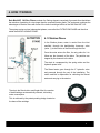
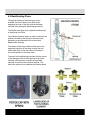
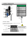
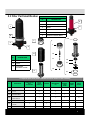
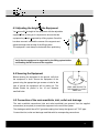
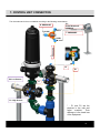
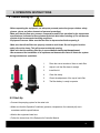
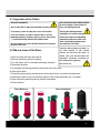
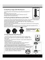
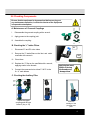
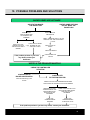
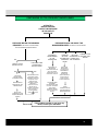
1X2 TABLE OF CONTENTS 1. Symbols …..…………………..………………………………………………………………………………………....………….….…..3 2. Important Information……….…………………………………………………………………………………………………..………...4 3. Introduction.....……….……..………………………………………………………………………………………….………..…….…...5 4. How it Works...……….……..……………………………………………………………………………………..…………...…….…….6 5. 4.1 Filtration Phase……………..………………….……………………………………………….………………………..…….6 4.2 Backflushing Phase………………………………………………………………………………………………..…….……7 Product Identification……..…..………………………………………….……………………………………………………..…..……..8 5.1 Assembly Part Identification .……………………………………………………………………………………..….……..…8 5.2 Product Labeling.……………………….……………………………………………………………………………………....8 5.3 Filter Part Identification.……………………………………………………………….…….…………………………..……..9 6. Installation Instructions...……...…………………………………………………………………………………………………………10 6.1 Installation Steps…………………………..……………………….…….…………………………………………….……..10 6.2 Adjusting the Height of the Equipment..……………………………….……………………………………….…..…….....10 6.3 Securing the Equipment……….………………………………………………………….………………………...….….…10 6.4 Connection of the main manifolds, inlet, outlet and drainage…...…………………...……………….………….…….....10 7. Control Unit Connection………………………………………………………………………………………………………………….10 8. Operation Instructions………………………………………………………………………………………………………………........10 8.1 Before Starting –Up……………..…………….…………...…………………………………….……………………………10 8.2 Start-Up……………..………………..………….………………….……………………………………….…………………10 9. Maintenance…………………………………………………………………………………………………………………………….…10 9.1 Inspection of the Filters ………….…….……….………...……………………….………………………………..………....15 9.2 Manual Clean of the Discs ……..………….………………..……………………………………..……………………...….15 9.3 Checking o-rings in the Filter Element.. …….…………………………………………..………………………..……...….16 9.4 Checking the Removable Elements of the Filter.……………....…………………………………………………………. 16 9.5 Inspecting the Piston Element …………………..….…………….…………………………………………….….…….….16 9.6 Checking Component s…………………………..……………..…….……………………………………………........…...17 10. Possible Problems and Solutions……………………………………………………………………………………………….……….18 11. Warranty……………………………………………………………………………………………………………………………..…….. 20 2 1. SYMBOLS The Warning and Safety Information provided are guidelines only; use all necessary security and accident prevention methods to guarantee your security. The improper use of the equipment may cause injury to people, damage to property or the environment. Improper use or modification of the equipment voids its warranty System of symbols used in this manual: Failure to obey the instructions and warnings could cause injury to people, damage to the equipment or to the surrounding areas. Failure to obey the instructions and warnings could cause serious injury and an electrical hazard. 3 3 2. IMPORTANT INFORMATION Rain Bird filtration equipment has been designed to filter water, in accordance with the operating conditions outlined in this manual and the label on the equipment. • Rain Bird filtration systems are NOT designed for the filtration of hazardous liquids (such as those specified in section 2 of article 2 of the Executive Committee 67/548/CEE, 27th June 1967) or liquids for food use. • This equipment has been designed and manufactured to satisfy the requirements communicated to the manufacturer by the customer. Any change in its use could cause damage not covered by the warranty. • Save this manual so the user of the equipment can familiarize themselves with it. • These are general instructions for safe operation of the equipment. These instructions are not a complete list; the user must adopt as many security measures as necessary to guarantee their safety. • Follow the instructions described in this manual. • Do not open the filter clamp when the equipment is pressurized, it could cause serious injury to people, the equipment or to the surrounding area. • Do use adequate personal protective equipment (proper working clothing, safety glasses, steel toed boots and other elements of personal protection). • Determine the chemical compatibility between the equipment's materials and the characteristics of the water to be filtered. • Before using the equipment, make sure that all the covers are properly closed and the connections are in good condition. • Make sure that the equipment is depressurized by reading the gauges (0 PSI) on the filters inlet and outlet manifold before exposing the interior of the equipment to atmosphere (before opening any filter, removing any coupling, etc.) • Do not forget to close the safety lock on the clamp. It will prevent its accidental opening. • Do not exceed the maximum pressure or operation intervals (pressure, temperature, PH, and flow rate) indicated in the Technical Data. • In freeze areas, empty the filtration system to prevent damage. 4 3. INTRODUCTION Thank you for selecting a Rain Bird HDF 1X2 Disc filtration system. Please read this manual carefully as it will help you find answers to most of your questions. IF YOU HAVE ANY QUESTION OR NEED ADITIONAL INFORMATION; PLEASE CONTACT US AT (520) 806-5620 or [email protected] Rain Bird HDF Disc Filters systems are subject to strict quality control tests and are manufactured under a production process which complies with the requirements of ISO 9001/2000. Rain Bird is committed to the environment, and Rain Bird HDF Disc Filters Series 2 filtration systems are certified under the Environmental Management System of the standard ISO 14001. This manual includes instructions and warnings for correct installation, operation and maintenance of the equipment. 5 4. HOW IT WORKS Rain Bird HDF 1X2 Disc Filters consists of a filtering element comprised of grooved discs that allows the retention of particles of a size larger than the required filtration grade. The equipment combines the advantages of the disc filters with those of the helico-centrifugal effects of the Rain Bird HDF 1X2. The system carries out two independent phases, one called the FILTRATION PHASE and the other called the BACKFLUSHING PHASE. 4.1 Filtration Phase In the filtration phase, water is carried from the inlet manifold, through the backflushing three-way valve (valve 1), to the interior of the filter through the inlet. Once the water enters the filter, the only paths for it to follow are the channels of the discs. The particles are trapped by the channels in the discs. The stack is compressed by the spring action and the hydraulic power itself. The filtered water goes through the 2” hydraulic valve and proceeds through the rest of the installation. The outlet manifold is responsible for collecting the filtered water and carrying to the exterior. Thanks to the filters helico-centrifugal effect, the number of backflushings are dramatically reduced, minimizing water consumption. This is achieved by the patent-pending design located on the base of the cartridge. 6 4.2 Backflushing Phase Through the feeding of the three-ways valves chamber, the inlet of water to the filter closes, beginning the inner of the filter with the drainage manifold, thus starting the backflushing cleaning. The filtered water given by the Special backflushing T, is introduced in the filter. The available hydraulic power is used to overcome the pressure exerted by the spring on the discs stack, generating a decompression due to the piston displacement (raising). The release of the discs creates rotation due to the tangential projection of the water coming from the feeder bars which at the same time are used as a structural shoulder for the discs stack. The end of the backflushing coincides with the closure of the drainage outlet and the opening of the outlet manifold, allowing water coming from the feeder manifold to come into the interior of the filter. This allows the systems to re-establish the filtration phase. 7 5. PRODUCT IDENTIFICATION 5.1 Assembly Part Identification COMPONENTS Nº 8 1 1 RAIN BIRD HDF DISC FILTER 2 INLET MANIFOLD – GROOVED CONNECTION 3 OUTLET MANIFOLD– GROOVED CONNECTION 4 DRAINAGE MANIFOLD 5 MANIFOLD SUPPORTS 6 3 WAY HYDRAULIC VALVE 2” 7 VICTAULIC COUPLING 2” 8 PRESSURE GAUGE 0 – 10 bar / 145 psi 9 AUXILIARY FILTER ¾” KIT 10 CONTROL UNIT 4 6 7 3 9 5 DESCRIPTION 2 10 5.2 Product Labeling The equipment is identified by two labels, one is placed on one of the main manifolds, the other is placed on the filters. Manufacturer The modification or elimination of this label voids any warranty; and impedes the identification of the Equipment. Model Max. Temperature Year of Manufacturing Max. Pressure Serial number 8 5.3 Filter Part Identification COMPONENTS DESCRIPTION Nº 1 2 5 1 BODY CAP 2 CLAMP 3 BODY 4 MICRON RATING LABEL 5 AUTOMATIC CARTRIDGE 6 SEALING GASKET BODY 6 13 7 3 7 4 10 8 Nº DESCRIPTION 11 7 FRAME PISTON 8 DISCS 9 FILTERING ELEMENT FRAME 14 15 12 9 16 To request spare parts please indicate the serial number of the assembly Nº DESCRIPTION CHECK VALVES WITH ACCESORIES SET OF PISTON GASKETS SPRINGS MAINTENANCE KIT 1 1 FILTERING ELEMENT O-RING FRAME 10 PISTON SPRING 11 PISTON O-RING 13 x 2 2 2 12 ELASTIC RING 1 1 1 13 PiISTON GASKET 92.6 x 100 x 4 1 1 1 14 CHECK VALVE 1 15 SPRING CHECK VALVE 1 16 O-RINGS FRAME FRAME O-RING PISTON GASKET 10 1 1 1 2 2 10 9 6. INSTALLATION INSTRUCTIONS - Installation should be made by QUALIFIED PERSONNEL. - The location for the installation of the equipment should be made on solid ground. - You should take into account the weight of the equipment when you choose to use slings. - Make sure that the length of the lifting system is correct so that the filtration system is in a horizontal position when raised. - Secure the equipment to the lifting system to avoid accidents. - Follow all operation and safety instructions for transporting equipment . 6.1 Installation Steps The Rain Bird HDF 1X2 Disc Filtration System equipment is shipped in a box semi-assembled. Please follow the steps below for a proper installation. 1. Unpack the equipment carefully and check that there no is no evident damage. 2. Confirm that all installation parameters are met in accordance with those of the equipment. 3. You can modify the height of the equipment with the adjustable supports. Once the supports are in place adjust their height as required. Due to the equipment dimensions, the shoulders height should be adjusted so that, the upper part of the drainage manifold is placed at a distance of 33,2" (843 mm) from the ground. The separation between the shoulders should be 560 mm. 4. Screw the stainless steel bushing to the outlets of the three-way hydraulic valves. It is very important to use sealer in the threads of both bushings. 5. Assemble the equipment, connecting the inlet, outlet and drainage manifolds using their connections. 6. Install a glycerin pressure gauge 0-145 psi (0-10) bar to measure the pressure coming into the valve. It is recommended you use liquid sealer or LOCTITE 5331, but not in excess. 7. Place the 2” NPT Cap in the open outlet of the filter base. The cap does not need sealing because it is provided with an o-ring. 8. Place the cartridge in the filter base. Once this is completed, place the lid on the unit and close the clamp. 9. Check all connections of the equipment and secure the base to the ground in order to avoid vibration. To close the filter check for debris on the 0-ring in the base. Carefully install the lid and close the filter clamp. To close the clamp, place the bolt in the grooved seat and adjust the lever then clamp the anti-opening device and thread the saftey screw without forcing it. Regulation of the supports of the Equipment. 10 6.3 Adjusting the Height of the Equipment You can modify the height of the equipment with the adjustable supports. Prior to doing so it is important to be sure that the has been secured, unthread the screws of the supports and adjust the height with the help of the lifting system. The equipment must always be horizontal when positioning. 33,2" (43 mm) equipment is properly supported by a lifting system. Once this Verify that the equipment is supported by the lifting system before unthreading the M10 screws of the supports. 6.4 Securing the Equipment Before securing the equipment to the ground, verify that the equipment is level. Secure the equipment to the ground using the appropriate type screws or bolts for the type of ground the equipment will be resting on. The screws should be placed in the 10 mm diameter manifold holes. LEVEL AND SECURE TO THE GROUND TO AVOID VIBRATION 6.5 Connection of the main manifolds, inlet, outlet and drainage The main manifolds connections (inlet and outlet manifolds) are grooved. Use the supplied accessories (as required) to connect the equipment to the rest of the system. The drainage manifold has a PVC grooved coupling from factory that glues to a 3” PVC pipe. Connect the inlet, outlet and drainage manifolds with its corresponding connections. 11 7. CONTROL UNIT CONNECTION The microtubes and unions are labelled according to the following nomenclature: E1: D: DRAINAGE ELECTROVALVE FEEDING AUTO CLOSE T: PRESSURE T: PRESSURE OPEN E1 E1 P2: Low Presure L1 P1: High Presure * : P1 and P2 are the pressure in the inlet and outlet manifold. Their difference is the head loss of the Equipment. 12 8. OPERATION INSTRUCTIONS 8.1 Before Starting-Up •Before operating the equipment, use adequate personal protection (proper clothes, safety glasses, gloves and other elements of personal protection). •Make sure that the flow rate, pressure, temperature and PH are permitted by the equipments specifications (indicated in the equipment technical data) before starting up. Do not operate outside of the recommended working conditions. •Equipment Pressure: Make sure that the filter is depressurized before opening it. •Make sure that all the filters are properly closed to avoid leaks. Do not forget to lock the safety clip on the clamp. This will prevent accidental opening •Make sure that the auxiliary filter key is opened before starting-up the equipment •We recommend the installation of an upstream and downstream valve to isolate the system during maintenance operations. 1. Place the correct number of discs on each filter. 2. Adjust it until the filter base is straight 3. Install the lid. 4. Close the clamp. 5. Check the adjustment of the cap of each filter. 6. The filter battery is ready to operate. 8.2 Start-Up Connect the pumping system for the water inlet Make sure that the Operation Conditions (pressure, temperature, flow rate and pH) are in accordance with the specifications. Monitor the equipment head loss. Follow the instructions of the Equipment's Controller Manual. 13 9. MAINTENANCE Maintenance of the Equipment. The maintenance intervals depend on the operating conditions, characteristics of water to be filtered, length of operation, number of backflushings, recuperation of the differential pressure after the backflushings. Rain Bird recommends maintenance be performed every three month for components which means the disassembly of the filtering element. The actual frequency should be determined by the user according to the particular characteristics of their installation. • Be sure the equipment is depressurized before exposing the interior of the equipment to the atmosphere. • All maintenance should be performed by a qualified professional. • The maintenance frequency should be determined by the user according to the particular conditions of their installation. Below are some general maintenance recommendations: • Every time you start the equipment perform a visual inspection • Do not allow particles to dry in the discs. Activate a backflush just before stopping the equipment, if it will not be used for an extended period of time. • Watch the equipment head loss as well as its recovery after backflushes. DAILY ACTION 1. Visual inspection of the equipment 2. Check for leakage in the equipment 3. Check the Operation Conditions (pressure, temperature, flow rate, PH). 4. Evaluation of the equipment head loss (P1* - P2*) PERIODIC ACTION 1. Check the base o-ring 2. Check the filters cleaning state. If they are very dirty, clean the discs manually. 3. Manually activate a backflush to check operation of the backflushing phases to confirm all the stations are operating correctly. 4. Check gaskets. 5. Check the elements of the piston. 6. Check ¾” intake filter 7. Check ¼” intake filter. 8. Maintenance of grooved couplings. 14 9.1 Inspection of the Filters •Pressure Equipment: •Be sure the filter is depressurized before opening it. •If necessary, clean only the discs in an acid solution. •If an acid solution is used to clean the discs, use the adequate protection (clothes, glasses, gloves, face shield ...) Consult the Safety Sheet of the product used. •Do not contact any part of the filter with the acid solution except for the discs •Do not mix discs from different filters to avoid changes in the number of discs per filtering element. •Placing the filtering element improperly can cause breakage. •Check the chemical compatibility between the lubricant used in the base of the filtering element and the materials of the filter. Clean the discs using clean water. or 9.2 Manual clean of the Discs an acid solution if you cannot remove the dirt from the discs. In 1.Open the clamp and take away the lid 2.Remove the filtering element carefully. 3.Turn the piston until it is released; take away the piston. 4.Take away the discs which case you should follow the protection measures according to the Safety Sheet regarding the acid to use. 5.To assemble the filtering element proceed the other way round. 6. Place all the discs 7.Thread the piston making a soft pressure at the same time it is turned to its adjustment. 8.Lubricate the base o-ring of the filtering element, with neutral petroleum jelly if possible. 9.Place the filtering element pushing carefully downwards 10.Close the filter. Discs Removal Discs Installation 15 92.6x100x4 O-RING 9.3 Checking o-rings in the Filter Element: 1.Thread the piston of the filter element using a light pressure and turn to adjust. 2.Lubricate the area of the O-rings 3.Inert the filter element pushing carefully in the base of the filter. 4.Replace the lid and close the clamp 9.4 Checking the Removable Elements of the Filter: 103x4.00 O-RING 1.Unscrew the screws of the filtering element base with a number 17 box wrench. Always begin by unscrewing two opposite screws. Hold the spring retainer while unscrewing. 2.Remove the spring holder, the spring and the disc cap. Clean carefully with water. 3.Correctly fit all the pieces on the bars. 4.Manually replace the opposite screws, then use the wrench; thread the rest of screws manually and then use the wrench. 5.Lubricate the base of the filter element O-ring, with a product chemically compatible with the material of the filter. Insert the filtering element pushing carefully. Do not force the screws in the assembly, you can damage the threads. 9.5 Inspecting the Piston Elements: 1.Remove the elastic ring from the washers with a pair of straight nosed pliers by inserting the tips in the ring holes and opening. Separate L piece from H piece. 2.Check the two o-rings housed in the piece L. Also, check the washers and the spring of piece H. 3.Apply lubricant in the threaded rod of piece H. 4.Install one washer in the spring and the other in the rod of piece H. 5.The two o-rings in the interior housings of the L pieces. 6.Install piece L on the axis of piece H. Fit the elastic ring on the axis of piece L using the pliers until it seats in the groove of the rod. PIECE H Petroleum Jelly Place the piston in the filter element, lubricate the base of the filter element with a product chemically compatible with the material of the filter and insert the filter element; pushing it carefully into the base of the filter. PIECE L VASELINA 16 9.6 Checking Components Be sure that the equipment is depressurized before carrying out any maintenance operation, in which the interior of the equipment is exposed to atmosphere. A. Maintenance of Grooved Couplings I. Disassemble the grooved coupling with a wrench. II. Apply grease to the coupling joint. III. Assemble the coupling. B. Checking the ¼” Intake Filters P1 I. Disconnect P1 and P2 micro tubes II. Remove the ¼” intake filters on the inlet and outlet manifolds with a wrench P2 III. Clean them IV. Replace the ¼” filter on the manifolds with a wrench, applying sealer to the threads V. Connect the command micro tubes P1 & P2 to the 8 x ⅛” male elbows Applying too much Sealer or forcing the threads may damage them C. Checking the Auxiliary Filter 1º 2º Unbolt the upper coupling and the one below it (key n. 22) Disconnect Clean the cartridge of the punched steel plate 17 10. POSSIBLE PROBLEMS AND SOLUTIONS BACKFLUSHES ARE NOT MADE ANY STATION MAKES THE BACKFLUSH COMPLETE OR PARTIAL REDUCTION OF FEEDING IN THE COMMAND ONE OR SOME STATIONS DO NOT MAKE THE BACKFLUSH NON-OPERATIVE CONTROLLER VERIFY THE MAINS SUPPLY OF THE CONTROL UNIT AND THE FEEDING FUSE* VERIFY THAT THE FEEDING VALVE OF THE INTAKE FILTER IS OPENED CLEAN THE FILTERING ELEMENT OF THE AUXILIARY FILTER. CHECK OUTPUTS FUSES* CHECK SOLENOIDS If the problem persists or you have any doubt, contact your distributor. CHECK HYDRAULIC VALVES WATER IN THE DRAINAGE MANIFOLD CHECK THE CONTROLLER SITUATION CONTROLLER IN BACKFLUSH PROCESS Wait until backflushing cycle is finished Water still remains in the drainage CONTROLLER FILTRATION PROCESS INSPECT EACH OF THE COMMAND MICROTUBES WHICH FEED THE HYDRAULIC VALVES CHAMBERS PRESENCE OF FLUID THROUGH ANY OF THE MICROTUBES WHICH FEED THE VALVES CHAMBERS CHECK THE CORRESPONDING SOLENOID THERE IS NO FLOW OF FLUID IN THE MICROTUBES WHICH FEED THE VALVES CHAMBERS CHECK THE CORRESPONDING HYDRAULIC VALVE If the problem persists or you have any doubt, contact your distributor. 18 CONTINUOUS OR TOO FREQUENT BACKFLUSHES ACTIVATE A BACKFLUSH AND CHECK THE PRESSURE IN THE OUTLET MANIFOLD PRESSURE BELOW THE MINIMUM REQUIRED. See section “Technical Data” PRESSURE EQUAL OR ABOVE THE MINIMUM REQUIRED. See section “Technical Data” from the Filtration Equipment Manual NO DOES IT HAVE A MASTER VALVE? NO CHECK THE INSTALLATION (POSSIBLE LEAKS) INAPPROPRIATE MEASURE OF THE FEEDING PUMP INLET FLOW SUPERIOR TO THE ONE ESTIMATED IN DESIGN YES CHECK THE PUMP SYSTEM WHEN BACKFLUSHING YES THE MASTER VALVE DOES NOT WORK PROPERLY Check the components of the sustaining valve according to section Maintenance Instructions from the Manual and the regulation of the Relief Pilot according to section Operating Instructions from the Manual INCORRECT PROGRAMMING OF THE CONTROLLER TOO SHORT OF BACKFLUSH DURATION. Raise the value. See section “Backflushing time of each station” from the. TOO SHORT TIME BETWEEN BACKFLUSHES. Rise the value. See section “Time between backflushes phases” from the Control Unit Manual RUNNING FLOW PROBLEM INFLUENT WITH THE WATER QUALITY HIGHRER THAN DESIGN DIFFERENTIAL LOWER THAN PRESSURE THE ESTIMATED GAUGE CHECK THE REGULATED VALUE IN THE DIFFERENTIAL PRESSURE GAUGE. See section “Differential Pressure Gauge Delay” from the Control Unit Manual CHECK CONNECTIONS OF THE DIFFERENTIAL PRESSURE GAUGE If the problem persists or you have any doubt, contact your distributor. 19 11. WARRANTY Rain Bird Filtration Products Professional Customer Satisfaction Policy Terms and Conditions Rain Bird guarantees that its Filtration Products will be free of manufacturer defects for one year from date of authorized start-up but not beyond sixteen months from date of invoice. Start-up or service by other than Rain Bird authorized personnel will void these terms and conditions. Provided that all installation, start-up and operation responsibilities have been properly executed, Rain Bird will replace or repair, at Rain Bird’s option, any part found to be defective under normal recommended use during this period. Repairs performed and parts used at Rain Bird’s expense must be authorized by Rain Bird prior to repairs being performed. Upon request, Rain Bird shall provide advice on trouble-shooting a defect during the effective period of this Customer Satisfaction Policy. However, no service, replacement or repair under this Customer Satisfaction Policy will be rendered while the customer is in default of any payments due to Rain Bird. Rain Bird will not accept responsibility for costs associated with the removal, replacement or repair of equipment in difficult-to-access locations. Difficult-to-access locations include (but are not limited to) locations where any of the following are required: 1) 2) 3) 4) 5) 6) 7) Cranes larger than 15 tons Divers Barges Helicopters Dredging Roof removal or other such construction/reconstruction requirements Any other unusual means or requirements Such extraordinary cost shall be the responsibility of the customer, regardless of the reason requiring removal of the equipment from service. The terms and conditions of this Customer Satisfaction Policy do not cover damage, loss or injury caused by or resulting from the following: 1) 2) 3) 4) 5) 6) 7) 8) 9) 10) 11) 12) 13) 14) 15) Misapplication, abuse, or failure to conduct routine maintenance (to include winterization / winter lay-up procedures). Pumping of liquids other than fresh water as defined by the U.S. Environmental Protection Agency, unless the Filtration Products quoted by Rain Bird specifically lists these other liquids and their concentrations. Use of pesticides (to include insecticides, fungicides and herbicides), free chlorine or other strong biocides. Exposure to electrolysis, erosion or abrasion. Use or presence of destructive gases or chemicals unless these materials and their concentrations are specified in the Rain Bird quotation. Electrical supply voltages above or below those specified for correct Filtration Products operation. Electrical phase loss or reversal. Use of a power source other than that specified in the original quotation. Non-WYE configured power supplies such as open delta, phase converters or other forms of unbalanced three phase power supplies (if used). Improper electrical grounding or exposure to incoming power lacking circuit breaker or fused protection. Using the control panel as a service disconnect. Lightning, earthquake, flood, windstorm or other Acts of Nature. Failure of Filter packing seal (unless the failure occurs on initial start-up). Any damage or loss to plants, equipment or groundwater or injury to people caused by the failure of or improper use of an injection system or improper concentration of chemicals or plant nutrients introduced into the Filtration Products by an injection system. Any failure of nutrient or chemical storage or spill containment equipment or facilities associated with the Filtration Products location. The foregoing terms and conditions constitute Rain Bird’s entire Customer Satisfaction Policy. Rain Bird does not offer any other or additional warranty, with respect to the pumping system or its components. Rain Bird makes no implied warranty, with respect to fitness for a particular purpose or merchantability of the pumping system or its components. In the case of any components or injection systems manufactured by others (as noted on the Filtration Products Quotation), there is no warranty provided by Rain Bird and these items are covered solely by and to the extent of the warranty, if any, offered by the manufacturer. Rain Bird shall not be liable to the customer or any other person or entity for any liability, loss or damage caused or alleged to be caused, directly or indirectly, by the Filter system or by any injection system. Rain Bird shall not be responsible for incidental, consequential, collateral or indirect damages or loss of profit or damages related to the customer’s business operations, nor for those caused by Acts of Nature. In no case and under no circumstances shall Rain Bird’s liability exceed the Rain Bird Corporation’s net sale price of the Filter system. Laws concerning customer warranties and disclaimers vary from state to state, and therefore some of the foregoing limitations may not apply to you. 20 Request your spares to: Rain Bird Corporation Tel. (520) 741-6100 Fax: (520) 741-6191 E-mail: Filters@Rain Bird.com http:// www.RainBird.com RAIN BIRD DISC FILTER ASSY-DISC Series User’s Manual – 2013/00 4.2. Identification of the product. 21