1
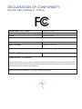
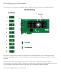
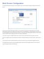
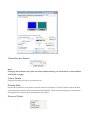
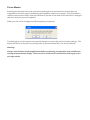
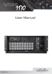
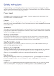
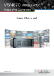
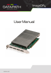
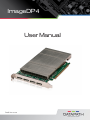
ImageDP4
User Manual
Draft V01.00.00
Contents
DECLARATION OF CONFORMITY 3
Safety Instructions4
Introduction5
ImageDP46
Hardware Installation 7
Installing an ImageDP48
Multi Screen Configuration 12
Appendix 1 - Defining Custom Modes 18
Appendix 2 - Screen Order 19
Index
21
FCC Compliance ImageDP4
Federal Communications Commission Statement
This device complies with FCC Rules Part 15. Operation is subject to the following two conditions:
This device may not cause harmful interference, and
This device must accept any interference received, including interference that may cause undesired
operation
This equipment has been tested and found to comply with the limits for a Class B digital device,
pursuant to Part 15 of the FCC Rules. These limits are designed to provide reasonable protection
against harmful interference in a commercial, industrial or business environment. This equipment
generates, uses and can radiate radio frequency energy and, if not installed and used in accordance
with the manufacturers instructions, may cause harmful interference to radio communications.
However, there is no guarantee that interference will not occur in a particular installation. If this
equipment does cause harmful interference to radio or tele¬vision reception, which can be
determined by turning the equipment off and on, the user is encouraged to try to correct the
interference by one or more of the following measures.
•
Re-orient or relocate the receiving antenna
•
Increase the separation between the equipment and the receiver
•
Connect the equipment to an outlet on a circuit different from that to which the
receiver is connected
•
Consult the dealer or an experienced radio/TV technician for help
Warning! Any changes or modifications to this product not expressly approved by the manufacturer could void any assurances of safety or performance and could result in violation of Part 15 of
the FCC Rules.
Reprinted from the Code of Federal Regulations #47, part 15.193.1993. Washington DC: Office of the Federal Register, National Archives and Records
Administration, US Government Printing Office.
DECLARATION OF CONFORMITY
Per FCC Part 2 Section 2. 1077(a)
Responsible Party Name:
Address:
Phone:
Datapath Limited
Alfreton Road, Derby
+441332-294441
Hereby declares the product:
Product Name:
Model Number:
Four Head PCIe Graphics Card
ImageDP4 (DGC149)
Conforms to the following specifications:
FCC Part 15 Subpart b
Class A Digital Device
Supplementary Information:
This device has been shown to be in compliance with and was tested in accordance with the measurement procedures specified in the Standards & Specifications listed above and as indicated in the
measurement report number: 9G2498GUS2
Representative Persons Name: Tony Jones, Operations Director
Safety Instructions
To prevent damage to your Datapath product or injury to personnel operating the equipment, please
read the following safety precautions prior to operation. These instructions should be made available to
all those who will use and operate Datapath products.
Power Supply
All Datapath products require a mains power supply. This power supply must be disconnected when
equipment is being upgraded or relocated.
Cables
Do not expose cables to any liquids; doing so may cause a short circuit which could damage the
equipment. Do not place heavy objects on top of any cables as this can cause damage and possibly lead
to exposed live wires.
Ventilation
All computer equipment should be located in a well ventilated area. All ventilation holes on the computer casing must be kept clear of any obstruction at all times. Failure to do so will result in the system over
heating and damaging your equipment.
Working Environment
The equipment should be located in an environment free from dust, moisture and extreme changes
in temperature and should be placed on a stable and solid work surface. Liquids (hot/cold drinks etc)
should not be placed near the equipment as spillage could cause serious damage.
Gas/Flammable Liquids
Electronic equipment should never be used in the presence of gas or any flammable liquid, doing so
could result in an explosion or serious fire.
Smoke/Unusual Smells
Should you notice smoke or unusual smells being emitted from your computer, turn off and unplug the
system from the mains supply. The system should then be passed to a qualified technician for
inspection. Continued operation could result in personal injury and damage to property.
Maintenance
Maintenance should only be carried out by competent technicians, any Datapath plug-in cards that are
physically damaged should be returned to Datapath for repair using Datapath RMA procedures.
Disposal
At the end of life all Datapath products should be disposed of as per local laws and regulations dictate.
In UK contact Datapath to arrange disposal. Our WEE registration number is WEEE/AA0005ZR.
Introduction
The Datapath ImageDP4 multi screen graphics accelerator is single slot PCIe card for displaying Windows across multiple screens as one extended desktop.
The ImageDP4 has two graphics processor units (GPU) each with 256Mbytes of DDR2 RAM. Half of
this RAM is accessible from the PCIe bus, the rest is accessible only by the GPU.
All cards in the ImageDP4 range feature:
•
Analog or DVI-D outputs.
•
Supports VESA modes up to 1600 x 1200 and non-VESA modes up to 2048 x 1536.
•
Full hardware cursor support for flicker free Windows cursors in all modes.
•
Multiple card hardware support for multiple screen systems.
Specifications:
Card format
Card size
Max output resolution
Max number of cards per system
Frame buffer memory
Max current at +3.3V
Max current at +12V
Max Power
Operating temperature
Storage temperature
Relative humidity
MTBF
Warranty
4 lane PCI express
110mm x 197mm
4x1920x1200 DVI/RGB
10 (40 display channels)
2x 256MB (512MB total)
0.25A
1.7A
22 watts
0 to 35 deg C
-20 to +70 deg C
5% to 90% non-condensing
88,293hrs
3 years
ImageDP4
The ImageDP4 PCIe graphics card supports the display of RGB, SD and HD video capture windows. It is
ideal for high end video/data walls, signage or display wall applications.
•
4 Port PCI express graphics card (x4 lanes)
•
Analog RGB or DVI outputs up to 4 1920x1080x24bits/pixel
•
Low power
•
High Performance 2D and 3D graphics
•
High performance DMA image load (720MB/s)
•
Support for Windows® Vista, XP, Server 2008, and Windows® 7 (Server 2008 or
Windows® 7 64-bit required for greater than 8 screen support).
•
RGB, SD and HD video window support by adding the VisionRGB-E1, VisionRGB-E2,
VisionSD8 or VisionSD4+1 capture cards
•
Up to 10 cards per system for a maximum of 40 displays. In order to use 3 or more ImageDP4 cards
you must use a Vision800 system or a system based on the Express9 backplane.
Hardware Installation
This section deals with installing ImageDP4 cards and spreading the Windows desktop across all the
screens. If you are intending to use the ImageDP4 cards with other Datapath products, you should follow
this section to get the Windows desktop working correctly first.
System Requirements
•
A Pentium PCIe bus computer with sufficient free PCIe slots.
•
A least 1GByte of RAM.
•
Windows® Vista, XP, Server 2008, Windows® 7 (Server 2008 or Windows® 7 64-bit required for greater
than 8 screen support).
Unpacking
Your packing box should contain the following items:
•
The ImageDP4 PCIe plug-in card.
•
Two VGA-Y-cables or two DVI-Y-cables depending on model purchased
•
A Genlock cable.
•
Installation CD-ROM
Installing an ImageDP4
It is recommended that all ImageDP4 cards and any Vision cards are installed in the system prior to
installing the drivers. Otherwise as cards are installed the drivers may need to be reinstalled as the card’s
PCI bus numbers change
Note:
All plug-in cards are static sensitive and packed in antistatic materials. Please keep the card in its
packaging until you are ready to install.
It is recommended that you do not discard the packing box until you are completely satisfied with
the ImageDP4 card, and it is fully installed and working correctly. We also recommend that you
make note of the serial number of the card in a prominent place before you plug the card into the
computer. This should hasten any query should you need to contact our Technical Support Department. The serial number is displayed on the card and the box label.
•
Power down the PC (including peripherals), switch off at the mains and disconnect all the
cables connected to the computer, noting the positions for accurate reconnection. Remove the PC
cover
•
Locate a vacant PCIe (x4 or above) slot for the ImageDP4 on the motherboard and remove the backing plate (retain all screws). If in doubt consult your motherboard documentation to
correctly identify a PCIe (PCI-express) slot. If the card is forced into a 32 or 64 bit PCI or PCI-X slot it
will be irreparably damaged when the system is powered up and the warranty will be void.
•
Remove the card from its packaging and secure it firmly into the empty PCIe slot. Extreme care
should be taken when securing the card into the slot as some motherboards may have
components that impede the siting of the card
Screw the card bracket to the back panel of the PC and replace the cover
Using the splitter cables provided, connect screens to all the outputs from the card. If there are other
graphics devices in the system, connect screens to them (even if you don’t intend to use all the outputs in
your final configuration)
Switch all the screens on then switch the machine on
You should see the boot messages on one of the screens. The screen on which the system will boot is dependent on how the system is configured and the motherboard BIOS. It is not possible to control which
of the ImageDP4 heads the system will boot on.
Installing the Display Drivers
Once the ImageDP4 card has been installed and the boot messages are appearing on the correct monitor,
you can start Windows.
Log on as a user with administrative access rights.
The Found New Hardware Wizard will announce that new hardware has been found.
Do not use the Found New Hardware Wizard to install the ImageDP4 drivers.
Install the display drivers from the Software Installation Suite CD supplied with the ImageDP4 card. The
display drivers are required to be installed in Safe Mode.
If your final configuration has less than four screens select the number of screens required, otherwise
select four screens.
Restart the machine.
When Windows starts up, the desktop should be spread over all the screens connected to the ImageDP4.
Installing the Additional ImageDP4 Cards
As the number of required screens increase, the likelihood of reaching a system limitation or encountering
a problem increases. The system limitations are the amount of address space available and the capacity of
the power supply.
Please consult Datapath support if you have any problems installing multiple cards.
Power
The amount of current a power supply can deliver on each voltage rail is limited. Often there is also a limit
on the total power.
Each ImageDP4 card requires 0.25A at +3.3V and 1.7A at +12V.
You can calculate the amount of current and the amount of power required for the ImageDP4 cards. For
example, the requirements for a 24-screen system of ImageDP4 cards is calculated as follows:
Current
+3.3V 6 x 0.25A = 1.5A
+12V 6 x 1.7A = 10.2A
Power
( 3.3V x 1.5A ) + ( 12V x 10.2A ) = 127.35W
These are the requirements for the ImageDP4 cards; you must take into account the requirements of all
the other devices in the system.
Connecting up to 40 Screens
To connect up to 40 screens to ImageDP4 cards, configure the links as shown in the diagram below:
The links control the order in which the display driver uses the ImageDP4 cards. Knowing the order in
which the ImageDP4 cards are used is useful when connecting the screens and the outputs from video
switches.
Note that if you have not configured your system to boot-up on on-board VGA graphics device or
another plug-in VGA card the system will boot-up on the master head of one of the ImageDP4 cards but it
is not possible to control which output will be used, this is motherboard BIOS dependent.
Insert the ImageDP4 cards into the PCIe slots.
Continue to connect the genlock cables J3 (Out) to J2 (In) until all cards are connected.
Connect the screens to the cards. The first card should be connected to the first group of four screens; the
second should be connected to the second group of four screens and so on.
Switch the screens on then switch the machine on.
Log on as a user with administrative access rights.
The Found New Hardware Wizard will announce that new hardware has been found. This will happen
once for each slave ImageDP4 card you have added to the system. Do not use the Found New Hardware
Wizard to install the ImageDP4 drivers.
The Windows desktop should appear on the four screens attached to the first card as it did after the
display driver had been installed for the first ImageDP4 card.
You need to install the display driver again. This time you should specify the number of screens you wish
to use.
Restart the machine.
The Windows desktop should now be spread across the number of screens you specified.
Multi Screen Configuration
To change the display settings for the ImageDP4 cards, use the Display Properties dialog in the Control
Panel.
If you have more than one graphics device in your machine, the Display Settings allow you to control
which graphics devices are used and what their position on the desktop is. There should be a monitor icon
for each ImageDP4 card and at least one monitor icon for each of the other graphics devices in the system
(there is a limit to the number of monitor icons that are displayed).
If you are using a non-ImageDP4 device as a control screen, make that device the primary monitor.
The first ImageDP4 device should have the Extend my Windows desktop onto this monitor control selected.
Do not select Extend my Windows desktop onto this monitor for any of the other ImageDP4 devices.
To change other properties of the ImageDP4 display, select the first ImageDP4 device, click on the Advanced settings and go to the TWIN tab.
Resolution per Screen:
Note:
Changing the resolution may alter the colour palette settings, so check that it is correct before
clicking OK or Apply.
Colour Palette:
Select the number of colours you want to use.
Refresh Rate:
Use the drop down arrow to select a refresh rate for the desktop. Only the refresh rates available
at the selected resolution and colour depth are displayed. The maximum settings are restricted to
the capabilities of the screens connected to the system.
Source of Mode:
When the TWIN tab is selected, the display driver reads the EDID information from each monitor and
reads the Registry to find detailed display timing information.
The Source of Mode group box shows which mode sources are available for the selected resolution and
colour depth.
The Source of Mode has 4 options.
Default
Monitor timing information from the display driver’s internal tables.
Custom
Monitor timing information from the Registry. (See Appendix 1: Defining Custom Modes for details)
Monitor (Master)
Monitor timing information from the monitor attached to output 1 of the Master ImageDP4 is used for
all outputs.
Monitor (Each)
The monitor timing information from each monitor is used for the output connected to that monitor.
No. Screens
Change the number of screens the display driver uses. You should always install the driver (using install.
exe) for the maximum number of screens you want to use.
Screen Arrangement
Use the drop down menu to select the type of screen arrangement you require. The illustration in the
Monitor Configuration box will reflect your choice.
Force DVI Output
When the Datapath display driver initializes it reads the EDIDs of the attached screens to determine if
the DVI (digital) or analog outputs should be used. If no monitor EDID is read then this control is used to
decide which output to enable.
If the check box is in an indeterminate state it signifies that the enabled outputs are not as requested by
the user. This will occur if a mixture of analog and digital screens are used or if the type of monitor used
is different to the Force DVI state.
If the check box state is changed the Apply button will become active, click on Apply to force the required output.
Since the DVI (digital) output supports a lower pixel dot-clock frequency than the analog output, the
resolution dialog is updated when the check box is changed to reflect the resolutions supported by the
active output.
Prune Modes
Enabling this check box limits the resolutions displayed in the resolution box to those that are
supported by all of the screens attached to the ImageDP4 card’s active outputs. This information is
read from the monitor EDIDs when the TWIN tab is opened. If the state of this check box is changed
then the resolution control is updated.
When you click on OK or Apply the following dialog is displayed:
This dialog gives you the option to accept the changes or restore the previous display settings. The
display will return to the previous settings after 15 seconds should Yes or No not be selected.
Warning!
Always close all video window applications before performing any operation that modifies the
settings of any attached display. Failure to do so could result in the machine locking up and requiring a reboot.
Datapath Limited
Datapath has a long and very successful history in the computer graphics industry. Datapath has been
designing and supplying high performance, high quality graphics display systems to the world’s largest and most demanding companies and institutions since 1982. Datapath was one of the founding
companies of multi-screen Windows acceleration using single and multi board solutions. Now using
the very latest display technology Datapath offers some of the world’s leading multi screen graphics
accelerators for the most demanding applications.
As new technology advances, so we at Datapath improve the performance and functionality of both
our hardware and software to give our customers more. Following a continuous development program, we pride ourselves on our support and responsive nature towards all our customers and their
changing needs. As more sophisticated equipment and techniques become readily available, so we
are there to exploit the power and potential that this technology presents.
Technical Support
Registered Users can access our technical support line using, email, and the Support page on the Datapath Web Site, usually with a response within 24 hours (excluding weekends).
Via Email
Send an email to [email protected] with as much information about your system as possible.
To enable a swift response we need to know the following details:
•
Specification of the PC - including processor speed
•
Operating System
•
Application Software
•
Datapath Hardware / Software
•
The exact nature of the problem - and please be as specific as possible.
Please quote version and revision numbers of hardware and software in use wherever possible.
Copyright Statement
© Datapath Ltd., England, 2011
Datapath Limited claims copyright on this documentation. No part of this documentation may be
reproduced, released, disclosed, stored in any electronic format, or used in whole or in part for any
purpose other than stated herein without the express permission of Datapath Limited.
Whilst every effort is made to ensure that the information contained in this User Manual is correct,
Datapath Limited make no representations or warranties with respect to the contents thereof, and
do not accept liability for any errors or omissions. Datapath reserves the right to change specification
without prior notice and cannot assume responsibility for the use made of the information supplied.
All registered trademarks used within this documentation are acknowledged by Datapath Limited
UK Headquarters and Main Sales Office
Datapath Ltd.,
Alfreton Road,
Derby, DE21 4AD, UK
Tel: +44 (0) 1332 294441
Fax: +44 (0) 1332 290667
Email: [email protected]
www.datapath.co.uk
Appendix 1 - Defining Custom Modes
Defining custom modes is carried out using the Custom Mode Utilities tool that can be found on the
Datapath CD. The latest version may also be downloaded from the Datapath website:
www.datapath.co.uk
The Custom Modes tool is a utility for defining custom modes that can be generated by the ImageDP4
graphics card. The custom modes tool must be used on a system where the active display driver supports
custom modes. To generate a custom mode the following values must be entered into the utility
application dialog box:
•
X Resolution - The active display width in pixels.
•
Y Resolution - The active display height in lines.
•
Refresh - The refresh rate displayed in the Display Properties dialog. Also used for calculating the
dot-clock if no value is provided.
•
Horizontal Front Porch - The horizontal front porch in pixels.
•
Horizontal Sync Width - The H-Sync width in pixels.
•
Horizontal Back Porch - The horizontal back porch in pixels.
•
Vertical Front Porch - The vertical front porch in lines.
•
Vertical Sync Width - The v-sync width in lines.
•
Vertical Back Porch - The vertical back porch in lines.
•
Horizontal Sync Polarity - 0 = negative, 1 = positive
•
vertical Sync Polarity - 0 = negative, 1 = positive.
•
Dot Clock (optional) - The pixel dot-clock in KHz. This is calculated from the Refresh rate if not
provided.
Note:
If a new mode is created or an existing one amended, then the Display Properties dialog must be closed
and re-opened to ensure the new values are refreshed in the display driver.
Appendix 2 - Screen Order
Connection of Screens
The first card to be initialized generates the picture for the top left monitor in the wall of screens, plus the
three adjacent screens. The second card drives the next four screens and so on. This sounds simple, but
nevertheless, can be confusing when trying to determine how to assign monitor video cables to the
ImageDP4 out¬puts.
Changing the Order of the Screens
Changing the order in which the screens appear is done using the Wall Control application.
Select Screen Order from the Wall Control Configure menu and in the displayed dialog, click on the screens
sequentially to establish the order you want.
Note:
The new screen order will not be applied until the Wall Control server is re-booted.
Index
A
Analog 6
C
Cables 8
Card format 6
Colour Palette 14
Copyright Statement 17
D
DVI-D outputs 6
DVI-Y-cable 8
F
Force DVI Output 15
Frame buffer memory 6
G
Genlock cables 11
I
ImageDP4-DVI 8
Installation CD-ROM 8
M
Max number of cards per system 6
Max output resolution 6
MTBF 6
O
Operating temperature 6
P
Prune Modes 16
R
Refresh Rate 14
Relative humidity 6
Resolution per Screen 14
S
Screen Arrangement 15
Source of Mode 14
Storage temperature 6
Support for Windows 7
System Requirements 8
T
Technical Support 17
U
UK Headquarters 18
Unpacking 8
V
VGA-Y-cable 8
W
Warranty 6