1
Operation manual
Switching Mode Programmable
Power Supply
with PC Interface
PeakTech® 1885
PeakTech® 1890
Table of Contents
1. Important Safety Instructions and Precautions For Use...............................................……. 1
2. Technical Specifications of SDP Series Power Supply..................................................…... 2
3. Introduction.......................................................................................................................……. 2
4. Control and Indicators.....................................................................................................…….. 3
5. General Operation Principle..........................................................................................……… 3
5.1. Quick Reference of Keypad Functions..................................................................……. 3
5.2. Quick Reference of The Timed and Preset Program.............................................…… 5
6. Operating Instructions......................................................................................................……. 5
6.1. Setting of Operating Mode…………………………………………………………………… 5
6.1.1. Enable/Disable Output.........................................................................….. 5
6.1.2. Lock / Unlock the Keypad and Jog Dial..............................................…... 5
6.1.3. PC Interface RS-232//RS-485 Selection..............................................….. 5
6.1.4. Upper Voltage Limit Setting...............................................................……. 5
6.1.5. Output Enable/Disable at Power Up...................................................…… 5
6.2. Basic Operation……………………………………………………………………………… 5
6.2.1.Setting of Voltage and Current by Jog Dial and UP & DN Key ........…….. 5
6.2.2.Setting of Voltage and Current Using Keypad.....................................…… 5
6.3. Using the Programming Features …………………………………………………………. 5
6.3.1. Timed Programming...........................................................................…… 5
6.3.2. Running the Timed Program................................................................….. 5
6.3.3. Preset Programming............................................................................….. 5
6.3.4. Selecting Preset....................................................................................…. 5
6.4. Setting of Operation Models……………………………………………………………….. 6
6.4.1. Enable/Disable Output………………………………………………………… 6
6.4.2. Lock/Unlock the Keypad and Jog Dial…………………………………….. 6
6.4.3. PC Interface RS-232 / RS-485 selection………………………………….. 6
6.4.4. Upper voltage limit setting…………………………………………………….. 6
6.4.5. Output Enable/Disable at Power Up………………………………………. 6
6.5. Basic Operation……………………………………………………………………………… 7
6.5.1. Setting of voltage and current by Jog Dial and UP & DN Key………….. 7
6.5.2. Setting of voltage and current by using Keypad……………………………. 7
6.6. Using the Programming Feature…………………………………………………………… 8
6.6.1. Timed Programming…………………………………………………………. 8
6.6.2. Running the Timed Program……………………………………………….. 9
6.6.3. Preset Programming………………………………………………………… 9
6.6.4. Selecting Preset……………………………………………………………… 10
7. Maintenance.....................................................................................................................…….. 10
7.1. Recalibration…………………………………………………………………………………. 10
7.1.1. Introduction……………………………………………………………………. 10
7.1.2. Installation of calibration software ………………………………………….. 10
7.1.3. Operating Instructions ……………………………………………………….. 10
7.2. Trouble Shooting ……………………………………………………………………………. 10
8. PC Interface Control User Manual................................................................................……… 10
8.1. Connect a Signal Power Supply to PC via RS-232.................................................…… 11
8.2. Connect Multiple Power Supply to PC via RS-485...............................................…….. 11
8.3. PC Application Software........................................................................................……. 12
8.3.1. What the Application Software will DO ………………………………………… 12
8.3.2. System Requirements ……………………………………………………………. 12
8.3.3. Installation of Software ……………………………………………………………. 12
8.4. Running the Application Software for RS-232 Interface........................................……. 12
8.4.1. Start-up the Application Software for RS-232...........................................……. 12
8.4.2. General Operations.....................................................................................….. 14
8.4.3. Data Logging and Setting Windows in Application Software....................……. 15
8.4.4. The Time Frame Concept of Data Log .......................................................….. 16
8.4.5. Internal Timed Program.............................................................................…… 17
8.4.6. Internal Preset Memory.............................................................................…… 17
8.5. Running the Application Software for RS-485 Interface........................................……. 17
8.5.1. Multi Window Analysis.................................................................................…….. 18
Appendices
Appendix A - SDP Command Set..............................................................................……. 21
Appendix B - RS-232 cable and Connection Information...........................................……. 25
Appendix C - Optional RS-232 to RS-485 Adapter ATR-2485 User Manual............…….. 26
1. Safety Precautions
This product complies with the requirements of the following European Community Directives:
89/336/EC (Electromagnetic Compatibility) and 73/23/EC (Low Voltage) as amended by 93/68/EC
(CE-Marking). Overload protection category II, pollution degree 2.
To ensure safe operation of the equipment and eliminate the danger of serious injury due to shortcircuits (arcing), the following safety precautions must be observed.
*
*
*
*
*
*
*
*
*
*
*
*
*
*
*
*
*
*
*
*
*
*
*
*
This unit must be used within its specified range.
The rated input voltage can be found on the rating label under the unit.
Before plugging into the AC supply outlet, check whether the input rating conform with your local
supply.
Because to use this unit within the specified ambient temperature range listed in the specification
table.
Because the unit is cooled by natural convertion, do not place objects on top to block the
convertion.
User must avoid to place the unit on rear any heat emitting devices or use multiple units in stacked
configuration.
For best result, use the unit in an environment that is as well cross-ventilated as possible.
Do not exceed the maximum permissible input ratings (danger of serious injury and/or destruction
of the equipment).
Replace a defective fuse only with a fuse of the original rating. Never short-circuit fuse or fuse
holding.
Check test leads and probes for faulty insulation or bare wires before connection to the equipment.
To avoid electric shock, do not operate this product in wet or damp conditions.
Comply with the warning labels and other info on the equipment.
Do not subject the equipment to direct sunlight or extreme temperatures, humidity or dampness.
Do not subject the equipment to shocks or strong vibrations.
Do not operate the equipment near strong magnetic fields (motors, transformers etc.).
Keep hot soldering irons or guns away from the equipment.
Allow the equipment to stabilize at room temperature before taking up measurement (important for
exact measurements).
Periodically wipe the cabinet with a damp cloth and mid detergent. Do not use abrasives or
solvents.
The power supply is suitable for indoor use only
Do not operate the meter before the cabinet has been closed and screwed safely as terminal can
carry voltage.
Do not store the power supply in a place of explosive, inflammable substances.
Do not modify the equipment in any way
Opening the equipment and service – and repair work must only be performed by qualified service
personnel
Measuring instruments don’t belong to children hands.
Warning!
For models P 1885 / P 1890, the maximum output voltage is up to 60 V DC. It may be hazards to
touch metal part of the output terminals. User must avoid touching live metal parts of the output
terminals.
-1-
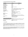
2. Technical Specifications of Power Supplies
Specifications
P 1890
Output voltage
Output current
Rated Output Power
Ripple & Noise (p-p)
Load Regulation
Line Regulation
Input Voltage
Max. Input Power
Power Factor
Display Meter
Meter´s Accuracy
1-20 V DC
1-40 V DC
0-10 A
0-5 A
200 W
30 mVp-p
300 mV
10 mV
100-240 V AC, 50/60 Hz
285 W
≥ 0,9
4 digits – Display LCD Ammeter, Voltmeter and Power Meter
( +/- 1% + 5 counts for range V < 5V, I < 0.5A),
( +/- 1% + 2 counts for range V ≥ 5V, I ≥ 0.5A)
48 x 66 mm
Thermostatic Control Fan
0- 40°C
-Tracking OVP (Over Voltage Protection),
-Current Limiting,
-Over Temperature Protection.
CE EMC -- EN 55011, CE LVD -- EN 61010
193 x 98 x 215 (mm)
3kg
-User's Manual,
-PC Windows® software, Command Set, LabView® Driver,
-RS-232 cable, RS-485 Connector and one 120ohms Resistor
-RS-232 to RS-485 Adapter
-Adjustable Upper Voltage limit,
-Power Factor Correction.
LCD Dimension
Cooling System
Operating Temperature
Protection
Approvals
Dimension (WxHxD)
Weight
Accessory
Optional Accessory
Remarks
P 1885
Remote Programming Specifications
Communications Interface
RS-232 (Single Power Supply), and RS-485 (up to 31 Power
Supplies).
Remote Programming Functionality
Full control of power supply functions and data readback.
Data Logging
Yes, with supplied software.
Baud Rate
9600bps
3. Introduction
This series of Programmable Switching Mode Power Supplies are designed for full remote
programming with data logging functionality. Up to 31 power supplies can be connected via RS- 485. It
is ideal for applications which require various groups of output settings and running periods for
repetitive tests especially with multiple power supplies.
The front panel allows users to all programming and output settings as a stand alone laboratory power
supply.
Full command sets are given in this manual to facilitate the integration of your own control software.
This series of power supplies have obtained the safety approval EN-61010 and EN-55011 EMC
approval for scientific , industrial equipment of the CE directives.
Please keep this manual in a safe place and contact your vendor for any special requirement in
optional accessories for RS-485.
-2-
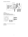
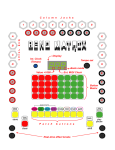
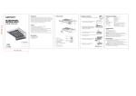
4. Controls and Indicators
Front Panel
1.
2.
3.
4.
5.
6.
2
3
Jog Dial
Up & Down Key
Dual Function Control Key
Red colour positive polarity output terminal.
Black colour negative polarity output terminal
Green colour ground terminal (connected to chassis).
1
5
7
8
10
9
7. Jog Dial
8. AC 100-240 V AC Power Socket with input power fuse.
9. RS-232 Port
10. RS-485 Port
-3-
6
4
5. General Operation Principle
Note: This section contains a condensed overview of the unit. Read this section to quickly get started.
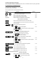
5.1. Quick reference of Keypad Functions
The front Keypad is organised as follows:
(1) Number Keys, UP/DOWN Keys and Jog Wheel
(2) 4 Dual Function Control Keys
The front panel functions are summarized as follows:
Keypad
0
Function
Number Keys, UP/DOWN Keys and Jog Wheel
9
thru
S UP
T DN
Jog Wheel
Section
Press to select numerical values
6.2.2.
Press to ascend the numerical values
Press to descend the numerical values
Rotate to adjust the voltage and current settings
6.2.1.
6.2.1.
6.2.1.
Dual Function Control Keys
SHIFT
Press to access alternate function of the control keys
CLEAR
Press to terminate any input process and the unit will exit to
normal operation
PROG.
thru
0
9
Press to use programming features.
Use
0
to recall the timed program.
1
5.2.
6.3.1.
9
Use
thru
to specify the location of preset program
to be 6.3.3.stored.
Use ENTER to confirm
SHIFT
Press to enter the PC interface selection menu.
You can choose either RS-232 or RS-485
RS-232/485
Use
Use
0
RECALL
thru
9
RS-232/485
to select RS-232 or RS-485
to confirm the settings
ENTER
Press to recall your stored preset or timed program
Use
0
to recall the timed program
Use 1 thru
to recall.
Use
SHIFT
LOCK/UNLOCK
ENTER
SHIFT
6.1.3.
ENTER
9
to specify the location of preset program
6.3.2.
6.3.4.
to confirm
Press to Lock/Unlock the Keypad and Jog Wheel
6.1.2.
Press to confirm the new settings
O/P on/off
Press to Enable/Disable the output
6.1.1.
SHIFT
S
Press to Enable the output at power up
6.1.5.
SHIFT
T
Press to Disable the output at power up
6.1.5.
SPECIAL FUNCTION
SHIFT
0
Press to get to the upper voltage limit setting
Use
Use
0
thru
ENTER
9
to input the numerical values
to confirm
-4-
6.1.4.
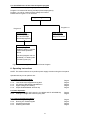
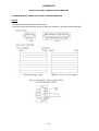
5.2. Quick Reference of the timed and preset program
The unit can store 10 programs (program number 0-9).
Program 0 is reserved for storing 20 steps (timed subprograms).
Program 1 to 9 is for 9 sets of preset voltage and current.
Please refer to Figure 5.2. for structure.
Programming Features
Program 1-9
Program 0
Timed Program
The timed program
can store 20 steps
(timed subprograms)
Preset Program
9 sets of preset
voltage and current
Timed Subprogram
Each subprogram is
capable of storing 1 second
to 99 minutes operation
period.
The timed program can run
repeatedly 1 to 9999 cycles
or infinite cycles ("0").
Figure 5.2. Block Diagram of Timed and Preset Program
6. Operating Instructions
NOTE: This section shows how to perform power supply functions using the front panel.
Operations that you can perform are:
6.1. Setting of Operating Mode
6.1.1. Enable/Disable Output
6.1.2. Lock/ Unlock the Keypad and Jog Dial
6.1.3. PC Interface RS-232/RS-485 Selection
6.1.4. Upper Voltage Limit Setting
6.1.5. Output Enable/Disable at Power Up
Page 5
Page 5
Page 5
Page 5
Page 5
6.2. Basic Operation
6.2.1. Setting of Voltage and Current by Jog Wheel and UP & DOWN Key
6.2.2. Setting of Voltage and Current by Key Pad
Page 5
Page 5
6.3. Using programming features
6.3.1. Timed Programming
6.3.2. Running the Timed Program
6.3.3. Preset Programming
6.3.4. Selecting the Preset
Page 5
Page 5
Page 5
Page 5
-5-
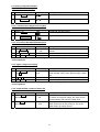
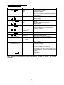
6.4. Setting of Operation Models
6.4.1. Enable / Disable Output
1.
Action
Press SHIFT
2.
Press
LCD-Display
Description
Output ENABLE
Output DISABLE
O/P ON/OFF
6.4.2. Lock/Unlock the Keypad and Jog Dial
1.
Action
Press SHIFT
2.
Press
LCD-Display
Description
Keypad and Jog Dial Locked
Keypad and Jog Dial Unlocked
LOCK/UNLOCK
6.4.3. PC Interface RS-232/RS-485 Selection
Action
LCD-Display Description
SHIFT
1. Press
---232
This will enter into PC interface RS-232/ RS-485
then RS-232/485
485
selection
RS-232/485
2. Press
Press this key to confirm
3. Press ENTER
Press this key to confirm
Note: Whenever to terminate the settings of operation mode, press "CLEAR" to return to
normal operation
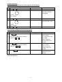
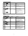
6.4.4. Upper voltage limit setting
Action
Press SHIFT
then 0
LCD-Display
OVER V
25,6
Description
1.
This will enter into upper voltage limit adjustment.
In this example, 25,6 V is the present upper voltage
limit
0 to 9
2.
Use this number key to input your desired voltage
ENTER
3. Press
Press this key to confirm
Note: Whenever to terminate the upper voltage limit settings, press "CLEAR" to return to
normal operation
6.4.5. Output Enable / Disable at Power Up
1.
2.
Action
Press SHIFT
then S UP
LCD-Display
PrUP
ON
Then SHIFT
then T DN
PrUp
OFF
Description
This will enable the output at power up. i. e. when
you switch on the power supply, the output is also
ON automatically with last set voltage value
This will disable the output at power up. i. e. the
output will be OFF at next power up. This is the
default setting for safety reason !!
-6-
6.5. Basic Operation
6.5.1. Setting of Voltage and Current by Jog Dial and UP & DN Key
1.
2.
Action
Press ENTER
Rotate
LCD Display
V-set
Description
Sets Voltage
Rotate or Press <UP> &
<DN> Key to set the
voltage level
I-set
Sets Current
Rotate the Jog Wheel or
Press to set the current
or Press
S UP & T DN
ENTER
3.
4.
Press
Rotate
5.
or Press
S UP & T DN
Press ENTER
Press this Key to confirm
6.5.2. Setting of Voltage and Current using Keypad
Action
1. Press ENTER
LCD Display
V-set
Description
Press this Key to start on
setting voltage.
2. Press desired voltage using numbering
Use number key to set
Keypad from 0 to 9
the voltage.
Setting voltage by
pressing numbers on
Keypad
ENTER
3. Press
I-set
Press this key to start on
4. Press desired voltage using numbering
setting current.
Keypad from 0 to 9
Setting current by
pressing number on
Keypad
ENTER
5. 5. Press
Press Enter to confirm
voltage and current
settings.
Note: Whenever to terminate the settings of voltage and current, press "CLEAR" to return to
the normal operation.
-7-
6.6. Using the Programming Features
6.6.1. Timed Programming
1.
2.
Action
Press PROG.
Press 0
3.
4.
Press ENTER
0 to 9
5.
Press
6.
7.
0
0 to 9
9
Press
10
11
I-set
Use the number key to input your desired
minutes in the timer.
m
Timer 00:00
Press this key to confirm the minutes setting.
ENTER
0 to 9
Press
V-set
ENTER
8.
s
Use the number key to input your
desired seconds in the timer.
Press this key to confirm the seconds
setting.
Timer 00:00
ENTER
StEP
-.-01
12
13
The program will then advance to the next
step. i.e. Step 1
You can repeat procedure 4 to 11 for
setting the next step.
Repeat
Procedures 4 to 11
Press
Description
This will use the Programming Feature
This will enter into Timed
Programming Mode.
There are 0-19 steps(timed subprograms) and
the first step is 0.
Press this key to confirm
Use the number key to input your
desired voltage
Press this key to confirm the voltage
setting.
Use the number key to input your
desired voltage.
Press this key to confirm the current setting.
ENTER
to 9
Press
LCD Display
Program _
StEP
-.-00
Program 0
Input zero timer period to terminate
the step.
For example, if you want the timed program to
terminate at step 4, just input zero timer period
of step 4.
Press this key until StEP icon
disappears.
ENTER
Note: Whenever to terminate the Timed Program, press "CLEAR" to return to the normal
operation.
-8-
6.6.2. Running the Timed Program
1.
Action
Press RECALL
LCD Display
Recall _
Description
This will use the Recall Program
Feature.
2.
Press 0
StEP
-.-00
This will enter into Recall Timed
Program Mode.
3.
Press
S UP or T DN
Press to check the settings of the
steps(timed subprograms)
4.
Press ENTER
1 to 9
Press Enter to confirm
Recall 0
5.
CyC –
000
Use the number key (1-9) to input the
number of running cycles
Recall o
You can key in 1-9999 cycles.
0000 means the timed program will run
infinite cycles.
6.
Press
ENTER
Press this key to activate the timed
program.
Note: whenever to terminate the Timed Program, press "CLEAR" to return to the normal
operation.
6.6.3. Preset Programming
1.
2.
3.
4.
5.
Action
Press PROG.
1 to 9
0 to 9
Press
LCD-Display
Program _
Description
This will use the Programming Feature.
Program 4
Use the number key (1-9) to select the
program number and it will enter into the
Preset Programming Mode.
In this example, Preset Program
Number 4 is selected.
Use the number key to input your
desired voltage.
Press Enter to confirm the voltage
setting.
Use the number key to input your
desired current.
Press this key to confirm the current
setting.
The program will then advance to the
next Preset. In this example, it will
advance Program 5
You can repeat procedure 3 to 6 to
change the setting of next preset,
otherwise just press enter until
Program_ icon disappears.
V-Set
ENTER
0 to 9
6.
Press
7.
Repeat Procedures
3 to 6
I-Set
ENTER
-9-
6.6.4. Selecting Preset
1.
Action
Press RECALL
LCD-Display
Recall _
Description
This will use the Recall Program
Feature.
2.
1 to 9
Recall 4
Use the number key (1-9) to select the
program number and it will enter into
Recall Preset Mode.
3.
Press
ENTER
In this example, Preset Program
Number 4 is selected.
Press this key to activate the chosen
preset number.
Note: Whenever to terminate the Preset Program, press "CLEAR" to return to the normal operation.
7. Maintenance
7.1. Recalibration
7.1.1. Introduction
This in-case recalibration is to reduce the difference between the set values and the displayed values
on the LCD Display. You only use the recalibration when the difference is greater than 0.1V for voltage
or 0.01A for current. The whole recalibration for voltages and current takes less than 15 minutes. It is
performed by a proprietary software using regression algorithm. The recalibration software is
compatible to window XP, ME, 2000, 98SE, 98.
7.1.2. Installation of the recalibration software
1. In the installation disk, run Setup.exe inside the folder of Re-calibration to install the recalibration
software.
2. Follow the instructions in the setup program.
3. Finally, a SDP Recalibration icon is created in the Program Menu.
7.1.3. Operation Instruction
1. Ensure your PC is Off, connect RS-232 to serial com. port of your PC and the power supply.
2. On your Power Supply, press [SHIFT] key, then quickly press [RS232/485] key and select RS-232
followed by [ENTER] key.
3. Switch on your PC and run the recalibration software.
4. Follow the instructions shown in the software.
7.2. Trouble Shooting
1. Keypad and jog dial do not work.
Check key lock symbol, if in Lock state, unlock unit by [SHIFT] then [LOCK/UNLOCK] key.
Otherwise switch OFF unit and switch ON again to see if problem persists.
2. No output power
Check output on/off symbol on display. Otherwise, press [SHIFT] then [O/P ON/OFF].
3. Cannot get high voltage setting within the rated maximum. Check Upper Voltage Limit setting by
[SHIFT] then [0] key. Reset to rated maximum voltage.
4. CANCEL symbol keeps appearing in all keying in operation. Keying in time not fast enough as only
10 seconds are allowed for data input. And 3 seconds for operation mode setting. e.g. lock/unlock,
output on/off & etc.
5. OUT OF RANGE keeps appearing
A. Check if setting is within the rated range.
B. If this occurs during voltage setting, please refer to point 3.
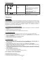
8. PC Interface Control User Manual
This section shows how to connect:
A single power supply via RS-232 Interface
2 or above(up to 31) power supplies via RS-485 Interface
-10-
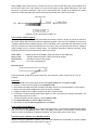
8.1 Connect a Single Power Supply to PC via RS-232
The power supply can be connected to PC via RS-232 as shown in Figure 8.1. Please use the
provided RS-232 connection cable. The data format is ASCII, no parity bit, 8 data bit, 1 stop bit. The
recommended baud rate is 9600 bps.(Please refer to Appendix B for details)
Connect the RS-232 cable to the
RS-232 port at rear panel of the
Power Supply
RS-232
10m max.
Figure 8.1 Connection between a PC and a Single Power Supply via RS-232.
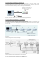
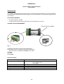
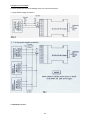
8.2. Connect Multiple Power Supplies to PC via RS-485
For multiple power supplies, use the RS-485 Interface through the RS-485 port at the rear panel of the
power supply. Up to 31 power supplies can be connected via RS-485.
You will need a RS-232 to RS-485 adapter (optional accessory) and the connection shown in Figure
8.2a and 8.2b.
Figure 8.2b
Connection diagram for multiple power supply.
Figure 8.2a
Connection diagram between Adapter and RS-485 connectors.
For more information, please see Appendix B and Appendix C.
-11-
8.3. PC Application Software
8.3.1. What the Application Software will Do
The application software can perform:
* Timed Programming;
* Preset Programming;
* Data Logging;
* Voltage, Current and Upper Voltage Limit Settings.
8.3.2. System Requirements
* CPU 450 MHz or above
* 128 MB Ram
* Min. monitor screen resolution: 800 x 600 pixels.
* Operating systems: Windows XP, ME, 2000, 98SE, 98
All brand or trade names are trademarks or registered trademarks of their respective
companies.
8.3.3. Installation of Software
1. Place the provided installation disc in your CD Rom Drive and run setup.exe.
2. Follow the instructions in the setup program.
NOTE
During the running of the setup program, you may encounter "VERSION CONFICT" remarks, ignore it
and click "YES" to complete the installation.
3. A SDP icon is created in the Program Menu.
8.4. Running the application software for RS-232 Interface
NOTE
Before running the application software, you must have installed and connected your power supply to
the PC using the provided RS-232 cable.
8.4.1. Start-up the Application Software for RS-232
1. Ensure your PC is OFF, connect RS-232 cable to the serial port of your PC and the power supply.
2. On your power supply, press the [SHIFT] key, then quickly press [RS232/485] key and select RS232 followed by [ENTER] key.
3. Switch on your PC and run the SDP program.
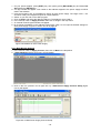
4. Click on Setup, and select the desired COM Port. The default is set at COM 1.
Fig. 8.4.1a.
5. Click on Supply Connect, then click on Single in the drop menu.
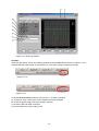
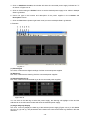
6. An 'Internal Timed Program" Window will appear as shown in Figure 8.4.1b. Click on the Data Log
header on top right and a Data Log Window as shown in Figure 8.4.1c will appear.
Fig. 8.4.1b. Internal Timed Program Header
-12-
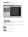
Figure 8.4.1c Data Log Window
Remarks:
When the right bottom corner of the display window shows the UVL value as shows in Figure 8.4.1d, it
indicated that the power supply is connected to PC. The power supply is operating normally.
Figure 8.4.1d
Figure 8.4.1e
If it shows No Connection as shown in Figure 8.4.1e, check the following:
A) Go back to Setup, check if the correct COM port has been assigned.
B) Check the power supply if RS-232 has been selected.
C) Check the RS-232 cable connection.
D) Check whether the power supply is ON.
-13-
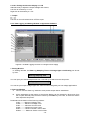
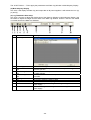
8.4.2. General Operations
Please refer to Figure 8.4.2a for the following descriptions.
Figure 8.4.2.
1. Power Supply Description:
Serial-No. S2405000
You may click on the assign an identification for your power supply in use. Actually this feature is ainly
for multiple power supplies application with RS-485.
2. Address:
This function is for multiple power supplies application. Each power supply has a unique address.
Ignore this function when using RS-232.
3. Voltage:
##.# V
Enter the desired output voltage with decimal point.
4. Current:
#.## A
Enter the desired current limit with decimal point.
-14-
5. and 6. Voltage and Current display on LCD
Alternative way to adjust the Output Voltage and Current,
Left click to increase by 0.1 unit;
Right click to decrease by 0.1 unit.
7. Output
Left click on icon will switch ON or OFF the ouput.
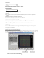
8.4.3. Data Logging and Setting Window in Application Software
Figure 8.4.3a Data Logging Function for a Single Power Supply
1. Setting Window
In "Setting" Window, the Data Log Sampling Time and Voltage Upper Limit Setting can be set
by User.
Data log Sampling Time
You can input your desired sample time from 1 second up or select from the drop menu.
Voltage Upper Limit Setting
You can set your output voltage upper limit value to further safeguard your low voltage applications.
2. Data Log Window
A. You can use the "Data Log" window to view present output data or stored data.
B.
All the parameters at the bottom of the window display can be changed by direct entry from
the PC (with decimal point) and then confirm by the Enter key of the PC, or select the values
from respective drop menu.
Parameters at the bottom of the Data Log window:
V Min -------- Minimum Voltage Level.
V Max.-------- Maximum Voltage Level.
C Min. -------- Minimum Current Level.
C Max. -------- Maximum Current Level.
W Min. -------- Minimum Power Level in Watt.
W Max. -------- Maximum Power Level in Watt.
-15-
3. Log Name
Click cursor on "Untitle", and type in a name for your log.
4. Log Description
You can type in your detail description of your log.
5. Save Log
a) This function (and the icon) becomes effective when a Log Name is entered to replace the
"Untitle".
b) Click on it will save the current data onto the PC.
c) To retrieve the data, go to the drop menu at (3) Log Name.
6. Export to a File of MS Excel "xls" type
Click on this icon will export the collected data (in the Save Log) in "xls" format to your PC.
7. Open File Log of "xls type"
Click on this icon will import the collected data in .xls format file to the SDP software.
8. Delete Log
Click on this icon will delete the current log or retrieved log on the display at a current Log Name.
9. Print Log in "xls" Format
8.4.4. The Time Frame Concept of Data Log
The data logging function starts when the software is started running. In figure 8.4.4a, it shows the
data log in graphical presentation. The Time Minimum and Time Length can be set by Users. Both
parameters are adjustable so that any time period of the log can be displayed for analysis.
Figure 8.4.4a. The Data Log Window Display
-16-
When T Min is set to zero second, it means the unit is on real time and the length of time lapsed is on
the left hand side of the Time Minimum. T Len is the length of time lapsed starting from the Time
Minimum. In the above example, T Min is set to 320 second and T length to 60 second, the display
shows the output data starting at 320 seconds ago and ending at the 380 second mark.
Figure 8.4.4b The time frame of Data Log
8.4.5. Internal Timed Program
The PC Interface remote mode really eliminates the tedious process in keying in groups of entries on
the power supply. Because all the data are displayed together in the monitor, possibility of wrong entry
is greatly reduced. Data of different groups can be classified, stored, exported and retrieved for use at
any time. Furthermore, retrieved data will be in red colour if they exceed the preset limits of voltage in
Upper Voltage Level or Current Limiting values. The operation principle of Saving, Exporting, Filing,
Deleting and Printing are the same as the Data Log Function.
Clear Table........... Delete all data in the Display Table and ready for new data entry.
Save To PS..............Transfer data from Display Table to the Power Supply.
Read Fro PS............Get data from the Power Supply.
Run.........................To run the Timed Program
Running Cycle
Enter the number of desired running cycles here. The maximum cycles is infinite as "0" cycle is
entered.
Operation
1. Clear old data in the power supply by first click [Clear Table] then click [Save To PS].
2. Check if no data in power supply by click [Read Fro PS].
3. Enter data in the table using the 'Up Down Left Right' keys of your PC keyboard for new locations
4. Data exceed the rated voltage and current will not be accepted.
5. Voltage exceed set UVL (Upper Voltage Limit) will not be accepted.
6. If retrieved or entered data exceed preset Upper or Lower Limit setting of voltage/ current/time, the
data will becomes red in colour.
7. Transfer set data to power supply by clicking [Save to PS].
8. Click [Read Fro PS] to initiate the [Run] Command.
9. Set number of desired [Running Cycle] and click [Run].
8.4.6. Internal Preset Memory
The operation principle is the same as Internal Timed Program. To activate the selected preset values,
click on the box of the [Select] column then click [Run]. If retrieved or entered data exceed present
Upper or Lower Limit Setting of voltage/current/time, the colour will become red in colour.
8.5. Running the software using RS-485 Interface
Note
Before running the application software, you must have installed and connected your power supplies
to the PC via RS-485 as Figure 8.2a and b on page 16.
-17-
1. On your power supplies, press [SHIFT] key, then quickly press [RS-232/485] key and select RS485 followed by [ENTER] key.
2. A 3-digit number will appear. This number is the address asigned to the power supply ad will be
used in the software.
3. Using the keypad to key in the address to assign for each power supply. The range is 001 ~ 031
and each of the power supplies requires an unique address.
4. Switch on your PC and run the SDP program.
5. Click on Setup, and select the desired COM port. The default is set to COM 1.
6. In the tool bar, Click on Supply Connect, then click on Single in the drop menu.
7. An Internal Timed Program Window will appear.
8. By choosing the address in the Address Field (Figure 8.5a) You can input the desired settings for
each power supply as given in Section 8.4.2a on page 20.
Figure 8.5a Address of each Power Supply.
8.5.1. Multi Window Analysis
1. In the tool bar, Click on Supply Connect, then click on Multi in the drop Menu.
2. A Multi Windows Window (Figure 8.5.1a) will appear.
Figure 8.5.1a Multi Window
3. Click on the icon (circled in red in figure 8.5.1a), a Multi Power Supply Connect Setup (Figure
8.5.1b) will appear.
Figure 8.5.1b Multi Power Supply Connect Setup.
-18-
4. Click on AutoScan Connect, the window will show the connected power supply indicated as "Y"
as shown in Figure 8.5.1b.
5. Click on the box along the Visible Column to set the desired power supply to be visible in Multiple
Data Log Window.
6. Users can type in the location and description of the power supplies in the Location and
Description Column.
7. Click on Close button (bottom right hand corner) to return to Multiple Data Log Window.
8. Remarks:
Fig 8.5.1c
(1) Show Digital
One click, it will show the digital readings of all the connected power supplies
(2) Show Log
One click, it will show the data log of all the connected power supplies.
(3) Show Digital and Log
One click, it will show both the data log of all the connected power supplies.
Figure 8.5.1d
You can click on the data log to select the power supply, the data log will highlight in blue and the
address bar in the left bottom window will show the selected power supply.
(3) Single Alleyway Display
One click, it will only display the data log of the selected power supply (Figure 8.5.1e). It will disable
the icon (2), (3) and (4). The parameters at the bottom are same as the Data Log Window in RS-232
Interface.
-19-
The All SP Tick box --- Tick to apply the parameters to all Data Log Window in Multi Alleyway Display.
(4) Multi Alleyway Display
One click, it will display the Data Log and output data of all power supplies. It will activate the icon (2),
(3) and (4).
(5) Log Thumbnails Size Setup
One click, it let user to adjust the window size of the Data log Window in Multi Alleyway Display. Use
the sliders to adjust the height and the width of the Data Log Window. Scale 4:3 tick box can enable
4:3 screen size for the Data Log Windows.
1.
2.
3.
4.
5.
6.
7.
8.
9.
Icon
Save Log
Description
Delete Log
Export to a file of xlstype
Open file Log of xlstype
Close file Log of xlstype
Print Log
Log
Sample
Set V
It can delete the log data in the PC
Click on this icon will export the collected data (in Data Log) in xls
format to your PC.
Click on this icon will import the collected data in xls format file to
the SDP software.
Click on this icon will close the import xls
format file.
Print Log in xls format.
Click on it to select the save log data.
Click on it to select the sampling time.
Click on it and type in to change the voltage setting of the selected
power supply.
Click on it and type in to change the current setting of the selected
power supply.
10. Set C
-20-
APPENDIX A
COMMAND SET
Remarks in using the Remote Programming Mode
The RS-232/485 interface is always ready for connection to PC for remote programming operation.
The default setting is RS-232, however it is recommended to check the status of RS-232/485 setting
by using the keypad at the front-panel (see 6.1.3.)
The keypad can be disabled by: either pressing
command SESS <address> <CR>.
SHIFT
then
LOCK/UNLOCK
or by entering the input
Command Set
{ }-command data, [ ] – return data, [OK] = "OK", [CR] = 0 dh
???? = 30h, 30h, 30h, 30h - 39h, 39h, 39h, 39h (4 bytes data)
??? = 30h, 30h, 30h – 39h, 39h, 39h (3 bytes data)
?? = 30h, 30h – 39h, 39h (2 bytes data)
<address> 30h, 30h – 3fh, 3fh (2 bytes data)
Bold – Input Command
Italic – Return Data from Power Supply
PS = Power Supply
Command Code & Return Data
Input Command:
SESS <address> <CR>
Description
Disable front panel keypad and
make PS to Remote Mode
Return Data from Power Supply:
[OK] [CR]
Input Command:
ENDS <address> <CR>
Enable front panel keypad and
make PS to exit Remote Mode
Return Data from Power Supply:
[OK] [CR]
Input Command:
CCOM <address> <RS> {000-255} <CR>
Change RS232/RS485
<RS> = 0 -> RS232
<RS> = 1 -> RS485
Return Data from Power Supply:
[OK] [CR]
Input Command:
GCOM <address> <CR>
Return Data from Power Supply:
Get the RS-485 address
[RS] RS485 Address [??] [CR]
[OK] [CR]
Input Command:
GMAX <address> <CR>
Get maximum voltage and
current of PS
Return Data from Power Supply:
Voltage [???] Current [???] [CR]
[OK] [CR]
-21-
Command Code & Return Data
Input Command:
GOVP <address> <CR>
Description
Get Upper Voltage
Limit of PS
Return Data from Power Supply:
Voltage [???] [CR]
[OK] [CR]
Input Command:
GETD <address> <CR>
Return Data from Power Supply:
Voltage [????] Current [????] [0] [CR]
[OK] [CR]
Voltage [????] Current [????] [1] [CR]
[OK] [CR]
Input Command:
GETS <address> <CR>
Get Voltage & Current reading
from PS
PS in CV mode
PS in CC mode
Get Voltage & Current Set
Value from PS
Return Data from Power Supply:
Voltage [???] Current [???] [CR]
[OK] [CR]
Input Command:
GETM <address> <CR>
Get All Preset
Memory Values from PS
Return Data from Power Supply:
Memory 1 Voltage [???] Current [???] [CR]
Memory 2 Voltage [???] Current [???] [CR]
.
.
.
.
.
.
.
.
.
.
.
.
.
.
.
Memory 9 Voltage [???] Current [???] [CR]
[OK] [CR]
Input Command:
GETM <address> location {1-9} <CR>
Return Data from Power Supply:
Get Memory from
Specific Preset of
PS
Voltage [???] Current [???] [CR]
[OK] [CR]
Input Command:
GETP <address> <CR>
Return Data from Power Supply:
Get all the Timed
Program Memory of
PS
Program 00 Voltage [???] Current [???] Minute [??] Second [??] [CR]
Program 01 Voltage [???] Current [???] Minute [??] Second [??] [CR]
.
.
.
.
.
.
.
.
.
.
.
.
.
.
.
.
.
.
.
.
.
Program 19 Voltage [???] Current [???] Minute [??] Second [??] [CR]
[OK] [CR]
Input Command:
Get Timed Program Memory
GETP <address> program {00-19} <CR>
from Specific Program of PS
Return Data from Power Supply:
Voltage [???] Current [???] Minute [??] Second [??] [CR]
[OK] [CR]
-22-
Command Code & Return Data
Input Command:
GPAL <address> [CR]
Description
Get LCD Display
Information
Return Data from Power Supply:
Reading voltage [####] V [ON]
Reading current [####] A [ON]
Reading watt [####] W [ON]
Timer minute [####] second [##] timer [ON] colon [ON] m [ON] s [ON]
Setting voltage [###] V-const [ON] V-bar [ON] V [ON]
Setting current [###] I-Const [ON] I-bar [ON] A [ON]
Program [#] Program [ON] P-bar [ON]
SETTING [ON] Key lock [ON] Key open [ON] FAULT [ON] Output on
[ON]
Output off [ON] Remote [ON] [CR]
[OK] [CR]
Input Command:
Set Voltage Level
XXX-Max. Output Rating
VOLT <address> voltage {000-XXX} <CR>
Return Data from Power Supply:
Voltage = XX.X V
Current = X.XX V
[OK] [CR]
Input Command:
Set Current Level
CURR <address> current {000-XXX} <CR>
Return Data from Power Supply:
[OK] [CR]
Input Command:
SOVP <address> voltage {000-XXX} <CR>
Set upper Voltage Limit of PS
Return Data from Power Supply:
[OK] [CR]
Input Command:
SOUT <address> 1 <CR>
Disable Output of PS
Return Data from Power Supply:
[OK] [CR]
Input Command:
SOUT <address> 0 <CR>
Enable Output of PS
Return Data from Power Supply:
[OK] [CR]
Input Command:
POWW <address> location {1-9}0 <CR>
Enable the output when switch
on the power supply.
Return Data from Power Supply:
[OK] [CR]
Input Command:
POWW <address> location {1-9}1 <CR>
Disable the output when switch
on the power supply.
Return Data from Power Supply:
[OK] [CR]
Input Command:
PROM <address> location {1-9} Voltage {000-XXX} Current {000XXX} <CR>
Return Data from Power Supply:
[OK] [CR]
-23-
Set Voltage and Current
values of Preset
Memory
Command Code & Return Data
Input Command:
PROP <address> location {00-19} Voltage {000-XXX} Current
{000-XXX} Minute
{00-99} Second {00-59} <CR>
Description
Set Voltage, Current and
Time period of Timed
Program
Return Data from Power Supply:
[OK] [CR]
Input Command:
RUNM <address> location {1-9} <CR>
Recall Preset Memory 1-9
Return Data from Power Supply:
[OK] [CR]
Input Command:
RUNP <address> times {000-999} <CR>
Run Timed Program
(000 = run infinite times)
Return Data from Power Supply:
[OK] [CR]
Input Command:
STOP <address> <CR>
Stop Timed Program
Return Data from Power Supply:
[OK] [CR]
-24-
APPENDIX B
RS-232 CABLE AND CONNECTION INFORMATION
APPENDIX B RS-232 CABLE AND CONNECTORS INFORMATION
Remark
- The line buffer is assumed to be 16 bytes long.
- The serial asynchronous framing format: no parity bit ,8 data bit, 1 stop bit & bit rate: 9600 bps
-25-
APPENDIX C
Optional RS-232 to RS-485 Adapter
User manual
INTRODUCTION
This adapter is designed for connecting your PC with RS-232 communication port to HALF-DUPLEX
RS-485 interface programmable power supplies (or other equipment). Its transmission length can be
up to 1000 m.
FEATURES & BENEFITS
*
*
No driver software is needed
Can directly be connected to male RS-232 communication port of your PC
CONTROL AND PIN ASSIGNMENT
RS-232 to RS-485 Adapter
(2)
(3)
(4)
(5)
(1)
Fig. 1
(1) RS-232 (Connect to the PC communication port)
(2) RS-485 (Connect to equipment with RS-485 interface)
There are 6 pins, only A+, B- and GND pin are useful.
(3) Pin A+
(4) Pin B(5) Pin GND
SPECIFICATIONS
RS-232 side of the adapter
RS-485 side of the adapter
Connection Speed
Transmission Length
Dimensions
Weight
DB-9 female connector
3-pin connector – Pin 1: RS-485 (+A)
Pin 2: RS-485 (-B)
Pin 3: GND
9600 bps
Up to 1000 m
(WxHxD) 33 x 17 x 87 mm
40 g
-26-
CONNECTION DIAGRAM
Connect the RS-232 side of the adapter to the PC Communication port.
1. Single Power Supply Connection:
© PeakTech® 02/2005
-27-