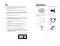
1
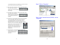
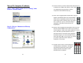
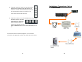
Ethernet Control Box
for SE-800
RMC-120
Error!
USER MANUAL
Http://www.datavideo-tek.com
2005/2/18
Warnings and Precautions
1. Read all of these warnings and save them for later reference.
2. Follow all warnings and instructions marked on this unit.
3. Unplug this unit from the wall outlet before cleaning. Do not
use liquid or aerosol cleaners. Use a damp cloth for cleaning.
4. Do not use this unit in or near water.
Service and Support
It is our goal to make your products ownership a satisfying
experience. Our supporting staff is available to assist you in
setting up and operating your system. Please refer to our web site
www.datavideo-tek.com for answers to common questions,
support requests or contact your local office below.
5. Do not place this unit on an unstable cart, stand, or table. The
unit may fall, causing serious damage.
6. Slots and openings on the cabinet top, back, and bottom are
provided for ventilation. To ensure safe and reliable operation
of this unit, and to protect it from overheating, do not block or
cover these openings. Do not place this unit on a bed, sofa,
rug, or similar surface, as the ventilation openings on the
bottom of the cabinet will be blocked. This unit should never
be placed near or over a heat register or radiator. This unit
should not be placed in a built-in installation unless proper
ventilation is provided.
7. This product should only be operated from the type of power
source indicated on the marking label of the AC adapter. If
you are not sure of the type of power available, consult your
Datavideo dealer or your local power company.
8. Do not allow anything to rest on the power cord. Do not locate
this unit where the power cord will be walked on, rolled over,
Datavideo Corporation (USA)
12300-U East Washington Blvd., Whittier, CA 90606 USA
Tel: +1 562 696 2324
www.datavideo.us
Datavideo Technologies Europe BV
Californiedreef 263565 BL Utrecht, The Netherlands
Tel: +31 30 261 9656
www.datavideo.info
Datavideo UK Limited
Unit 2 Waterside Business Park, Hadfield, Glossop, Derbyshire SK131BE
Tel: +44 1457 851000
www.datavideo.info
Datavideo Technologies Co., Ltd.
10F, 176 Jian-Yi Rd, Chung Ho City, Taipei Hsien, Taiwan 235
Tel: +886 2 8227 2888
www.datavideo.com.tw
Datavideo Technologies China Co.
2F-D, 2 Lane 777, West Guangzhong Rd, Zhabei District, Shanghai
Tel: +86 21 5603 6599
www.datavideo.cn
Datavideo Technologies (S) PTE Ltd.
100 Lor 23, Geylang Rd, #01-03 D’Centennial, Singapore 388398
Tel: +65 6749 6866
www.datavideo.sg
or otherwise stressed.
9. If an extension cord must be used with this unit, make sure
that the total of the ampere ratings on the products plugged
into the extension cord do not exceed the extension cord’s
rating.
10. Make sure that the total amperes of all the units that are
plugged into a single wall outlet do not exceed 15 amperes.
1
All the trademarks are the properties of their respective owners.
Datavideo Technologies Co., Ltd. All rights reserved 2005.
26
P/N: 082060376E1
11. Never push objects of any kind into this unit through the
cabinet ventilation slots, as they may touch dangerous voltage
points or short out parts that could result in risk of fire or
electric shock. Never spill liquid of any kind onto or into this
unit.
12. Except as specifically explained elsewhere in this manual, do
Specifications
not attempt to service this product yourself. Opening or
removing covers that are marked “Do Not Remove” may
RS-232 Data Control Port
expose you to dangerous voltage points or other risks, and
Connecting Datavideo SE-800 RS-232 Remote Control Port
will void your warranty. Refer all service issues to qualified
service personnel.
RJ-45 Ethernet Port
13. Unplug this product from the wall outlet and refer to qualified
Connecting PC or Laptop Ethernet Port for Remote Trigger
Control
service personnel under the following conditions:
a. When the power cord is damaged or frayed;
b. When liquid has spilled into the unit;
Dimensions W x D x H
c.
100m/m x 67m/m x 23m/m
d. When the product does not operate normally under
When the product has been exposed to rain or water;
normal operating conditions. Adjust only those
Weight
controls that are covered by the operating instructions
0.12 Kg
in this manual; improper adjustment of other controls
may result in damage to the unit and may often
Power
require extensive work by a qualified technician to
Input: DC 9V/0.1A
restore the unit to normal operation;
e. When the product has been dropped or the cabinet
Accessories
has been damaged;
AC/DC Power Adapter
f.
1.2M RS-232 Cable x 1
When the product exhibits a distinct change in
performance, indicating a need for service.
1.2M RJ45 Ethernet Cable x 1
Instruction Manual
Installation CD
25
2
Table of Contents
Warnings and Precautions …... …... …... …... …... …... …... …..1
Warnings and Precautions
What's in the Box……………..……….……………………...……….4
Introduction……………………………………...……………..………5
Introduction
Product overview
A: For the ROM B, please make sure all the video effects and
transition effects have turned off. Then, press up key and
check the check the digital number which shows on
“EFFECT” and “SPEED” if it’s showing 2.4 as below.
EFFECT
SPEED
Features…………………………………………………..….………...6
02 4
User Interface Functions……………………………..……….……...7
Installation, Connections, Set up…………………………..……....14
Connections
PC IP setting
RMC-120 IP setting
SE-800 IP setting
Troubleshooting…………………….…………..…………...……….22
No connection
FAQ……………………………………………..………..….………..23
Specification…………..………………………..………..….………..25
Technical Support...…………………………………….……………26
3
24
FAQ
What’s in the box?
1. Q: When I select BACKGROUND, the “ON” button starts
blinking. Sometimes it will speed up, but sometimes it will
slow down. Is it normal?
1. RMC-120
2. AC / DC Power Adaptor * 1
3. RJ45 Ethernet cable 1M * 1
4. RS-232 cable 1.2M * 1
A: Yes, it’s normal, and it will not affect the performance.
2. Q: When I use GPI control, occasionally the “PLAY” key will
turn on in SE-800 switcher. Why the remote interface doesn’t
turn on?
A: It’s normal. Don’t need to worry.
(cross over)
3. Q: While programming the function keys is in process, three
seconds after I pressed “ENT” key, the remote interface will
display number “555”. Is that normal?
A: We already notice this problem, and will fix it in next
version software.
4. Q: Are all SE-800 can be controlled by RMC-120?
5. User manual
6. Installation CD
A: No. RMC-120 can only use with SE-800 ROM A: v5.6;
ROM B: v2.4, or later version firmware.
5. Q: How do I check my SE-800 firmware version?
A: For the ROM A, when SE-800 turns on, please check the
digital number which shows on “EFFECT” and “SPEED” if
it’s showing 5.6 as below.
EFFECT
SPEED
05 6
23
4
Trouble shooting
Introduction
Thank you for purchasing Datavideo’s RMC-120. The RMC-
1. “Connect failed” error message.
120 is an SE-800 accessory, which can be used to remotely
control the SE-800 via RS-232 commands with a simple, but
unique operator control interface. You will be amazed and
pleased at what you can do with this advanced piece of
technology. In order to bring out the maximum performance
of this unit, we recommend that you spend some time reading
this manual carefully.
Product Overview
The RMC-120 is designed to control the SE-800 via Ethernet.
Now you can remotely control shots, mixes, and edits, all
within the SE-800 RS-232 protocol. The RMC-120 is a simple
RJ45 to RS-232 device, featuring powerful software that
allows you to use your PC or laptop as a control center.
What is the benefit of using an RMC-120? For example, you
could use it in remote areas, where you might be far away
Please check your PC Computer IP address
settings again, and be sure it has been set up
properly.
IP address: 192.168.0.1
Subnet mask: 255.255.255.0
RMC-120 IP address settings assigned Condition
from your switcher, as long as you have an Internet
connection you can always be in control.
The full size control panel includes most control functions of
Setting the Local IP: 192.168.0.7
Setting the Subnet Mask : 255.255.255.0
Setting the Remote IP: 192.168.0.1
the SE-800, which includes video selection, audio selection,
video effects, transition effects, color corrections and RGB
corrections. Also, it includes 30 user programmable macro
function keys that let you play back preset transitions and
effects instantly by clicking a single button.
5
SE-800 PC Control Software IP address settings
assigned Condition
Client Mode setting Remote IP 192.168.0.7
22
Step 3: Select “Client Mode” and set up Remote IP
192.168.0.7 then Click on the “OK” button
Features
Standard RJ 45 and RS-232 connectors
Easy to install
Simple connection
Full function remote control
Friendly user interface
21
6
Set up SE-800 IP address
User Interface Functions
1
2
3
4
5
6
Step 1: Click on the SE800 icon
7
8
9
10
23
22
11
21
1.
20 19 18
17 16 15
14
13
Step 2: Right Click on the mouse button and select
“Options”
12
Joy stick and mode selector
13. T-Bar
14. Main video source selectors
2.
Voice sync adjustment
3.
Video input format selector
15. Sub video source selectors
4.
Audio channel selectors
16. Chroma key control
5.
Audio follow video switch
17. Preset Banks F1 to F30
18. Video effects: Picture in Picture
6.
Color processor
7.
Border control
19. Video effects: Paint controls
8.
Background control
20. Video effects: Mosaic controls
9.
Transition source selectors
21. Numeric Keypad
10. GPI function on/off button
22. Transition effects.
11. Play F1 to F30 by sequence
23. Audio channel selectors
12. Take function key
7
20
Step 4: Setting the Local IP: 192.168.0.7
Setting the Subnet Mask : 255.255.255.0
Setting the Remote IP: 192.168.0.1
Setting the Baud Rate: 57600
Setting the Data Bit: 8
Setting the Stop Bit: 1
Setting the Parity: Odd
Select TCP Misc Mode and Click on the
Write Button, and then Exit Button
1. Joystick and Joystick mode selector: The Joystick control
can function either in RGB Color Correction mode or
Position Control mode, depending on the position of the
selector below it. In RGB Correction mode, you can make
real time RGB white balance corrections to the Main
Source video. This function (white balance adjustment) is
effective only with “Input Format selection” mode. In
Position Control mode, the joystick
is used to position the selected
effect (Mosaic or Picture In Picture)
anywhere on the screen in real time.
2. Voice Sync: adjusts for audio delay
or advance from –19 to +3 frames
for the Audio Input that is fed from
the selected Video channel.
3. Input Format selectors: These buttons allow you to select
the input video format for each channel. To operate, press
the upper button to select the channel (each press cycles
the LED to the next channel), then
press the lower button to select the
proper format. Disengage the
selectors by pressing a button in
any other section on the front panel.
4. Audio Input Selectors: Controls which audio input channel
(A, B, C, and/or D) is sent to the Audio Bus “Video”
channel in SE-800. The row of selector buttons across the
top of this section have LEDs to show which input channel
is active. If the A+V function (5.) is
engaged, the source channel
19
8
selected on the Main Source bus is automatically selected.
If A+V is not engaged, the input source is user selectable.
Level controls for each input source are the rotary pots
Set up RMC-120 IP address
Step 1: Double click or Config Icon
below the selection buttons.
5. A+V: Audio follow video switch. When this button is
engaged (you’ll know it is engaged because the LED is lit),
the audio associated with a selected input source
automatically follows the video through the
Step 2: Click on the Search Button
dissolve. When the button is inactive, audio
must be switched manually.
6. Color Processor: These controls become active in
conjunction with the Input Format selector (3.). When that
control is active, you can make adjustments to the
selected channel’s brightness, contrast, color, and tint
(NTSC only) by pressing the up and down arrow buttons.
The LEDs on the left side of this section indicate relative
steps above or below unity (the signal exits the control
unchanged). Press and hold the Reset button in the upper
right for 2 seconds or more to reset the Color Processor
Step 3: Click on the MAC List
controls all to unity.
The “Reset All”
button resets the
color correction and
RGB correction
settings for all 4
inputs.
9
18
Step 5: Set up IP address and Subnet mask.
IP address: 192.168.0.1
Subnet mask: 255.255.255.0
7. Border: controls the border style and color for the Picture
in Picture effect. This control is accessible when the
Picture in Picture controls,
Wipe and Zoom effects. (22.)
are engaged.
8. Background: when Background is selected in either the
Main or Sub Video Source (14, 15.), and the ON button is
pressed (and the LED is lit), repeated
presses of the color button cycle
through the 8 possible solid
backgrounds.
9. Video or Audio: selects the T-Bar operating mode of the
SE-800, between Video (default). (Audio mode is not
working at this moment.)
10. GPI (General Purpose
Interface) function: ON/OFF,
allow RMC-90 to trigger
other GPI devices.
11. PLAY: Play memorized
function key from F1 to F30
in sequence.
12. TAKE: Switch the video or audio source setting from one
to another.
13. T-Bar: used to manually perform a transition.
Note: Before you turn off the interface/software on your PC, please
make sure the T-Bar is on either Top or Bottom position. Otherwise, it
17
10
may cause SE-800 crash. When it happened, you could disconnect 9pin
Step 3: Click on “Properties”
RS-232 cable from SE-800 to resolve this problem.
14. Main Video Source Selector: used to select which of the
four video input channels or
background is sent to the Main
video output.
15. Sub Video Source Selector: used to select which of the
four video input channels or
background will be transitioned
to or used as a sub source in
an effect.
16. Chroma Key: when engaged, this removes the selected
Step 4: Select “Internet Protocol (TCP/IP)”, click on
“Properties”
color from the Main Video Source and reveals the
corresponding portions of the Sub Video Source.
Repeated presses of the Color up and down buttons
selects the color to be removed. Repeated
presses of the Level up and down buttons
sets how much of the color will be
removed. Color and level information are
displayed in the windows above the
Keypad (21.)
17. Preset selectors: control the 30 user programmable
preset locations for storing
customized effects and
transitions.
11
16
Set up PC Computer IP address
Step 1: Click “Start” button. Go to “Setting”, then
click on “Control Panel”
18. Picture in Picture: puts the selected Sub Video Source in
a window on the Main Video Source, with control
over window size and placement. Used in
conjunction with the Border keys (7.)
19. Paint: when engaged (and the Paint LED is lit), this
applies a posterized effect to the selected Main
Video Source. Repeated presses of the up and
down buttons set the intensity level of the effect,
from 1 (least) to 4 (most). The level setting is
displayed in the Effects window above the
Keypad (21.).
Step 2: Click on “Network and Dial-up
Connections”
20. Mosaic: when engaged (and the Mosaic LED is lit), this
turns the selected Main Source Video into a mosaic of
colored squares. There are 8 mosaic patterns to choose
from, selected by repeated presses of the up
and down buttons. The effect can be applied to
the whole image or one of two window sizes by
select PIP effect (18.) You can also use Joystick
(1.) mode to place the mosaic window in
anywhere on the screen.
21. Keypad: used to enter numerical data that
controls effects or transitions. The Effects
and Speed windows above the Keypad
display parameter information for the
selected effect or transition.
15
12
22. Transition selectors: These five selection buttons
determine the transition type and allow for the
Installation, Connections, Set up
Connections
selection of certain effects that are performed on
the selected Main Video Input channel. The
RS-232
Take-button executes an auto play.
SE-800 Real Panel
23. Audio Bus selectors: the LEDs indicate which of the audio
inputs are active in the Main
audio output mix. Press the
button to either include or
exclude the channel. The left
button, labeled Mic/Aux, can be set to either Mic, Aux, or
off.
RS-232
Cable
RMC-120
Ethernet
HUB
Above all are basic functions descriptions. For more detail
information and application, please refer to SE-800 user manual.
Ethernet Cable
Computer Real
Panel
13
14