1
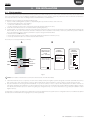
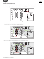
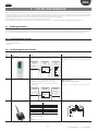
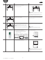
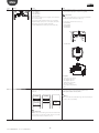
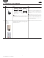
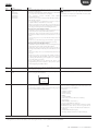
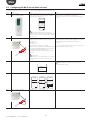
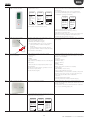
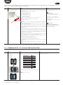
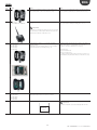
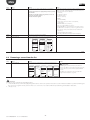
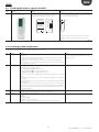
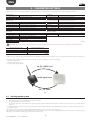
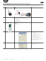
ENG 4.9 Checking the wireless signal in the field Step Device rTM SE handheld CAREL code WS01L01M00 Action The rTM SE handheld can be used to check the quality of the wireless signal directly where the sensors are to be installed.Run the following functions: =+$1'+(/' =%&$5(/ 1RGH -RLQHG &KDQQHO 3DQ[% [($) '( !3LQJ7HVW !&RPPDQGV !/HDYH1HW Notes The display shows the wireless signal levels of the Router and the Access Point (highlighted by “*”), identified by the MAC address shown on the product label. (1(5*< 3LQJ7HVW 1RGHV 0$&$5VVL )$ () ( 3UHVV min WRHVF max signal During this stage, the rTM SE handheld receives a wireless message from all the Routers within range at regular 3 s intervals. Tab. 4.h 4.10 Checking system configuration During the binding stage, the number of units connected can be checked by connecting the PVPRO or PWPRO supervisor to the Access Point and configuring the system (either before or after installation of the devices). Step 1-SV Device Supervisor 2-SV Supervisor Action Connect the supervisor to the Access Point Check that: • for each Access Point the number of units connected corresponds to the total number the sensors bound to the device; • all the sensors are Online. If some sensors are not online, try stimulating the switch on the sensor to make sure data transmission occurs correctly, or wait the set data transmission time. Notes Wait for the sensor transmission time to elapse to see the temperature value displayed on the supervisor screen. Configure the sensors with the required parameters E.g.. for EP SE sensor and Router-sensor: HR_01 TRANSM_CYCLE Transmission time LO_TEMP_TRESHOLD Min. temp. alarm threshold HI_TEMP_TRESHOLD Max. temp. alarm threshold The EP SE sensors measure 2 temperatures, and the same parameters also apply to NTC 2. To disable the probes that are not used, set parameters EN_NTC_1 and EN_NTC_2 accordingly. To enable or disable the door and defrost inputs, set parameters EN_DI_DOOR and EN_DI_DEFROST. For installations with more than one Access Point in the same environment, make sure there are no devices that have the same channel, PANID and extended PANID. In the rare event that this is true, make the necessary changes (Reset the device and reassign the network). 3-SV Router 4-SV Supervisor Check the Router serial addresses, adding the corresponding serial address to the installation data table. Also mark these on the layout drawing Print out the Access Point parameters: • channel; • PANID; • extended PANID; • number of devices connected. Keep the print outs together with the installation data and layout drawings. Tab. 4.i 23 rtM +0400030EN - rel. 1.2 - 04.04.2013