1
ENG
14. TROUBLESHOOTING
Problem
Possible causes
Checks
Can’t see the Access Point on the
supervisor
Incorrect communication parameter settings
LED L1 is flashing slowly (1s) check the following points on
Access Point and supervisor:
• serial address;
• communication speed (9600/19200);
• RS485 serial electrical connections;
• serial port settings on the supervisor; make sure the right
port is set and the connection settings are OK.
Can’t see the sensor on the supervisor
Wrong model on supervisor
Make sure that the right model has been loaded on the
supervisor;
No communication due to:
binding not completed correctly;
excessive distance;
battery discharged;
different serial address assigned during
commissioning;
• make sure the insulating protection has
been removed from the battery;
• check power supply to the Access Point and
Routers.
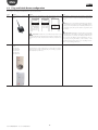
Stimulating the sensor L1 remains on for 20 s and then goes
off. Repeat the binding procedure,
Stimulate the sensor checking that there is communication
and that the Access Point receives the data.
Check the low battery alarm sent to the supervisor.
Check communication with the Access Point.
Remove the protection from the battery.
If necessary, power the Access Point and Routers using a UPS.
Sensor with low wireless signal level
Excessive distance between sensors and Access
Point and Routers. Check that the environmental conditions have not changed (e.g. cabinets,
shelves, partitions, different position of the
sensor).
Place a Router in the network between the sensor and the
Router/Access Point. Check the quality of the signal using
the Router-Sniffer, or alternatively move one of the Routers
already installed;
Sensor not bound to the right wireless
network
Binding has been performed when another wi- Stimulate the sensor to make sure that it communicates with
reless network was open or the minimum time its Access Point. Use the Router-Sniffer to make sure that the
of 1 min did not elapse before closing (when a sensor is connected to the correct Access Point.
Router is installed).
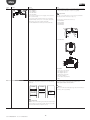
EP SE and EP1 SE sensor with probe
alarm
Analogue input open (no probe 10K@25°C
B=3435).
The sensor is visible on the supervisor,
but is offline
•
•
•
•
Check the communication parameters:
channel
PANID
extended PANID
The sensor is not bound to the Access
Point
Check the NTC probe electrical connection or use the 10 K
terminal resistor supplied with the sensor to simulate a positive temperature of 25 °C.
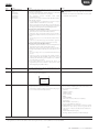
Stimulate the sensor and check the behaviour of LED L3.
Counting the number of flashes indicates whether the sensor
or Router is communicating with various devices.
• There may be multiple devices with the same serial address
Incorrect sensor configuration
•
•
•
•
The repeater is not in the network
• Network not open
• Repeater fault
• Repeater not powered
in the system. Check that there are no other devices with
the same serial ID;
check that the network is open (orange LED flashing fast);
check that the battery protection has been removed;
check the distance between repeater/Access Point;
check the number of devices connected to the Router or
AP. If all the slots are used, add a Router.
• Open the network on the Access Point
• Replace the repeater
• Power up the repeater
Everything is configured correctly, the
Restart the supervisor engineSensor transmissensors are communicating and the
sion time
Access Points are one, but on the supervisor all the devices are offline (grey dot)
• When configuring the site on PVPRO or PWPRO, wait the
When binding a new Router to the wireless network, it is not shown as being
bound (using the rTM SE handheld).
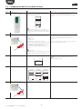
Using the rTM SE handheld, access the new wireless network
and check that the device MAC address has been bound.
Reset the device and repeat the binding sequence, choosing
the right wireless network.
Check that the Router hasn’t created a new
wireless network.
query cycle time before the devices can be seen as online
Tab. 14.a
For further information on the rTM SE system, see the user manual.
rtM +0400030EN - rel. 1.2 - 04.04.2013
44