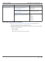
1
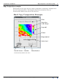
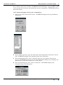
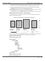
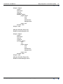
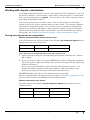
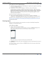
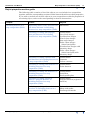
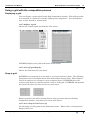
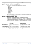
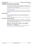
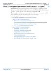
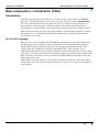
INTREPID User Manual
Library | Help | Top
Map composition—introduction (T45a)
1
| Back |
Map composition—introduction (T45a)
Top
Introduction
The Map Composition tool enables you to create maps representing INTREPID
datasets. The specification as you create it on the screen is called a composition.
You can automatically divide the data into sheets, overlay several datasets (e.g.,
pseudocolour with sun angle, contours, regions and points of interest) on the
composition and include title, text, North arrow, legend, scale bar and sheet index.
Map output from this tool can range from simply composed draft material, perhaps
for internal use, to finished professional standard maps ready for publication or
presentation to a client.
MAPCOMP language
When you save your composition, INTREPID automatically generates instructions
for producing the composition. These instructions use the MAPCOMP language.
MAPCOMP to some extent governs the way that Map Composition works. We
suggest that you familiarise yourself with MAPCOMP. This will help you to
understand the operation of the Map Composition tool and enable you to use it more
efficiently. You will also then have the ability to directly edit and 'clone' MAPCOMP
files. On some occasions you may prefer direct MAPCOMP file editing to using the
Map Composition tool.
MAPCOMP currently allows a wider range of operations than the interactive Map
Composition tool. We will extend the interactive tool to cover all of these operations
in the future.
Library | Help | Top
© 2012 Intrepid Geophysics
| Back |
INTREPID User Manual
Library | Help | Top
Map composition—introduction (T45a)
2
| Back |
Map Composition example
The diagram on this page shows a simple composition containing a multiple sheet
data box and annotations. The diagram shows the annotations that are
automatically linked to the data in the data box.
Hard Copy Composition Example
Title
Data box
with image
Legend*
Ticks*
Edge labels*
Scale bar*
North Arrow*
Border
Sheet Index*
* Automatically linked to the data
Library | Help | Top
© 2012 Intrepid Geophysics
| Back |
INTREPID User Manual
Library | Help | Top
Map composition—introduction (T45a)
3
| Back |
Using Map Composition
>> To use Map Composition with the INTREPID graphic user interface
1
Choose Compose_Hardcopy from the Printing menu in the Project Manager, or
use the command mapcomp.exe. INTREPID displays the Map Composition Main
window.
If you have previously prepared specifications that you wish to modify, load the
corresponding MAPCOMP file using Load Map from the File menu16. If all of the
specifications are correct in this file, go to step 4. If you wish to modify any
settings, carry out the following steps as required.
If you wish to create a new composition, choose New Map from the File menu and
select a template from the Select Map dialog box. If you do not require a template,
select blank.map
(See "Specifying input and output files" in Introduction to INTREPID (R02) for
detailed instructions on loading files and Managing Map Composition templates
for information about templates.)
2
Specify the paper size to be used, datasets to be included, their format, geographic
extent to be used in the composition, margins, borders, division into sheets and
annotations. Use Insert Map from the File menu to insert any composition
components that you have already prepared.
3
If you wish to record the specifications for this composition in a MAPCOMP file in
order to edit the composition later, reprint a similar composition or for some other
reason, use SaveAs Map from the File menu. (See "Specifying input and output
files" in Introduction to INTREPID (R02) for detailed instructions.)
1.6 You can automatically load a MAPCOMP file using the mapcomp.exe command. Add
the file name and path if necessary after the command. Example:
mapcomp.exe /disk1/surv/morg1.map
Library | Help | Top
© 2012 Intrepid Geophysics
| Back |
INTREPID User Manual
Library | Help | Top
4
Map composition—introduction (T45a)
4
| Back |
If you wish to print the composition, choose Print from the File menu.
The Windows version of INTREPID will launch the Print Map tool.
If you are using the Unix version, Map Composition will output your composition
to a printer file in a format or output language you specify (such as TIFF,
PostScript or HP–GL/2). Select the output format from the Print cascade menu.
You can send the output file to your printer using a Unix command.
See Map printing (T46)for full instructions.
5
To exit from Map Composition, choose Quit from the File menu.
Specifying input and output MAPCOMP files
You can
•
Start a new blank composition.
•
Start a new composition based on a Map Composition template.
•
Load an existing MAPCOMP file for editing or 'cloning'.
•
Save the current specifications as a MAPCOMP file.
•
Insert an existing MAPCOMP file into the current composition.
In each case INTREPID displays an Open or Save As dialog box. Use the directory
and file selector to locate the file you require. (See "Specifying input and output files"
in Introduction to INTREPID (R02) for information about specifying files.)
>> To create, load and save compositions
Choose the corresponding option from the File menu.
Load Map Use this to abandon any current composition in the Map Composition
window and load an existing MAPCOMP file.
New Map Use this to abandon any current composition in the Map Composition
window and start a new MAPCOMP file. INTREPID displays the Select Map
dialog box containing a set of Map Composition templates.
Library | Help | Top
© 2012 Intrepid Geophysics
| Back |
INTREPID User Manual
Library | Help | Top
Map composition—introduction (T45a)
5
| Back |
If you wish to use a template, select the template you require and choose Select
Template. INTREPID will load the template and display any visible parts of it.
If you do not wish to use a template, select the blank template, then choose Select
Template. INTREPID displays a blank Map Composition window.
Insert Map If you have a component for the composition stored in a separate
MAPCOMP file, use this option to insert it into your composition. If you do not
have an open group INTREPID will place the objects from the inserted file into
the composition.
SaveAs Map Use this option to save specifications for the current composition as a
MAPCOMP file.
Managing Map Composition templates
A Map Composition template is a MAPCOMP file stored in the install_path/
config directory17. We provide a selection of templates. You can edit or delete these
if required, and also create, edit and delete your own templates. The template
blank.map is an 'empty' template for you to use when you do not require a template.
>> To create a Map Composition template
Create or edit a MAPCOMP file for use as the template, then copy or save the file to
the install_path/config directory.
>> To edit a Map Composition template
Edit the MAPCOMP file in the install_path/config directory using a text editor
or interactively with the Map Composition tool.
>> To delete a Map Composition template
Delete or move the MAPCOMP file from the install_path/config directory.
Page definition
You can formally specify the page for your composition including optional size,
internal margin and border. You can print your composition on A0, A1, A2, A4 paper,
or specify your own page size. The default page size is A4 (210 mm x 297 mm).
Page definition is not essential for a composition. You may choose not to include a
page definition because you may intend your current composition to be a component
for inserting into some other composition.
If you do include a page definition, Map Composition will define it as a group
containing all of the objects in your composition except the optional page margin and/
or page border.
Using the Map Composition tool you cannot select the page definition as an object for
editing. For this reason it has special editing options in the File menu.
You can define a margin and/or border for a page. The margin can be inside or
outside the page dimensions. The border can be inside or outside the margin.
1.7 where install_path is the location of your INTREPID installation. See
INTREPID database, file and data structures (R05) for details.
Library | Help | Top
© 2012 Intrepid Geophysics
| Back |
INTREPID User Manual
Library | Help | Top
Map composition—introduction (T45a)
6
| Back |
If you define a page but no border, INTREPID will still display a page border on the
screen so that you can locate the boundaries of your composition. INTREPID will not
print this border.
>> To choose the page size for your composition,
Library | Help | Top
1
Choose Page Size from the File menu. INTREPID displays the Page Definition
dialog box.
2
If you wish to specify a page size other than A4 with portrait orientation, choose
Size. INTREPID displays the Standard Page Sizes dialog box.
3
For standard page sizes, select (click) the page size you require, then choose
Accept. INTREPID will return to the Page Definition dialog box and display the
dimensions of your chosen page size. Go to step 6.
4
For non-standard page sizes, choose Customize. INTREPID displays the
Customize Page Size dialog box.
© 2012 Intrepid Geophysics
| Back |
INTREPID User Manual
Library | Help | Top
Map composition—introduction (T45a)
7
| Back |
5
Enter the required measurements in the Width and Height text boxes. For
landscape orientation you must enter the width as the larger dimension. Choose
Accept in the Customise Page Size and Standard Page Sizes dialog boxes.
INTREPID will return to the Page Definition dialog box and display the
dimensions you have chosen.
6
Specify page margins as required. See Margins and borders for pages for detailed
instructions about specifying margins.
7
Specify page borders as required. See Margins and borders for pages for detailed
instructions about specifying borders.
8
Choose OK in the Page Definition dialog box. INTREPID will note your
specifications and display visible components in the Map Composition window.
Margins and borders for pages
You can specify the margin and border for a page using the Page Definition dialog
box.
The instructions in this section use this dialog box as their start point.
Margins
You can specify page margins using the defaults provided or directly in mm. Page
margins can be
•
Outside the page dimensions (if you are actually using larger paper than that
defined as the page size), OR
•
Inside the page dimensions (thus reducing the size of the page).
Default page margins are inside the page dimensions.
The original default margins depend on the page size. See Map composition—
introduction (T45a)for a table of standard page sizes and their original default
margins. If you edit the margin sizes INTREPID will apply the interactive default
margins (2 mm) to all margins that you do not specify in the margin editing process,
and the original default margin values will be lost.
Library | Help | Top
© 2012 Intrepid Geophysics
| Back |
INTREPID User Manual
Library | Help | Top
Map composition—introduction (T45a)
8
| Back |
>> To specify page margins
1
If you wish to create a margin for your page, turn on the Margin check box.
2
If you do not wish to change the margin specification, then you have completed
the margin setting process.
If you wish to change the margin specification, choose Edit adjacent to the Margin
check box. INTREPID displays the Page Margin dialog box.
3
The first time you edit the page margins INTREPID changes the default size of
each margin to 2 mm. If you leave all settings in this dialog box unchanged, then
choose Apply, INTREPID will change the page margins to 2 mm.
Specify the size of the margin you require on each edge of the page in the
corresponding text box.
4
Turn the Outside Page Dimensions check box on or off as required, then choose
Apply. INTREPID will return to the Page Definition dialog box.
Outside Page Dimensions If this check box is off, INTREPID will place the margin
inside the page and reduce the page dimensions by the size of the margin. This is
the default setting in the dialog box.
If the check box is on, INTREPID will place the margin outside the page and
retain the existing page dimensions. If you turn on the check box, you must be
intending to print to paper larger than the page size defined.
Borders
You can specify a border as part of your page definition. If you also specify a margin,
the border can be inside or outside the margin.
The default page border is a solid line 1 mm thick outside the page margins.
>> To specify page borders
1
If you wish to create a page border, turn on the Border check box.
2
If you do not wish to change the border specification, then you have completed the
border setting process.
If you wish to change the border specification, choose Edit adjacent to the Border
check box. INTREPID displays the Page Border dialog box.
Library | Help | Top
© 2012 Intrepid Geophysics
| Back |
INTREPID User Manual
Library | Help | Top
Map composition—introduction (T45a)
9
| Back |
3
Specify the attribute values for the border as required. See Specifying map
attribute values (T45e) for instructions about specifying attribute values.
4
Turn the Inside Margin check box on or off as required, then choose Apply.
INTREPID will return to the Page Definition dialog box.
Inside Margin If this check box is off, INTREPID will place the border outside the
page margin. This is the default setting in the dialog box.
If the check box is on, INTREPID will place the border inside the page margin.
Page margins and border options—results summary
The following diagram summarises the effects of the Inside/Outside margin and
border settings for an A4 page.
Inside / Outside Options for Page Borders and Margins
A4
Margin Outside
Page OFF,
Border Inside
Margin OFF
Margin Outside
Page OFF,
Border Inside
Margin ON
Margin Outside
Page ON,
Border Inside
Margin ON
Margin
Border
Margin Outside
Page ON,
Border Inside
Margin OFF
Page Dimension
Here are some examples of MAPCOMP file sections resulting from Inside/Outside
margin and border option combinations with an A4 page definition:
Margin Outside Page OFF,
Border Inside Margin OFF
border begin
margin begin
top=2
bottom=2
left=2
right=2
page begin
X=2
Y=2
Width=206
Height=293
...
page end
margin end
border end
Margin Outside Page OFF,
Border Inside Margin ON
Library | Help | Top
© 2012 Intrepid Geophysics
| Back |
INTREPID User Manual
Library | Help | Top
Map composition—introduction (T45a)
10
| Back |
margin begin
top=2
bottom=2
left=2
right=2
border begin
page begin
X=2
Y=2
Width=206
Height=293
...
page end
border end
margin end
Margin Outside Page ON,
Border Inside Margin ON
margin begin
top=2
bottom=2
left=2
right=2
border begin
X=2
Y=2
page begin
X=0
Y=0
Width=210
Height=297
...
page end
border end
margin end
Margin Outside Page ON,
Border Inside Margin OFF
Library | Help | Top
© 2012 Intrepid Geophysics
| Back |
INTREPID User Manual
Library | Help | Top
Map composition—introduction (T45a)
11
| Back |
border begin
margin begin
top=2
bottom=2
left=2
right=2
page begin
X=2
Y=2
Width=210
Height=297
...
page end
margin end
border end
Zooming your composition view in and out
You can view your composition at seven different magnifications. If you are using
larger than A4 paper or a screen resolution less than 1280x1024, you will need to
zoom out to view the whole composition.
INTREPID provides seven preset zoom levels from 16:1 (maximum zoom out,
displaying the composition 1/16 actual size) to 1:4 (maximum zoom in, displaying the
composition 4 times actual size).
>> To zoom in or out
Choose the Scale option you require from the View menu.
>> To view the upper right section of the composition
Increase the size of the Map Composition window or zoom out (choose a larger scale).
Library | Help | Top
© 2012 Intrepid Geophysics
| Back |
INTREPID User Manual
Library | Help | Top
Map composition—introduction (T45a)
12
| Back |
Working with objects—introduction
In the Map Composition tool we refer to each component of the composition, such as a
dataset in a data box, a North arrow, a sheet index, some text such as a composition
title, or your company logo, as objects. You can create, edit, delete and move objects
in the Map Composition window.
You can also group objects in various ways. You can group objects so that they
remain in the same relative positions when you move them. You can place margins
and borders around these groups. You can also create a group that automatically
organises the position of the objects. After you have created a group you will deal
with it rather than with the objects individually. For full instructions on working
with groups, See Working with objects in maps—advanced operations (T45d).
Placing new objects into the composition
Objects composed before placing on the screen
You will determine the size and shape of the following pre-composed objects before
placing them into your composition.
Data boxes
Scale bars
North arrows
Sheet indexes
Legend
Grey bar
>> To place a pre-composed object into the composition
1
Specify the object using the corresponding menu option and dialog box. Choose
OK or Apply.
2
If you are using the Unix version of INTREPID, an outline will appear attached to
the mouse pointer. Move the outline to the position you require for the object, and
click the left button.
If you are using the Windows version, hold down the left mouse button. An
outline will appear attached to the mouse pointer. Move the outline to the
position you require for the object, and release the left button.
INTREPID displays the object in the position you have specified.
The pre-composed objects belong to various categories. See Object properties section
guide for a list of their corresponding sections in this manual.
Objects composed on the screen
You will compose the following screen-composed objects directly on the screen
using the mouse.
Markers
Lines
Arrows
Polygons
Rectangles
Images
Text
Library | Help | Top
© 2012 Intrepid Geophysics
| Back |
INTREPID User Manual
Library | Help | Top
Map composition—introduction (T45a)
13
| Back |
>> To place a screen-composed object
1
Specify the object using the corresponding menu option and respond to any dialog
box that INTREPID displays.
2
For Markers, Lines, Arrows, Polygons: Click the vertices of the object.
For Rectangles and Images: 'Rubber band stretch' the object. (Move the mouse
pointer to the position for one of the corners of the rectangle or image. Hold down
the left button and drag diagonally across the space for the rectangle or image.
When the mouse pointer is at the position for the diagonally opposite corner,
release the mouse button.)
For Text: Click the starting position, then type the text.
3
Except for Rectangles and Images, press ENTER or RETURN to finish the
composition. INTREPID displays the object in the position you have specified.
All of the screen-composed objects are non-dataset-related annotations. See "Nondataset-related annotations" in Including and editing map annotations (T45c) for
detailed instructions.
Selecting objects
When you wish to perform some operation on an object in the Map Composition
windows, you must first select it.
>> To select an object
1
Click it with the left mouse button.
If there are several objects over the point you choose, INTREPID displays the
Select Object dialog box with a list of the objects under the point.
Select the object you require from the list and choose OK.
2
INTREPID will select the object and display its name in the bottom left corner of
the screen.
If you have chosen a group of objects, INTREPID will select the group rather than
any individual object.
Library | Help | Top
© 2012 Intrepid Geophysics
| Back |
INTREPID User Manual
Library | Help | Top
Map composition—introduction (T45a)
14
| Back |
>> To select a number of objects one by one
Click the first with the left mouse button (and select the item you require from the
Select Object dialog box if it appears). SHIFT+CLICK (hold down SHIFT and left button
click) the other objects that you wish to select (responding to the Select Object dialog
box as required in each case).
If you are selecting objects for inclusion in an HBox or VBox, then the order in which
you select them will determine the order of objects in the box. (See The HBox and
VBox groups in "The HBox and VBox groups" in Working with objects in maps—
advanced operations (T45d).) Otherwise the order in which you select objects does
not matter.
>> To select a number of objects that lie within a region of the Map
Composition window
'Rubber band stretch' a rectangle that encloses the objects. (Move the mouse pointer
to one of the corners of the area. Hold down the left button and drag diagonally
across the area. When the mouse pointer is at the diagonally opposite corner, release
the mouse button.)
Moving objects
>> To move an object in the Map Composition window
Select the object (INTREPID displays the name of the selected object at the bottom of
the window), then:
If you have three buttons enabled on your mouse: Drag the object to the new position
using the centre mouse button.
If you have two buttons only enabled on your mouse: Hold down CTRL and drag the
object to the new position using the left mouse button.
Deleting objects
>> To delete an object
Select it and choose Cut from the Edit menu.
Object display detail
Some objects, such as set of contours and line datasets, are highly complex and often
take a long time to draw on the screen. INTREPID can vary the detail of displayed
objects in order to shorten screen drawing time.
INTREPID can display objects with three levels of detail:
•
Outline—Displays the outline of the object only and outlines of contained objects
•
Draft—Displays limited detail of the object
•
Full—Displays full detail of the object
The default detail setting for Contours, Path plots and Stack Profile plots is Draft.
The default setting for all other objects is Full.
Library | Help | Top
© 2012 Intrepid Geophysics
| Back |
INTREPID User Manual
Library | Help | Top
Map composition—introduction (T45a)
15
| Back |
>> To set detail for an object
1
Select the object.
2
Choose Edit Detail from the Edit menu. INTREPID displays the Edit Detail
dialog box.
3
Choose the detail option you require, then choose OK.
If you set a detail level for a group object, the level applies to all objects within the
group. If you dissolve a group, INTREPID sets the detail of the objects it contained
according to rules explained in Section "Dissolving groups with Detail setting" in
Working with objects in maps—advanced operations (T45d).
Note: Object detail settings only apply to visualising the data on the screen.
INTREPID always prints compositions with full detail.
Editing properties of selected objects
You can edit the properties of any object in your composition. In each case
INTREPID displays the dialog box corresponding to the object.
For screen-composed objects such as lines, arrows, images, sets of markers, etc., this
editing process does not include editing the vertices (changing shape or size) of the
objects. To do this you must manually edit the MAPCOMP file or delete the object
and draw it again. INTREPID can edit the line thickness, colour, style, etc., of
geometric objects.
>> To edit an existing object
1
Double click a point on the object that is not overlapping another object.
OR
Select the object using the method described above (See Selecting objects), then
choose Edit Object from the Edit menu.
If the object overlaps another object and no part of it protrudes by itself you must
use the second of the above methods.
Library | Help | Top
© 2012 Intrepid Geophysics
| Back |
INTREPID User Manual
Library | Help | Top
Map composition—introduction (T45a)
16
| Back |
2
If the object is a data box or group object, INTREPID displays the Select
Contained Object dialog box for you to select the group or one of its contained
objects for editing.
3
INTREPID displays the object properties dialog box corresponding to the object
you have selected. See Object properties section guide for a list of the types of
object and sections that describe their properties.
Edit the properties as required, then choose OK or Apply. INTREPID displays the
object with its new properties.
Library | Help | Top
© 2012 Intrepid Geophysics
| Back |
INTREPID User Manual
Library | Help | Top
Map composition—introduction (T45a)
17
| Back |
Object properties section guide
The following table contains a list of the objects you can include in a composition,
together with the corresponding sections in this manual that discuss their properties.
If you wish to include one of these objects in your composition or edit the properties of
an existing object, refer to the corresponding section for instructions.
Chapter
Section
Objects
Including datasets in a
map composition (T45b)
"Specifying extent, scale, data box size
and sheets division" in Including
datasets in a map composition (T45b)
Data boxes
"Including or editing filled images
from grid datasets" in Including
datasets in a map composition (T45b)
In data boxes:
Grey Scale images
Pseudocolour images
Fixed colour images
Sun angle images
False colour images
(three band grids)
Pseudocolour images with
intensity drape
False colour images
(three band grid) with
intensity drape
"Including or editing contours from
grid datasets" in Including datasets in
a map composition (T45b)
In data boxes:
Contours
Colour contours
"Including or editing point datasets" in
Including datasets in a map
composition (T45b)
In data boxes:
Point datasets
"Including or editing line datasets" in
Including datasets in a map
composition (T45b)
In data boxes:
Path Plots
Stack profile plots
"Including or editing regions of
interest—polygon datasets" in
Including datasets in a map
composition (T45b)
In data boxes:
Polygon datasets (regions of
interest)
"Including or editing tick marks in a
data box" in Including datasets in a
map composition (T45b)
In data boxes:
Metre tick marks
Lat/Long tick marks
Library | Help | Top
© 2012 Intrepid Geophysics
| Back |
INTREPID User Manual
Library | Help | Top
Map composition—introduction (T45a)
18
| Back |
Chapter
Section
Objects
Including and editing map
annotations (T45c)
"Geographically related annotations"
in Including and editing map
annotations (T45c)
Scale bar
North arrow
Sheet index
"Annotations that describe grid and Z
data" in Including and editing map
annotations (T45c)
Legend
Profile graph (XY Plot)
"Non-dataset-related annotations" in
Including and editing map annotations
(T45c)
Markers
Lines
Arrows
Polygons
Text
Grey bars
Images
Object topics covered later in this manual
Working with objects in maps—advanced operations (T45d) describes how to:
Library | Help | Top
•
Arrange the apparent layers for overlapping objects.
•
Create groups of objects that then behave as a single object. As well as containing
the objects, these groups can
•
Have a margin,
•
Have a border,
•
Align their contained objects in various ways.
© 2012 Intrepid Geophysics
| Back |
INTREPID User Manual
Library | Help | Top
Map composition—introduction (T45a)
19
| Back |
Using a grid with the composition process
Displaying a grid
You can display a grid overlaid on the Map Composition window. This will not print–
it is intended as a guide for correctly aligning your components. You can display 5
mm, 10 mm, 20 mm or 40 mm grids.
>> To display a grid
Choose the required grid size from the View menu.
INTREPID displays the grid in the form of tick marks.
>> To turn off grid display
Choose No Grid from the View menu.
Snap to grid
INTREPID can snap objects to the grid as you insert and move them. The following
illustrations show rectangles drawn with and without Snap to Grid. When Snap to
Grid is on and you are creating a screen-composed object, INTREPID forces the
vertices of the object to coincide with the vertices of the grid. INTREPID will position
the lower left corner of a line of text on a grid vertex.
Snap to grid does not affect existing objects when you move them in the Map
Composition window– only when you create new objects.
>> To turn Snap to Grid on or off
Use the Snap to Grid option in the Annotation menu. When it has a tick against it,
Snap to Grid is on.
Library | Help | Top
© 2012 Intrepid Geophysics
| Back |
INTREPID User Manual
Library | Help | Top
Map composition—introduction (T45a)
20
| Back |
Frequently Asked Questions
Q : Is it possible to have a dashed line style in path plot? There are Style
options for Dash and DashDot in the GUI, but these don't appear to plot any
differently to Style = Solid
A : The support for dashed line style depends on the driver being used. The TIF driver
does not support a dashed line style, whereas most of the HP plotter drivers do. As of
2007, the only drivers attempting to do anything with the line style are the Postscript
and the Mapinfo drivers. The WIn32 driver is currently being looked at.
Library | Help | Top
© 2012 Intrepid Geophysics
| Back |