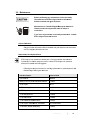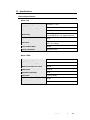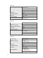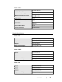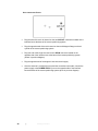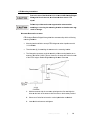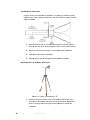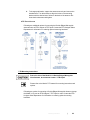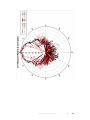
1
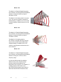
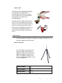
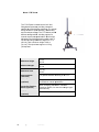
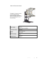
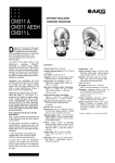
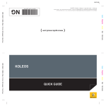
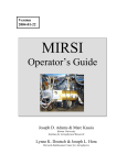
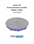
Models 3112, 3106B, 3119, 3115, 3117, 3116C Double-Ridged Waveguide Horn Antennas User Manual ETS-Lindgren L.P. reserves the right to make changes to any products herein to improve functioning or design. Although the information in this document has been carefully reviewed and is believed to be reliable, ETS-Lindgren does not assume any liability arising out of the application or use of any product or circuit described herein; nor does it convey any license under its patent rights nor the rights of others. All trademarks are the property of their respective owners. © Copyright 2010–2012 by ETS-Lindgren L.P. All Rights Reserved. No part of this document may be copied by any means without written permission from ETS-Lindgren L.P. Trademarks used in this document: The ETS-Lindgren logo is a trademark of ETS-Lindgren L.P. Revision Record | Double Ridged Waveguide Horn Antenna, MANUAL Part #399318, Rev. B Revision Description Date A Initial Release October, 2010 B Update 3116B to 3116C. Updates to all sections: ii | May , 2012 Table of Contents Notes, Cautions, and Warnings ........................................................................ iv 1.0 Introduction ................................................................................................... 5 Optional Items..................................................................................................................... 7 ETS-Lindgren Product Information Bulletin ...................................................................... 10 2.0 Maintenance ................................................................................................ 11 Annual Calibration ............................................................................................................ 11 Replacement and Optional Parts...................................................................................... 11 Service Procedures .......................................................................................................... 12 3.0 Specifications.............................................................................................. 13 Electrical Specifications .................................................................................................... 13 Physical Specifications ..................................................................................................... 15 4.0 Mounting Instructions ................................................................................ 17 Model 3112 Optional Positioning System......................................................................... 17 4-TR Mounting Instructions .............................................................................................. 21 7-TR Mounting Instructions .............................................................................................. 23 5.0 Typical Data ................................................................................................. 27 Model 3112 ....................................................................................................................... 27 Model 3106B..................................................................................................................... 29 Model 3119 ....................................................................................................................... 31 Model 3115 ....................................................................................................................... 34 Model 3117 ....................................................................................................................... 37 Model 3116C .................................................................................................................... 40 Appendix A: Warranty ...................................................................................... 43 Appendix B: Typical Measured Radiated Patterns ........................................ 45 | iii Notes, Cautions, and Warnings Note: Denotes helpful information intended to provide tips for better use of the product. Caution: Denotes a hazard. Failure to follow instructions could result in minor personal injury and/or property damage. Included text gives proper procedures. Warning: Denotes a hazard. Failure to follow instructions could result in SEVERE personal injury and/or property damage. Included text gives proper procedures. See the ETS-Lindgren Product Information Bulletin for safety, regulatory, and other product marking information. iv | 1.0 Introduction The ETS-Lindgren family of Double-Ridged Waveguide Horn Antennas consists of linearly polarized broadband antennas ranging in frequency from 100 MHz to 40 GHz. These antennas were designed and built specifically from EMI measurements and specifications compliance testing. However, they can also be used for antenna gain, pattern measurement, surveillance, automotive and military EMC immunity applications. MODEL 3112 The Model 3112 Double-Ridged Waveguide Horn Antenna is a linearly polarized antenna covering the frequency range of 100 MHz to 1 GHz. The Model 3112 is especially effective for generating high electromagnetic fields with relatively low power input. The antenna is also useful for receiving low-level signals where high gain characteristics are needed. MODEL 3106B The Model 3106B Double-Ridged Waveguide Horn Antenna is a linearly polarized broadband antenna covering a frequency range of 200 MHz to 2.5 GHz. It is precision machined from aluminum, making it lightweight and durable. Two brackets are attached to the sides of the antenna so it can be polarized either horizontal or vertically. The Model 3106B has high gain and excellent VSWR characteristics over the entire frequency range (see Appendix B). It is especially effective for generating high electromagnetic field with relatively low power input. The antenna is also useful for receiving low level signals where high gain characteristics are needed Introduction | 5 MODEL 3119 The Model 3119 Double-Ridged Waveguide Horn Antenna is a linearly polarized broadband antenna covering the frequency range of 400 MHz to 6 GHz. The Model 3119 is ideally suited for immunity over 1 GHz and as a reference antenna for wireless testing. In addition, the 3119 is useful for antenna pattern measurement as a source antenna. MODEL 3115 The Model 3115 Double-Ridged Waveguide Horn Antenna is a linearly polarized broadband antenna covering the frequency range of 750 MHz to 18 GHz The Model 3115 is ideally suited for IEC 61000-4-3 and MIL-STD 461E immunity tests as well as ANSI C634 and EN 55033 emissions testing. In addition, the 3115 is useful for antenna pattern measurement as a source antenna MODEL 3117 The Model 3117 Double-Ridged Waveguide Horn Antenna is a linearly polarized broadband antenna covering the 1 GHZ to 18 GHz frequency range. A single well defined main lobe radiation pattern over the entire frequency range provides excellent illumination of the Equipment Under Test (EUT). The Model 3117 is ideally suited for IEC 6100-4-3 and MIL-STD 661/462 immunity tests as well as ANSI C634 and EN 55033 emissions tests. 6 | Introduction MODELL 3116C The Model 3116C 3 Double e-Ridged Wav veguide Horn Antenn na is a linearly y polarized broadband antenna a covering the frequ uency range 10 GH Hz to 40 GHz. It is designe ed and built specific cally for emiss sions and susceptibility y testing. The Model 3116C 3 is prec cision machined from aluminum. A 50 Ω Type K (2.92 mm) female f connector is s mounted on the base bloc ck of the antenna for increased performance at high frequencies.. For flexible mounting m optiions, the 3116C includes a brackett that accepts s a ¼” 20 thread sc crew and also o a rear stinge er style mount. Optional Items ET TS-Lindgren offers o the follo owing non-me etallic, non-re eflective tripod ds for use at bo oth indoor and d outdoor EMC test sites. MODELL 4-TR TRIPOD D Th he 4-TR Tripo od is construc cted of linen ph henolic and de elrin, designe ed with an ad djustable centter post for prrecise height ad djustments. Maximum M heig ght is 2.0m (80.0 in), and minimum m heig ght is 94 cm t can sup pport up to an n (37.0 in). This tripod 1.8 kg (26.0 lb bs) load 11 Maximum He eight Minimum He eight Maximum Lo oad 2m 80 in 94 cm 37 in 11.8 kg 26 lbs Introducction | 7 MODELL 7-TR TRIPOD D The 7-TR R Tripod is con nstructed of PVC P and fiberglass s components s, providing in ncreased stability fo or physically large l antenna as. The uniqu ue design allows for quick k assembly, disassembly d venient storag ge. The 7-TR allows severa al and conv different configurations c s, including options for manual or o pneumatic polarization. p Quick Q height adjustment and locking g wheels prov vide ease of use durin ng testing. Ma aximum height is 2.17 m (85.8 in), with a minimum height of 0.8 m an support a 13.5 kg (31.8 in). This tripod ca oad. (30 lbs) lo Maximum m Height 2.17m 85.8 in Minimum m Height 0.8m 31.8 in Maximum m Load 13.5 kg 30 lbs Straight Boom (standard) For generral antenna m mounting on a 7-TR Offset Bo oom (optional) For generral antenna m mounting on a 7-TR with pneumatic c or manual p polarization Centerlin ne Rotation Boom (o optional) When cha anging polarizzation, mainta ains centerline e rotation, for rear-mount sstinger-type antennas only 7-TR Boo om (optional) 8 | For Mode el 3106B ante nna only Introduction MODEL 3112 POSITIONING SYSTEM The Model 3112 features an option for a fixed height pneumatic assisted polarization positioning system. The position system is ideal when using the Model 31112 for immunity testing. Power Supply 160 mA 120 VAC Optional 220 VAC available Pneumatic Interface 50-80 PSI Weight 181.43 - 226.76 kg 400 -500 lbs Maximum Height 355.6 cm 140 in Maximum Load 194.13 cm 76.43 in Introduction | 9 ETS-Lindgren Product Information Bulletin See the ETS-Lindgren Product Information Bulletin included with your shipment for the following: 10 | Warranty information Safety, regulatory, and other product marking information Steps to receive your shipment Steps to return a component for service ETS Lindgren calibration service ETS Lindgren contact information Introduction 2.0 Mainte enance Before perfforming any maintenance, follow the e safety information n in the ETS--Lindgren Prroduct Inform mation Bulletin inc cluded with y your shipment. WAR RRANTY Maintenanc ce of a Doub ble-Ridged W Waveguide An ntenna is limited to external e com ponents suc ch as cables or connectors s. If you have e any questio ons concerniing maintena ance, contac ct ETS Lindgrren Custome er Service. Annual Ca alibration Se ee the Produc ct Information n Bulletin inclu uded with you ur shipment fo or information n on n ETS-Lindgre en calibration services. Replacem ment and Optional Parts ETS-L Lindgren may substitute a similar s part o r new part nu umber with the e same functio onality for ano other part/parrt number. Co ontact ETS-Lin ndgren for qu uestions about part numbers s and ordering g parts. Fo ollowing are th he part numbers for orderin ng replaceme ent or optiona al parts for the e Do ouble-Ridged Waveguide Antennas. A Part Des scription P Part Numberr User Ma anual 3 399318 Model 3112 Pneumattic Assisted Pedestal P 109621 4-TR Tripod 4 4-TR 4-TR Mo ounting Brack ket 101501 7-TR Tripod 7 7-TR 7-TR Strraight Boom 109042 7-TR Offfset Boom 108983 7-TR Ce enterline Rota ation Boom 108197 7-TR Tripod, 3106B Mount, M Pneum matic 7 7-TR/POL-31 106 7-TR Bo oom, Model 31 106B Only 108507 Maintena nce | 11 Service Procedures For the steps to return a system or system component to ETS-Lindgren for service, see the Product Information Bulletin included with your shipment. 12 | Maintenance 3.0 Specifications Electrical Specifications MODEL 3112 Frequency Range 100 MHz—1 GHz VSWR Ratio (Average) < 1.6:1 Maximum Continuous Power 800 W Peak Power 1.5 kW (Type N, female connector) 2.5 kW CW (EIA 1 ⅝ in. flange connector) Impedance (Nominal) 50 Ω Connector Type N, female EIA 1 ⅝ in. flange Front-to-Back Ratio 20 dB Cross Polarization 20 dB minimum MODEL 3106B Frequency Range 200 MHz—2.5 GHz VSWR Ratio (Average) <1.6:1 Maximum Continuous Power 800 W Peak Power 1600 W Impedance (Nominal) 50 Ω Connector Type N, female Front-to-Back Ratio 20 dB Cross Polarization 20 dB minimum Specifications | 13 MODEL 3119 Frequency Range 400 MHz—6 GHz VSWR Ratio (Average) 3.5:1 Maximum Continuous Power 800 W Peak Power 2500 W Impedance (Nominal) 50 Ω Connector Type N, female Front-to-Back Ratio 20 dB Cross Polarization 20 dB minimum MODEL 3115 Frequency Range 750 MHz—18 GHz VSWR Ratio (Average) 5:1 Maximum Continuous Power 750 W Peak Power 500 W Impedance (Nominal) 50 Ω Connector Type N, female Front-to-Back Ratio 20 dB Cross Polarization 20 dB minimum MODEL 3117 14 Frequency Range 1 GHz—18 GHz VSWR Ratio (Average) 3.5:1 max <2:1 above 1.5 GHz Maximum Continuous Power 300 W Peak Power 400 W Impedance (Nominal) 50 Ω Connector Type N, female Front-to-Back Ratio >6.42 dB at 1 GHz >12.08 dB at 2 GHz >20 dB at 3 GHz—18 GHz Cross Polarization 20 dB at 3 GHz—18 GHz | Specifications MODEL 3116C Frequency Range 10 GHz—40 GHz VSWR Ratio (Average) 2.5:1 max Maximum Continuous Power 20 W @ 40 GHz 40 W @ 10 GHz Peak Power 200 W Impedance (Nominal) 50 Ω Connector Type K, female 2.92 mm Front-to-Back Ratio 20 dB Cross Polarization 20 dB minimum Physical Specifications MODEL 3112 Width 203.2 cm (80 in) Depth 182 cm (71.65 in) Height 139.7 cm (56 in) Approximate Weight 86.1 kg (189.81 lbs) MODEL 3106B Width 93.3 cm (36.7 in) Depth 97.8 cm (38.5 in) Height 72.9 cm (28.7 in) Approximate Weight 11.8 kg (26.01 lbs) MODEL 3119 Width 48.84 cm (19.23 in) Depth 40 cm (15.74 in) Height 31.37 cm (12.35 in) Approximate Weight 7.4 kg (16.3 lbs) Specifications | 15 MODEL 3115 Width 24.4 cm (9.6 in) Depth 27.9 cm (11 in) Height 15.9 cm (6.2 in) Approximate Weight 1.8 kg (4 lbs) MODEL 3117 Width 17.5 cm (6.9 in) Depth 17.5 cm + 15.5 cm mount (6.9 in + 6.1 in mount) Height 15.5 cm (6.1 in) Approximate Weight 1.13 kg (2.5 lb) MODEL 3116C 16 Width 10.8 cm (4.25 in) Depth with stinger: 25.73 cm (10.13 in) with bracket 13.03 cm (5.13 in) Height With stinger: 6.35 cm (2.5 in) with bracket: 8.9 cm (3.5 in) Approximate Weight With stinger 0.334 kg (0.74 lbs) with bracket: 0.201 kg ( 0.44 lbs) | Specifications 4.0 Mounting Instructions Before connecting any components, follow the safety information in the ETS-Lindgren Product Information Bulletin included with your shipment. The ETS-Lindgren Double-Ridged Waveguide Horn Antennas are precision instruments. Handle with care. Make sure that no part of the antenna is in contact with the tripod or tower. Model 3112 Optional Positioning System Failure to provide continuous support of the antenna when attaching or removing the antenna from the positioning system may result in damage and/or personal injury. The customer is responsible for providing an adequate and safe support system for the Model 3112 Double Ridged Waveguide Horn Antenna when moving and attaching to the optional positioning system. Mounting Instructions | 17 The Model 3112 Double Ridged Waveguide Horn antenna includes a series of outer holes in the rear plate that is compatible with the optional positioning system. Additionally, the mounting holes can be used to meet customer specific mounting requirements. 18 | Mounting Instructions CONNECTING THE OPTIONAL POSITIONING SYSTEM Once the Model 3112 is securely mounted on the positioner, loosen the nuts and turn the wheel at the base of the horn support for better field uniformity. This bore sights the horn 10 degrees. MODEL 3112 INPUT LOCATIONS Do not connect power to the positioner until the antenna is securely mounted and all other connections have been made. The input panel is located on the base of the Model 3112 positioner. Plug one end of the fiber optic cable into the FIBER OPTIC INPUT connector. Plug the opposite end of the fiber optic cable into the ETS-Lindgren Model 2090 Multi-Device Controller or compatible controller. Plug the cord included first into the POWER SUPPLY outlet. Make connection with the power source only once all other connections have been made and the antenna is securely attached to the positioner. Mounting Instructions | 19 AIR POLARIZATION OPTION 20 Plug the ends of the twin air hoses into the two AIR OUT connectors located on the interface box at the base of the custom positioning system. Plug the opposite ends of the twin hoses into the two 90 degree fittings on the air cylinder of the custom positioning system. Plug one end of the single air hose into the AIR IN connector located on the opposite side of the interface box at the base of the custom positioning system (shown in previous diagram). Plug the opposite end of the single air hose into the air supply. Once the antenna is completely secure and the connections are made, connect the power supply to the POWER SUPPLY port on the opposite side of the interface box at the base of the custom positioning system (show in previous diagram). | Mounting Instructions 4-TR Mounting Instruc ctions Due to the size of o the Model 3 3112, 3119 a and 3106B Do ouble-Ridged d Wave eguide Horn Antennas, d do not moun nt them onto a 4-TR tripo od. Failu ure to provide e continuous s support off the antenna a when y attac ching or removing the mo ounting brac cket or thumbscrews may result in damage e. MOUNTTING BRACKETT ATTACHMENT ET TS-Lindgren Double-Ridge D ed Waveguide e Horn antenn nas ship with the following mo ounting hardw ware: Mounting bracket b drilled to accept ET TS-Lindgren o or other tripod d mount with ¼─20 threa ads. Thumbscre ews (2) for atta aching the an ntenna to the mounting bra acket. The illustration represen nts a typical asssembly of th he mounting b bracket to an antenna. Th he Model 311 16C is shown ; however, the steps are similar for eacch of the ETS--Lindgren Dou uble-Ridged W Waveguide H Horn Antennass. 1. Hold th he antenna with the connecctor pointing tto the floor an nd align the holes on o the back off the antenna with the oness on the braccket provided. 2. Select set of holes fo or horizontal or vertical po olarization as d desired. b thumbscrews and tigh hten. 3. Insert both Mou unting Instruction ns | 21 STINGE ER MOUNT ATT TACHMENT A stinger mount is included with w the Mode el 3117 anten nna for centerrline rotation me easurements. When using the Model 31 117 with the 4 4-TR the mou unting brackett mu ust be attache ed. 1. Hold th he antenna with the connecctor pointing tto the floor an nd align the holes on o the back off the antenna with the oness on the braccket provided. 2. Select set of holes fo or horizontal or vertical po olarization as d desired. b thumbscrews and tigh hten. 3. Insert both 4. Align th he stinger with h the threade ed mounting sstud then tightten. MOUNTT ANTENNA TO O THE MODEL 4-TR 4 TRIPOD Mo odel 3117 sho own mounted d onto 4-TR 1. Attach the mounting g bracket to th he 4-TR tripod d by aligning tthe ¼-20 connec ctor on the bra acket with the e ¼-20 bolt on n the tripod. S Support the antenna securely wh hile turning th he mounting b bracket to tigh hten the connec ction 22 2 | Mounting Instru uctions 2. To change polarization, support the antenna securely and remove the thumbscrews. Turn the antenna to align the holes on the mounting bracket with the desired set of holes on the back of the antenna. Reinsert the thumbscrews and tighten. 4-TR TRIPOD OPTIONS Following are additional options for mounting the Double-Ridged Waveguide antennas onto an ETS-Lindgren 4-TR Tripod. Contact the ETS-Lindgren Sales Department for information on ordering optional mounting hardware. 7-TR Mounting Instructions Due to the size of the Model 3112 Double-Ridged Waveguide Horn Antenna, do not mount it onto a 7-TR tripod. Please refer to the Model 7-TR manual for mounting instructions and options. Following are options for mounting a Double-Ridged Waveguide Antenna (except the Model 3112) onto an ETS-Lindgren 7-TR Tripod or mast. Contact the ETSLindgren Sales Department for information on ordering optional mounting hardware. Mounting Instructions | 23 7-TR TRIPOD OPTIONS 109042 boom—Straight boom; for general antenna mounting on a 7-TR 108983 boom—offset boom; for general antenna mounting on a 7-TR with pneumatic or manual polarization; can also be used to mount stinger-type antennas 108507 boom—Centerline rotation boom for Model 3106 Series antennas only; when changing polarization, maintains centerline rotation 24 | Mounting Instructions 2X2 BOOM MOUNTING OPTIONS 2x2 boom refers to a typical 2-inch by 2-inch boom. Following are additional options for mounting the Double-Ridged Waveguide Antenna onto a 2x2 boom. Contact the ETS Lindgren Sales Department for information on ordering optional mounting hardware. Mounting Instructions | 25 MOUNT ANTENNA TO 7-TR POSITIONER Please review the mounting instructions included in the Model 7-TR manual. 7-TR shown with Model 3106B mounted onto 7-TR with optional 108507 centerline rotation boom 26 | Mounting Instructions 5.0 Typical Data Before placing into operation, follow the safety information in the ETS-Lindgren Product Information Bulletin included with your shipment. Model 3112 Typical Data | 27 28 | Typical Data Model 3106B Typical Data | 29 30 | Typical Data Model 3119 Typical Data | 31 32 | Typical Data Typical Data | 33 Model 3115 34 | Typical Data Typical Data | 35 36 | Typical Data Model 3117 Typical Data | 37 38 | Typical Data Typical Data | 39 Model 3116C 40 | Typical Data Typical Data | 41 42 | Typical Data Appendix A: Warranty See the Product Information Bulletin included with your shipment for the complete ETS-Lindgren warranty for your double ridged Waveguide horn antenna. DURATION OF WARRANTIES FOR DOUBLE RIDGED WAVEGUIDE HORN ANTENNAS All product warranties, except the warranty of title, and all remedies for warranty failures are limited to two year. Product Warranted Duration of Warranty Period Model 3112 Model 3106B Model 3119 Model 3115 Model 3117 Model 3116C 2 Years 2 Years 2 Years 2 Years 2 Years 2 Years Warranty | 43 This page intentionally left blank. 44 | Warranty Appendix B: Typical Measured Radiated Patterns MODEL 3106B Typical Measured Radiated Patterns | 45 46 | Typical Measured Radiated Patterns Typical Measured Radiated Patterns | 47 48 | Typical Measured Radiated Patterns Typical Measured Radiated Patterns | 49 MODEL 3119 50 | Typical Measured Radiated Patterns Typical Measured Radiated Patterns | 51 52 | Typical Measured Radiated Patterns Typical Measured Radiated Patterns | 53 54 | Typical Measured Radiated Patterns Typical Measured Radiated Patterns | 55 MODEL 3115 56 | Typical Measured Radiated Patterns Typical Measured Radiated Patterns | 57 58 | Typical Measured Radiated Patterns Typical Measured Radiated Patterns | 59 60 | Typical Measured Radiated Patterns Typical Measured Radiated Patterns | 61 MODEL 3117 62 | Typical Measured Radiated Patterns Typical Measured Radiated Patterns | 63 64 | Typical Measured Radiated Patterns Typical Measured Radiated Patterns | 65 66 | Typical Measured Radiated Patterns Typical Measured Radiated Patterns | 67 68 | Typical Measured Radiated Patterns Typical Measured Radiated Patterns | 69 70 | Typical Measured Radiated Patterns Typical Measured Radiated Patterns | 71 72 | Typical Measured Radiated Patterns Typical Measured Radiated Patterns | 73 This page intentionally left blank. 74 | Typical Measured Radiated Patterns