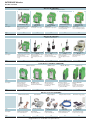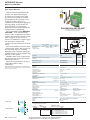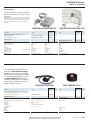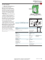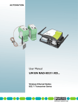
1
604
PHOENIX CONTACT
Courtesy of Power/mation. 1310 Energy Lane, Saint Paul, MN 55108
[email protected] - 800-843-9859 - www.powermation.com
INTERFACE Wireless
Industrial wireless communication
The INTERFACE product range of
wireless signal transmission systems from
Phoenix Contact can be used for easy and
safe wireless transmission of analog and
digital signals or serial data.
This gives planners and users access to a
very simple transmission path for industrial
fields of application. Signals that could
previously only be acquired with a great deal
of effort or not at all are now fast and
simple to acquire.
Depending on the requirements, various
wireless technologies are available:
Trusted Wireless
Trusted Wireless is a specially designed
wireless technology for industrial
applications. The FHSS method is used for
band spread, which guarantees a high
immunity to interference. Trusted Wireless
is characterized by the following features:
– Wide ranges* from a few hundred meters
to several kilometers
– Rugged and reliable communication in an
industrial environment
– License-free industrial, scientific, and
medical band
– Good diagnostics options
– High local system density of several
hundred networks possible
– Can be operated parallel to WLAN 802.11 and Bluetooth systems without
interference
Bluetooth
With Bluetooth, which also operates on
the FHSS principle, it is possible to set up
local wireless networks with up to seven
devices. Thanks to a variety of application
profiles, the standard can be used flexibly
for different tasks. Its features include:
– Range* typ. up to 100 m in industrial halls
and up to 200 m outdoors
– Cyclical and fast transmission of small
data packets
– High local system density, i.e.
interference-free parallel operation of
many Bluetooth networks possible
– Interference-free parallel operation of
WLAN-802.11 networks
– High data integrity due to 128-bit data
encoding and device authentication
Program overview
Product overview
605
RAD-Line (2400 MHz)
RAD-Line IO – bidirectional (BD) wireless system
RAD-Line IO – extension modules
RAD-Line IO – unidirectional (UD) wireless system
RAD-Line Serial IO
RAD-Line Serial
RAD-Line accessories
Systems for autonomous power supply
609
610
612
615
618
619
624
PSI-WL-...Bluetooth (2400 MHz)
626
PSI Modem Line (GPRS/GSM)
630
RAD-Line (900 MHz)
RAD-Line IO – bidirectional (BD) wireless system
RAD-Line IO – extension modules
RAD-Line IO – unidirectional (UD) wireless system
RAD-Line IO – XD wireless system
RAD-Line Serial
RAD-Line Ethernet
RAD-Lineaccessories
Solar systems for autonomous power supply
633
634
636
638
641
642
644
648
GPRS
GPRS (General Packet Radio Service) is
an additional service to exchange data using
the mobile GSM telephone network
(Global System for Mobile
Communications). The TCP/IP based GPRS
connections have the following advantages:
– Invoicing is based on data volumes and
not on the connection time
– Permanent connection, i.e. a timeconsuming dial-in procedure is omitted
– Available worldwide in over 200 countries
– Transmission speeds of up to 85,600 bps
* The range can be considerably exceeded or undershot and depends on
the environment, the antennae technology and the product used.
Courtesy of Power/mation. 1310 Energy Lane, Saint Paul, MN 55108
[email protected] - 800-843-9859 - www.powermation.com
PHOENIX CONTACT
605
INTERFACE Wireless
Product overview
Wireless IO (2400 MHz)
RAD-Line IO bidirectional
Type
RAD-ISM-2400-...-BD...
Description
Page
Bidirectional wireless system,
with Trusted Wireless, can be
extended with IO extension
modules
RAD-Line IO extension modules
RAD-IN-4A-I
RAD-OUT-4A-I
Analog module,
for four inputs or four outputs
609
RAD-IN-8D
RAD-OUT-8D-REL
Digital module,
for eight inputs or eight outputs
610
RAD-IN+OUT-2D-1A-I
Analog/digital module,
for two digital inputs/outputs and
one analog input/output
610
RAD-IN-2D-CNT
RAD-OUT-2D-CNT
Digital module,
for two counter/frequency inputs
or two counter/frequency outputs
611
611
Wireless IO (2400 MHz)
RAD-Line IO unidirectional
Type
RAD-ISM-2400-SET-UD-ANT
Description
Page
Unidirectional wireless system,
with Trusted Wireless,
transmitter and receiver in IP20
housing
RAD-ISM-2400-PIPE-TX-MERX-UD
Unidirectional wireless system,
with Trusted Wireless,
transmitter (IP65) and receiver
(IP20)
RAD-ISM-2400-PIPE-SET-UDANT
Unidirectional wireless system,
with Trusted Wireless,
transmitter and receiver (IP65)
RAD-ISM-2400-ME-TX-PIPERX-UD
Unidirectional wireless system,
with Trusted Wireless,
transmitter (IP20) and receiver
(IP65)
RAD-ISM-2400-SET-UDRPS...EX
Unidirectional wireless system,
with Trusted Wireless,
for Ex zone 1
612
613
613
613
614
RAD-Line Serial
PSI-WL-...Bluetooth
PSI-Modem Line
RAD-ISM-2400-DATA-BD
PSI-WL-...
PSM-Modem...
Serial Wireless (2400 MHz / GPRS/GSM)
RAD-Line Serial IO
Type
RAD-ISM-2400-DATA-BD-BUS
RAD-ISM-TW-PB-GATEWAY
Description
Wireless transceiver,
with Trusted Wireless,
for serial interfaces (RS-232,
RS-422/RS-485), can be extended
with IO extension modules
PROFIBUS coupler,
for wireless transceiver
RAD-ISM-2400-DATA-BD-BUS
Page
Wireless transceiver,
with Trusted Wireless,
for serial interfaces (RS-232,
RS-422/RS-485)
616
617
Omnidirectional antennas
Panel antennas
Adapters/splitters
RAD-ISM-2400-ANT...
RAD-ADP..., CN-LAMBDA...,
RAD-ISM-2400_SPL...
Adapters/splitters,
for the 2.4 GHz ISM band
Bluetooth converter,
to convert from RS-233 (V.24),
RS-422 or RS-485 2-wire to
Bluetooth wireless transmission,
e.g. Modbus, PROFIBUS
618
Industrial GPRS/GSM
modems,
for all GMS networks 850/900/
1800/1900, switching inputs and
outputs, password protection
626
630
Adapters/extensions cables
Autonomous energy supply
Wireless accessories (2400 MHz)
Type
RAD-ISM-2400-ANT...
Description
Page
606
Omnidirectional antennas,
for the 2.4 GHz ISM band
620
PHOENIX CONTACT
Panel antennas,
for the 2.4 GHz ISM band
621
RAD-PIG...
RAD-CAB...
Adapters/extensions cables,
for the 2.4 GHz ISM band
622
Courtesy of Power/mation. 1310 Energy Lane, Saint Paul, MN 55108
[email protected] - 800-843-9859 - www.powermation.com
623
RAD-SOL-SET...
RAD-BAT...
Solar and battery systems,
for autonomous power supply
624
INTERFACE Wireless
Product overview
Wireless IO (900 MHz)
RAD-Line IO bidirectional
RAD-ISM-900-...-BD...
Bidirectional wireless system,
with Trusted Wireless,
can be extended with IO extension
modules
RAD-Line IO extension modules
RAD-IN-4A-I
RAD-OUT-4A-I
Analog module,
for four inputs or four outputs
633
RAD-IN-8D
RAD-OUT-8D-REL
Digital module,
for eight inputs or eight outputs
634
RAD-IN+OUT-2D-1A-I
Analog/digital module,
for two digital inputs/outputs and one
analog input/output
634
RAD-IN-2D-CNT
RAD-OUT-2D-CNT
Digital module,
for two counter/frequency inputs or two
counter/frequency outputs
634
634
Wireless IO (900 MHz)
RAD-Line IO unidirectional
RAD-ISM-900-SET-UD-ANT
Unidirectional wireless system,
with Trusted Wireless,
transmitter and receiver in IP20 housing
636
RAD-Line IO XD
RAD-ISM-900-SET-...UD
RAD-ISM-900-XD-BUS
Unidirectional wireless system,
with Trusted Wireless,
transmitter (IP65) and receiver (IP20)
XD wireless system,
with Trusted Wireless,
can be extended with IO extension
modules
637
638
Serial Wireless (900 MHz)
RAD-Line Serial IO
RAD-ISM-900-DATA-BD-BUS
Wireless transceiver,
with Trusted Wireless, for serial interfaces
(RS-232, RS-422/RS-485),
can be extended with IO extension
modules
Wireless Ethernet (900 MHz / 2400 MHz)
RAD-Line Serial
RAD-ISM-900-DATA-BD
Wireless transceiver,
with Trusted Wireless,
for serial interfaces
(RS-232, RS-422/RS-485)
639
640
Omnidirectional antennas
Panel antennas
RAD-Line Ethernet
RAD-ISM-900-RS232-BD
Wireless transceiver,
with Trusted Wireless,
for serial interfaces (RS-232)
RAD-ISM-900-EN-BD
Wireless transceiver,
with Trusted Wireless,
for Ethernet (900 MHz)
641
RAD-80211-XD-HP...
Wireless transceiver,
with WLAN 802.11b/g,
for Ethernet (2400 MHz),
can be extended with IO extension
modules
642
643
Adapters/extensions cables
Autonomous power supply
Wireless accessories (900 MHz)
RAD-ISM-900-ANT...
Omnidirectional antennas,
for the 900 MHz ISM band
644
RAD-ISM-900-ANT...
Panel antennas,
for the 900 MHz ISM band
645
Adapters/splitters
CN-UB...,
RAD-ISM-900-ANT-4
Adapters/splitters,
for the 900 MHz ISM band
646
RAD-CON...
RAD-CAB...
Adapters/extensions cables,
for the 900 MHz ISM band
647
Courtesy of Power/mation. 1310 Energy Lane, Saint Paul, MN 55108
[email protected] - 800-843-9859 - www.powermation.com
RAD-SOL-SET...
Solar systems,
for autonomous power supply
648
PHOENIX CONTACT
607
INTERFACE Wireless
RAD-Line (2400 MHz)
Approvals for countries
The 2400 Mhz wireless systems with
Trusted Wireless are currently
approved in the following countries:
1)
Belgium
Bulgaria 1)
Denmark
Germany
Estonia
Finland
France
Greece
Great Britain
Ireland
Iceland
Israel
Italy
Latvia
Lithuania
Luxembourg
Malta
The Netherlands
Norway
Austria
Poland
Portugal
Romania 1)
Sweden
Switzerland
Slovakia
Slovenia
Spain
Czech Republic
Turkey 1)
Hungary
Cyprus
China 1)
India 1)
Singapore
The approval is limited to individual systems.
(The current system registrations as well as additional country registrations can be
found at www.phoenixcontact.com or on request.)
608
PHOENIX CONTACT
Courtesy of Power/mation. 1310 Energy Lane, Saint Paul, MN 55108
[email protected] - 800-843-9859 - www.powermation.com
Peru 1)
Egypt
South Africa 1)
INTERFACE Wireless
RAD-Line (2400 MHz)
RAD-Line IO - BD wireless system
with Trusted Wireless
The bidirectional wireless system
RAD-ISM-2400-SET-BD-BUS-ANT
offers a safe and reliable signal path in the
license-free ISM band 2400 MHz.
Certification for use in Zone 2 extends the
range of possible applications.
The radio system consists of two
transceivers (transmitter and receiver). The
wireless connection – following the
frequency hopping system – is established
automatically after applying the operating
voltage on both devices. No
parameterization or programming is
necessary. The status of the radio link can
be diagnosed via a relay (RF link).
Two digital signals in the range from
5...30 V AC/DC, as well as an analog current
signal (4..20 mA), can be transmitted in both
directions. The integrated bus foot allows
additional I/O modules to be connected in
rows.
For multi-receiver systems (point-tomultipoint) or repeater solutions, both
single transceivers and a set with three
transceivers are provided.
Note:
For using a point-to-multipoint system, please order special
hopkeys for Master (PMM) and Slave (PMS). For more information,
see the data sheet or visit www.phoenixcontact.com.
RAD-ISM-...-SET-BD-BUS-ANT
Set comprising 2 transceivers (transmitter and receiver) and two
antennas with connecting cables
Point-to-point
(bidirectional)
A
1
B
2
GND
3
+24 V
4
OUT I+
5
9 IN 1 A
RF Link
10 IN 1 B
11 IN 2 A
POWER
solid
Screw connection
stranded
[mm2]
AWG
0.2-4
0.2-2.5 24-14
12 IN 2 B
µC
Screw
M3
RF
OUT I-
6
IN I+
7
IN I-
8
13 OUT 1 A
OUT 1
14 OUT 1 B
RB
15 OUT 2 A
OUT 2
16 OUT 2 B
Pcs. /
Pkt.
Description
Type
Order No.
Wireless set (2 transceivers, 2 antennas)
RAD-ISM-2400-SET-BD-BUS-ANT
2867733
1
Repeater set (3 transceivers)
Transceiver (individual)
Hopkey
RAD-ISM-2400-REP-SET-BD-BUS
RAD-ISM-2400-BD-BUS
RAD-ISM-2400-HOP-EU-10
2885650
2867746
2867898
1
1
1
Technical data
Spark gap
Direction
Frequency range
Transmission capacity
Analog input
Number of inputs
Signal range
Input resistance
Digital input
Number of inputs
Signal range
Switching level
Repeater
(bidirectional)
Ex: X )
Housing width 22.5
Analog output
Number of outputs
Signal range
Load RB
Digital output
Contact type
Switching voltage
Switching current
General data
Supply voltage
Current consumption
Degree of protection
Ambient temperature range
Housing material
Dimensions W / H / D
Conformance / approvals
Conformity
ATEX
IECEx
Bidirectional
2.4032 GHz ... 2.4799 GHz
10 mW
1
4 mA ... 20 mA
< 170 Ω
1 signal ("H")
0 signal ("L")
2
5 V AC/DC ... 30 V AC/DC
Min. 5 V DC
Max. 1.5 V DC
1
4 mA ... 20 mA
700 Ω (at UB = 24 V, RB = [UB-10 V] / 20 mA)
3 floating N/O contacts
30 V DC / 30 V AC
0.5 A
Typ./max.
12 ... 30 V AC/DC
75 mA / 150 mA
IP20
-20°C ... 65°C
Polyamide PA non-reinforced
22.5 / 99 mm / 114.5
CE compliance (R&TTE directive 1999/5/EEC)
X II 3 G EEx nL IIC
Ex nL IIC
Point-to-multipoint
(unidirectional)
Courtesy of Power/mation. 1310 Energy Lane, Saint Paul, MN 55108
[email protected] - 800-843-9859 - www.powermation.com
PHOENIX CONTACT
609
INTERFACE Wireless
RAD-Line (2400 MHz)
Extension modules
Analog and digital extension modules as
well as modules for recording and output of
counter pulses and frequency measuring
values are available for extending the
bidirectional RAD-Line IO wireless system.
The extension modules can be aligned
easily using the laterally integrated bus foot.
Signal data and supply voltage are routed
through using the bus foot. With up to eight
modules, the system can be extended to a
maximum of 33 analog or 66 digital signals.
RAD-...-4A-I
RAD-...-8D(-REL)
Analog modules for 4 inputs or 4 outputs
Digital modules for 8 inputs or 8 outputs
Ex: X U )
Housing width 22.5
GND
1
+24V
2
IN 1-
3
IN 1+
4
9
Power OUT
IN 3+
RB
IN 1
µC
10 IN 3-
IN 3
RB
11
+24V
12
GND
Power OUT
IN 4
IN 2
RAD-IN-4A-I
Screw connection
stranded
[mm2]
AWG
0.2-4
0.2-2.5 24-14
1
+24V
2
OUT 1-
3
OUT 1+
4
9
RAD-OUT-4A-I
Extension module
Extension module
Extension module
Extension module
Extension module
Technical data
Analog input
Number of inputs
Signal range
Input resistance
Digital input
Number of inputs
Signal range
Switching level
Analog IN
Analog OUT
Digital IN
Digital OUT
Mixed I/O
1
IN 1 B
2
IN 4 A
7
IN 4 B
8
OUT 1 A 1
OUT 3+
Power OUT OUT 1
Screw
M3
Description
IN 1 A
9
IN 5
IN 1
IN 2
IN 3
IN 6
IN 7
IN 8
IN 4
IN 5 A
10 IN 5 B
15 IN 8 A
16 IN 8 B
RAD-IN-8D
GND
solid
Ex: X U )
Housing width 22.5
µC
10 OUT 3-
OUT 3
11
+24V
12
GND
Power OUT
Type
Order No.
RAD-IN-4A-I
RAD-OUT-4A-I
2867115
2867128
2
OUT 4 A
7
Pcs. /
Pkt.
9
OUT 5
OUT 1
OUT 6
OUT 7
OUT 8
OUT 2
OUT 3
OUT 4
OUT 4 B 8
RAD-OUT-8D-REL
OUT 4
OUT 2
OUT 1 B
OUT 5 A
10 OUT 5 B
15 OUT 8 A
16 OUT 8 B
Type
Order No.
RAD-IN-8D
RAD-OUT-8D-REL
2867144
2867157
Pcs. /
Pkt.
1
1
1
1
RAD-IN-4A-I
RAD-OUT-4A-I
RAD-IN-8D
RAD-OUT-8D-REL
4
4 mA ... 20 mA
< 170 Ω
-
-
-
Input frequency
Pulse length
Analog output
Number of outputs
Signal range
Load RB
-
-
8
5 V AC/DC ... 30 V AC/DC
Min. 5 V DC
Max. 1.5 V DC
-
-
-
4
4 mA ... 20 mA
700 Ω (at UB = 24 V,
RB = [UB-10 V] / 20 mA)
-
-
Digital output
Contact type
Switching voltage
-
-
-
Relay output
30 V AC/DC (EC Declaration of
Conformity)
30 V DC (with UL approval)
250 V AC (with UL approval)
Switching current
-
-
-
Clock frequency
-
-
-
0.5 A (EC Declaration of
Conformity)
2 A (with UL approval)
-
Frequency output
General data
Supply voltage
Current consumption
Degree of protection
Ambient temperature range
Housing material
Dimensions W / H / D
Conformance / approvals
Conformity
ATEX
IECEx
UL, USA / Canada
-
-
-
-
9 V DC ... 30 V DC (via bus foot)
100 mA / 130 mA
IP20
-20°C ... 65°C
Polyamide PA non-reinforced
22.5 / 99 / 114.5 mm
9 V DC ... 30 V DC (via bus foot)
100 mA / 130 mA
IP20
-20°C ... 65°C
Polyamide PA non-reinforced
22.5 / 99 / 114.5 mm
9 V DC ... 30 V DC (via bus foot) 9 V DC ... 30 V DC (via bus foot)
25 mA / 30 mA
100 mA / 160 mA
IP20
IP20
-20°C ... 65°C
-20°C ... 65°C
Polyamide PA non-reinforced
Polyamide PA non-reinforced
22.5 / 99 / 114.5 mm
22.5 / 99 / 114.5 mm
610
PHOENIX CONTACT
1 signal ("H")
0 signal ("L")
Typ./max.
CE compliant
X II 3 G EEx nL IIC
Ex nL IIC
Class I, Div. 2, Groups A, B, C, D
CE compliant
X II 3 G EEx nL IIC
Ex nL IIC
Class I, Div. 2, Groups A, B, C, D
Courtesy of Power/mation. 1310 Energy Lane, Saint Paul, MN 55108
[email protected] - 800-843-9859 - www.powermation.com
INTERFACE Wireless
RAD-Line (2400 MHz)
RAD-IN+OUT-2D-1A-I
RAD-IN-2D-CNT
RAD-OUT-2D-CNT
Analog/digital module for 2 digital inputs/outputs and
1 analog input/output
Digital module for two counter/frequency inputs
Digital module for two counter/frequency outputs
Ex: X U )
Housing width 22.5
GND
1
+24V
2
OUT 1-
3
9
Power OUT
Ex: U
Housing width 22.5
IN 1 A
HIGH
Pulse IN 1+
4
Pulse IN 1-
3
LOW
10 IN 1 B
11 IN 2 A
DC
AC
12 IN 2 B
Earth
1
Earth
2
µC
Power OUT
IN 1+
7
Backup
+24 VDC
GND 1
Power
7
NC
8
NC
EXT IN 1 3
5
+24V 6
IN 1-
Backup
GND
HIGH
OUT 1
13 OUT 1 A
8
OUT 2
OUT 1 B
15 OUT 2 A
16 OUT 2 B
Type
RAD-IN+OUT-2D-1A-I
13
LOW
14
RB
Pulse IN 2+
Order No.
2867322
Pcs. /
Pkt.
DC
Pulse IN 2-
14
Earth
15
Earth
16
AC
mC
OUT 1 4
1,1kW
0,5A
Order No.
RAD-IN-2D-CNT
2885223
Pcs. /
Pkt.
1,1kW
mC
Pulse OUT 1
Type
0,5A
24V Power OUT
14
EXT IN 2
13
OUT 2
Type
Order No.
RAD-OUT-2D-CNT
2885236
Pcs. /
Pkt.
1
1
1
-
-
2
5 V AC/DC ... 30 V AC/DC
Min. 5 V DC
Max. 1.5 V DC
-
2
0.1 V AC/DC ... 30 V AC/DC
(common mode 3.6 V DC) / (differential mode 100 mV PP)
(0.1 Hz ... 10 kHz (50% duty Cycle))
(high time 50 µs)
-
1
4 mA ... 20 mA
700 Ω (at UB = 24 V, RB = [UB-10 V] / 20 mA)
-
-
Relay output
30 V AC/DC (EC Declaration of Conformity)
30 V DC (with UL approval)
250 V AC (with UL approval)
-
Transistor output, passive
-
0.5 A (EC Declaration of Conformity)
2 A (with UL approval)
-
Approx. 27 mA (terminal 3/14)
Approx. 25 mA (terminal 4/13)
-
-
-
-
(high speed 10 kHz with 50% duty Cycle)
(low speed 10 Hz with 50% duty cycle)
(0.1 Hz ... 10 kHz (50% duty Cycle))
9 V DC ... 30 V DC (via bus foot)
70 mA / 110 mA
IP20
-20°C ... 65°C
Polyamide PA non-reinforced
22.5 / 99 / 114.5 mm
9 V DC ... 30 V DC (via bus foot)
35 mA / 45 mA
IP20
-20°C ... 65°C
Polyamide PA non-reinforced
22.5 / 99 / 114.5 mm
9 V DC ... 30 V DC (via bus foot)
90 mA / 115 mA
IP20
-20°C ... 65°C
Polyamide PA non-reinforced
22.5 / 99 / 114.5 mm
CE compliant
CE compliant
X II 3 G EEx nL IIC
Class I, Div. 2, Groups A, B, C, D
CE compliant
X II 3 G EEx nL IIC
Class I, Div. 2, Groups A, B, C, D
Ex nL IIC T5
Class I, Div. 2, Groups A, B, C, D
GND
15
Pulse OUT 2
1
4 mA ... 20 mA
< 170 Ω
X II 3 G EEx nL IIC
16
Power
24V Power OUT 2
OUT 1+ 4
GND
5
6
Power
Ex: U
Housing width 22.5
Courtesy of Power/mation. 1310 Energy Lane, Saint Paul, MN 55108
[email protected] - 800-843-9859 - www.powermation.com
PHOENIX CONTACT
611
INTERFACE Wireless
RAD-Line (2400 MHz)
RAD-Line IO - UD wireless system
with Trusted Wireless
With the unidirectional RAD-Line-IO
modules, two digital switching signals
(5...30 V) and one analog sensor signal
(4...20 mA) can be picked up and safely
transmitted from the transmitter to the
receiver. The radio connection is
established automatically after applying the
operating voltage on both devices. No
parameterization or programming is
necessary. The status of the radio link can
be diagnosed via a relay (RF link).
The so-called PIPE modules RAD-ISM2400-PIPE... can be installed directly
outdoors. Thus, no additional conrol box is
required. The convenient connection of the
power supply unit and the sensors or
actuators is established in a simple, rugged
and quick manner using the M12
connectors located on the lower side of the
device.
Devices are available for the direct mains
connection (85...0.250 V AC) as well as for
the low-voltage range (12...30 V DC).
Depending on the respective hopkey type,
the PIPE transmitters can be supplied using
batteries or solar systems.
All PIPE modules can be combined with
the existing devices in the rail-mountable
ME housing as desired.
Please use the appropriate order key to
order PIPE modules as well as
combinations.
Note: The RAD-PIG-EF142-PIPE (Order No.: 2885922) adapter
cable can be used to connect the antennas from the comprehensive
RAD line range of accessories.
Point-to-point
RAD-ISM-2400-SET-UD-ANT
Set consisting of transmitter, receiver and
two antennas with connecting cables
Ex: X
Loop Power Out
9 GND
solid
stranded
[mm2]
0.2-2.5
0.2-2.5
0.14-0.5
Screw connection
Spring-cage
connection (M12)
AWG
24-14
20-26
µC
Screw
M3
PHOENIX CONTACT
RF
RF OUT
10 IN 1
+24 V 4
11 COM
Power
GND 5
12 IN 2
6
Pcs. /
Pkt.
Description
Type
Order No.
Wireless set (transmitter, receiver, including
antennas)
Transmitter (individual)
RAD-ISM-2400-SET-UD-ANT
2867283
1
RAD-ISM-2400-TX
2867319
1
Receiver (individual)
RAD-ISM-2400-RX
2867306
1
Technical data
Spark gap
Direction
Frequency range
Transmission capacity
Number of channels
Analog input
Number of inputs / signal range
Input resistance
Digital input
Number of inputs / signal range
Switching level
Unidirectional
2.4032 GHz ... 2.4799 GHz
10 mW
9 x 63
1 x 4 mA ... 20 mA
< 170 Ω
1 signal ("H")
0 signal ("L")
Analog output
Number of outputs / Signal range
Load RB
Digital output
Switching voltage
Switching current
General data
Supply voltage
Current consumption
Degree of protection
Ambient temperature range
Housing material
Dimensions W / H / D
Conformance / approvals
Conformity
ATEX
IECEx
Order No.
2885854
Supply
Transmitter (TX)
/
TXLV
TXHV = 85...250 V AC
TXLV = 12 ... 30 V DC
612
4...20 mA IN
RB
Typ./max.
2 x 5 V AC/DC ... 30 V AC/DC
Min. 5 V DC
Max. 1.5 V DC
1 x 4 mA ... 20 mA
700 Ω (at UB = 24 V, RB = [UB-10 V] / 20 mA)
3 floating PDT contacts
30 V DC / 30 V AC
0.5 A
Transmitter (TX)
Receiver (RX)
12 V DC ... 30 V DC
12 V DC ... 30 V DC
35 mA / 45 mA
54 mA / 120 mA
IP20
IP20
-20°C ... 65°C
-20°C ... 65°C
Polyamide PA non-reinforced
Polyamide PA non-reinforced
17.5 / 99 / 114.5 mm
17.5 / 99 / 114.5 mm
CE compliance (R&TTE directive 1999/5/EEC)
X II 3 G EEx nL IIC
Ex nL IIC
Order key RAD-ISM-2400-PIPE-TX-ME-RX-UD
(Configuration entered as example)
Point-to-multipoint
7 +24 V
8
Transmission mode
(Three times can be programmed)
/
HET
HCT
HET
H005
H060
H120
=
=
=
=
=
Continuous transmission
Transmitting at an event
1 transmitting cycle every 5 min.
1 transmitting cycle every 60 min.
1 transmitting cycle every 120 min.
Courtesy of Power/mation. 1310 Energy Lane, Saint Paul, MN 55108
[email protected] - 800-843-9859 - www.powermation.com
INTERFACE Wireless
RAD-Line (2400 MHz)
RAD-ISM-...-PIPE-TX-ME-RX-UD RAD-ISM-...-PIPE-SET-UD-ANT RAD-ISM-...-ME-TX-PIPE-RX-UD
Set, consisting of transmitter (IP65) and receiver (IP20)
including antennas
Set, consisting of transmitter (IP65) and receiver (IP65)
including antennas
Ex: X )
Ex: X )
7 NC / 12
RF Link
8
L 1
COM / 11
DC
UB=24V
RF
Power Low (TXLV)
9 NO / 14
UB
µC
1
Power
IN 1 A
UB
2
IN 1 B
GND 4
UB
3
GND
4
4...20 mA OUT 4
11 COM / 11
GND 5
OUT 2
+24 V 6
Pcs. /
Pkt.
Order No.
RF
Power
RB
1
IN 1 A
2
IN 1 B
UB
3
GND
4
Type
Order No.
2
A
4
B
Digital OUT 1
Digital IN 2
µC
GND 4
Power OUT
3
UB
IN - 2
4...20 mA
IN + 1
12 NO / 14
Power
1
Analog OUT
Analog IN
10 NC / 12
RF-Link
Power Low (RXLV)
1
GND 4
RF
Type
Digital IN 1
AC
N 2
12 / NC 3
RF IN
Ex: X )
Power High (TXHV)
OUT 1
14 / NO 1
11 / COM 2
Set, consisting of transmitter (IP20) and receiver (IP65)
including antennas
Pcs. /
Pkt.
µC
GND 4
Power OUT
3
UB
2
OUT 1 A
4
OUT 1 B
Digital OUT 2
OUT - 2
4...20 mA
OUT + 1
Type
Order No.
2
OUT 2 A
4
OUT 2 B
Pcs. /
Pkt.
RAD-ISM-2400-PIPE-TX-ME-RX-UD
2885854
1
RAD-ISM-2400-PIPE-SET-UD-ANT
2885935
1
RAD-ISM-2400-ME-TX-PIPE-RX-UD
2885896
1
RAD-ISM-2400-PIPE-TX
RAD-ISM-2400-PIPE-TX-HV
RAD-ISM-2400-RX
2885647
2885333
2867306
1
1
1
RAD-ISM-2400-PIPE-TX
RAD-ISM-2400-PIPE-TX-HV
RAD-ISM-2400-PIPE-RX
RAD-ISM-2400-PIPE-RX-HV
2885647
2885333
2885689
2885320
1
1
1
1
RAD-ISM-2400-TX
2867319
1
RAD-ISM-2400-PIPE-RX
RAD-ISM-2400-PIPE-RX-HV
2885689
2885320
1
1
Unidirectional
2.4032 GHz ... 2.4799 GHz
10 mW
9 x 63
Unidirectional
2.4032 GHz ... 2.4799 GHz
10 mW
9 x 63
Unidirectional
2.4032 GHz ... 2.4799 GHz
10 mW
9 x 63
1 x 4 mA ... 20 mA
< 170 Ω
1 x 4 mA ... 20 mA
< 170 Ω
1 x 4 mA ... 20 mA
< 170 Ω
2 x 5 V AC/DC ... 30 V AC/DC
Min. 5 V DC
Max. 1.5 V DC
2 x 5 V AC/DC ... 30 V AC/DC
Min. 5 V DC
Max. 1.5 V DC
2 x 5 V AC/DC ... 30 V AC/DC
Min. 5 V DC
Max. 1.5 V DC
1 x 4 mA ... 20 mA
700 Ω (at UB = 24 V, RB = [UB-10 V] / 20 mA)
3 floating PDT contacts
30 V AC/DC
0.5 A
Transmitter (TX)
Receiver (RX)
Refer to the order key
12 V DC ... 30 V DC
50 mA / 65 mA (at 24 V DC)
54 mA / 120 mA
IP65
IP20
-20°C ... 65°C
-20°C ... 65°C
Aluminum/PBT
Polyamide PA non-reinforced
92 / 340 / 98 mm
17.5 / 99 / 114.5 mm
1 x 4 mA ... 20 mA
700 Ω (at UB = 24 V, RB = [UB-10 V] / 20 mA)
3 floating PDT contacts
250 V AC/DC
0.5 A
Transmitter (TX)
Receiver (RX)
Refer to the order key
Refer to the order key
50 mA / 65 mA (at 24 V DC)
115 mA / 145 mA (at 24 V DC)
IP65
IP65
-20°C ... 65°C
-20°C ... 65°C
Aluminum/PBT
Aluminum/PBT
92 / 340 / 98 mm
92 / 340 / 98 mm
1 x 4 mA ... 20 mA
700 Ω (at UB = 24 V, RB = [UB-10 V] / 20 mA)
3 floating PDT contacts
250 V AC/DC
0.5 A
Transmitter (TX)
Receiver (RX)
12 V DC ... 30 V DC
Refer to the order key
35 mA / 45 mA
115 mA / 145 mA (at 24 V DC)
IP20
IP65
-20°C ... 65°C
-20°C ... 65°C
Polyamide PA non-reinforced
Aluminum/PBT
17.5 / 99 / 114.5 mm
92 / 340 / 98 mm
CE compliance (R&TTE directive 1999/5/EEC)
X II 3 G Ex nL IIC T4
Ex nL IIC T4
CE compliance (R&TTE directive 1999/5/EEC)
X II 3 G Ex nL IIC T4
Ex nL IIC T4
X II 3 G Ex nL IIC T4
CE compliance (R&TTE directive 1999/5/EEC)
Ex nL IIC T4
Order key RAD-ISM-2400-PIPE-SET-UD-ANT
(Configuration entered as example)
Supply
Transmitter (TX)
Order No.
2885935
/
TXLV
TXHV = 85...250 V AC
TXLV = 12 ... 30 V DC
Order key RAD-ISM-2400-ME-TX-PIPE-RX-UD
(Configuration entered as example)
Transmission mode
(Three times can be programmed)
/
HET
HCT
HET
H005
H060
H120
=
=
=
=
=
Continuous transmission
Transmitting at an event
1 transmitting cycle every 5 min.
1 transmitting cycle every 60 min.
1 transmitting cycle every 120 min.
Supply
Receiver (RX)
/
RXHV
Supply
Receiver (RX)
Order No.
2885896
RXHV = 85...250 V AC
RXLV = 12 ... 30 V DC
Courtesy of Power/mation. 1310 Energy Lane, Saint Paul, MN 55108
[email protected] - 800-843-9859 - www.powermation.com
/
RXHV
RXHV = 85...250 V AC
RXLV = 12 ... 30 V DC
PHOENIX CONTACT
613
INTERFACE Wireless
RAD-Line (2400 MHz)
RAD-Line IO - UD wireless system
with Trusted Wireless for Ex-Zone 1
The unidirectional RAD-Line IO system
RAD-ISM-2400-SET-UD-RPS-NAMEX can be used to adopt two digital
switching signals and one analog sensor
signal (4...20 mA) from the Ex zones 0, 1, 2
and transmit them to the receiver in the
safe area or Ex zone 2.
The unidirectional RAD-Line IO system
RAD-ISM-2400-SET-UD-RPS-EX can
be used to transmit an analog sensor signal
(4...20 mA).
The devices on the transmitter side are
located in an Ex housing and can be directly
installed in Ex zone 1.
The repeater power supply comprised in
the wireless systems supplies intrinsically
safe 4...20 mA measuring transducers in the
Ex area and transmits the signal to a load in
the safe area.
The NAMUR isolation amplifier
comprised in the RAD-ISM-2400-SET-UDRPS-NAM-EX wireless system has been
designed for operating proximity sensors
and switches in the Ex area. The signals
coming from the Ex area are transmitted via
an active transistor output to the controller
installed in the safe area.
The wireless connection is established
automatically after applying the operating
voltage. No parameterization or
programming is necessary. The status of the
radio link can be diagnosed via a relay (RF
link).
Note:
More information about the wireless set as well as the repeater
power supplies and the NAMUR isolation amplifiers can be found in
the relevant data sheet at www.phoenixcontact.net/download.
RAD-ISM-2400-SET-UD-...-EX
Set, consisting of a UD transmitter in the Ex housing (IP66) and
receiver (IP20), without antennas
Type
Order No.
Wireless set (UD transmitter with an intrinsically
safe repeater power supply, intrinsically safe
NAMUR isolation amplifier and power supply unit
in the Ex housing, UD receiver, without antennas)
RAD-ISM-2400-SET-UD-RPS-NAM-EX
2917272
1
Radio set (UD transmitter with an intrinsically safe
repeater power supply and power supply unit in the
Ex housing, UD receiver, without antennas)
RAD-ISM-2400-SET-UD-RPS-EX
2917081
1
Technical data
Spark gap
Direction
Frequency range
Transmission capacity
Number of channels
Analog input
Available input sources
Number of inputs / signal range
Digital input
Available input sources
Analog output
Number of outputs / Signal range
Load RB
Digital output
Switching voltage
Switching current
General data
Supply voltage
Degree of protection
Ambient temperature range
Housing material
Dimensions W / H / D
Conformance / approvals
Conformity
ATEX
Unidirectional
2.4032 GHz ... 2.4799 GHz
10 mW
9 x 63
2-wire measuring transducers, 4...20 mA
Active, fed from the field side, 0/4...20 mA signals
1 x 4 mA ... 20 mA
NAMUR proximity sensors (EN 60947-5-6)
open circuit switch contacts
Switching contacts with resistance circuit
1 x 4 mA ... 20 mA
700 Ω (at UB = 24 V, RB = [UB-10 V] / 20 mA)
3 floating PDT contacts
30 V AC/DC
0.5 A
Transmitter (TX)
Receiver (RX)
100 V AC ... 240 V AC
12 V DC ... 30 V DC
IP66
IP20
-20°C ... 50°C
-20°C ... 65°C
Aluminum, copper-free (salt
Polyamide PA non-reinforced
water resistant)
236.5 / 371.5 / 172 mm
17.5 / 99 / 114.5 mm
CE compliance (R&TTE directive 1999/5/EEC)
X II 2 (1) G Ex de ib [ia] IIC T4
Zone 2
Zone 1
Zone 0
Sensor
4 mA...20 mA
614
PHOENIX CONTACT
Pcs. /
Pkt.
Description
Sensor
4 mA...20 mA
Courtesy of Power/mation. 1310 Energy Lane, Saint Paul, MN 55108
[email protected] - 800-843-9859 - www.powermation.com
INTERFACE Wireless
RAD-Line (2400 MHz)
RAD-Line Serial IO / RAD-Line Serial
Self-organized network
High system availability is of great
importance in industrial environments from simple point-to-point transmission to
high-performance meshed networks.
Slaves are connected either directly or via
repeater slave intermediate stations. Up to
254 repeater slaves can be switched one
after the other here in order to extend the
wireless path or to integrate several
(repeater) slaves.
Serial peripheral devices or IO extension
modules can also be connected to the
repeater slave intermediate stations.
In the event of a connection failure within
the network, data communication can be
continued by diverting the data via other
network nodes (roaming).
The RAD-Line Serial modules convince
with the following properties:
– Wide ranges from a few hundred meters
to several kilometers
– Rugged and reliable communication in an
industrial environment
– Complex network structures with up to
254 devices
– Easy remote diagnostics of the system
– A software tool is used to determine
whether the module is used as a master, a
slave or a repeater intermediate station
– Roaming function
Master
Possible roaming
paths
Main
communication
path
Courtesy of Power/mation. 1310 Energy Lane, Saint Paul, MN 55108
[email protected] - 800-843-9859 - www.powermation.com
PHOENIX CONTACT
615
INTERFACE Wireless
RAD-Line (2400 MHz)
RAD-Line serial IO - BD wireless
system for transmission of serial data
and IO signals
The new bidirectional data transmission
system RAD-ISM-2400-DATA-BD-BUS
allows the wireless connection of several
distributed controllers and the reception
and output of I/O signals from the field to a
central location (controller).
Besides the RS-232, RS-422/RS-485
interface, extension modules can be
connected through the lateral bus foot. This
enables sensors and actuators in the field to
be acquired and connected via radio to a
controller. The operating modes point-topoint, point-to-multipoint and multipoint
to-point are possible.
An individual module can be
parameterized as a master, slave or repeater
slave using the easy-to-use software. The
wireless modules can be directly configured
as MODBUS slaves in the "mesh network".
Up to 254 slaves can operate on one master.
The convenient diagnostics software tool
can be used to modify wireless parameters
of the network devices and to monitor the
network for its transmission quality.
Note:
You can download the basic software for configuration and
diagnostics the download section on
www.phoenixcontact.net/download free of cost in. A software
license is required for the diagnostics of more than two network
devices.
More information about the configuration software is given on page
619.
The RS-485/RS-422 interface shield connection is established
through the grounded DIN rail. You can find shield terminal blocks in
the Phoenix Contact CLIPLINE catalog.
You can find other wireless systems as well as comprehensive
accessories (e.g. antennas, connecting cables) on the Internet
under www.phoenixcontact.com.
RAD-ISM-2400-DATA-BD-BUS
Wireless transceiver for serial interfaces (RS-232, RS-422/RS-485),
can be extended with IO extension modules
+24 V 1
Power
Screw connection
stranded
[mm2]
AWG
0.2-4
0.2-2.5 24-14
RepeaterSlave
RepeaterSlave
3
B
4
RF-Link
RS 232
RF
µC
13 Rx(A+)
14 Rx(B-)
RS485/
422
15 Tx(A+)
16 Tx(B-)
Description
Type
Order No.
Radio module with serial interface
RAD-ISM-2400-DATA-BD-BUS
2867872
Technical data
Spark gap
Direction
Frequency range
Transmission capacity
Number of channels
Serial port
Connection method
Bidirectional
2.4032 GHz ... 2.4799 GHz
100 mW (adjustable)
3 x 27
RS-232
SUB-D 9 (socket)
300 ... 57.6 kbps
Asynchronous
RTS/CTS
32 / 98 / 240 bytes
Typ./max.
CE compliance (R&TTE directive 1999/5/EEC)
X II 3 G Ex nL IIC
Ex nL IIC T4
Slave
RepeaterSlave
Slave
Courtesy of Power/mation. 1310 Energy Lane, Saint Paul, MN 55108
[email protected] - 800-843-9859 - www.powermation.com
Pcs. /
Pkt.
1
RS-485/RS-422
Pluggable COMBICON screw
terminal block
300 ... 57.6 kbps
12 ... 30 V AC/DC
70 mA / 115 mA
IP20
-20°C ... 65°C
Polyamide PA non-reinforced
22.5 / 99 mm / 114.5
Slave
PHOENIX CONTACT
2
A
2 = Tx
3 = Rx
5 = GND
7 = RTS
8 = CTS
1, 4, 6, 9 = n.c.
Screw
M3
Master
616
GND
solid
Serial transmission rate
Data format/coding
Data flow control/protocols
Size of packet
General data
Supply voltage
Current consumption
Degree of protection
Ambient temperature range
Housing material
Dimensions W / H / D
Conformance / approvals
Conformity
ATEX
IECEx
RepeaterSlave
Ex: X )
Housing width 22.5
INTERFACE Wireless
RAD-Line (2400 MHz)
RAD-Line serial IO PROFIBUS gateway
The new PROFIBUS gateway RAD-ISMTW-PB-GATEWAY enables the
connection of a wireless network consisting
of RAD-ISM-2400-DATA-BD-BUS wireless
modules to the PROFIBUS-DP.
As a Modbus master, the PROFIBUS
gateway automatically organizes cyclical
data exchange of IO wireless stations in the
field and provides it on the PROFIBUS side.
The full PROFIBUS speed of up to 12 Mbps
is ensured here.
The predefined software modules in the
GSD file help you to display your individual
network of IO stations quickly and easily.
RAD-ISM-TW-PB-GATEWAY
PROFIBUS interface implementer
Width 35 mm
Note:
The GSD file (with the communication characteristics of a
PROFIBUS-DP device) can be found in the download section under
www.phoenixcontact.com.
PROFIBUS
9-pole D-SUB
Connection data
stranded
[mm2]
0.2-2.5
0.2-2.5
B-Line
RTS
GND PB
5V PB
A-Line
solid
AWG
24-14
3
4
5
6
8
24V GND
Logic
24V
DC
EPROM
OUT
µC
RS232
PROFIBUS
O1
TxD
RxD
GND
Status
Description
Pcs. /
Pkt.
Type
Order No.
RAD-ISM-TW-PB-GATEWAY
2917366
1
RAD-ISM-TW-RS232
2917159
1
PROFIBUS coupler, for connecting a wireless network to the
PROFIBUS-DP
Connecting cable
Technical data
Input data
Operating voltage UB
Nominal input current at UIN
Input circuit
Digital outputs
Maximum switching voltage
Max. switching current
Residual voltage
Output protection
RS-232 Interface
Data rate
Type of connection
PROFIBUS interface
Data rate
Type of connection
General data
Test voltage data interface/power supply
Ambient temperature (operation)
Rated operating mode
Standards/regulations
Degree of protection
Assembly position/mounting
Dimensions
SF
BATF
DC5V
FRCE
RUN
RUN-P
STOP
RUN
24 V DC ± 20%
Typ. 50 mA (plus load current of an output)
Polarity protection, surge protection
24 V DC ±20% (UB - UResid. of output)
150 mA
< 0.5 V DC (URest at IN)
Polarity protection, surge protection
57.6 kbps
COMBICON
12 Mbps
D-SUB-9
500 V AC
-20°C ... 65°C
100% operating factor
W/H/D
IP20
Any / In rows with zero spacing
35 mm / 99 mm / 114.5 mm
0
1
2
3
4
5
6
7
STOP
MRES
0
1
2
3
4
5
6
7
Courtesy of Power/mation. 1310 Energy Lane, Saint Paul, MN 55108
[email protected] - 800-843-9859 - www.powermation.com
PHOENIX CONTACT
617
INTERFACE Wireless
RAD-Line (2400 MHz)
RAD-Line serial - BD wireless system
for transmission of serial data
The bidirectional data transmission
system RAD-ISM-2400-DATA-BD for
serial interfaces transports RS-232, RS-422
or RS-485 data over medium and large
distances using the tried-and-tested Trusted
Wireless technology. Controllers can thus
be wirelessly networked with each other
and remote serial peripheral devices can be
connected. The point-to-point, point-tomultipoint and multipoint to-point
operating modes are possible.
An individual module can be
parameterized as master, slave or repeater
slave using easy-to use software. Up to 254
slaves can operate on one master. The
transmission is transparent and does not
depend on the protocol. The convenient
diagnostics software tool can be used to
modify wireless parameters of the network
devices and to monitor the network for its
transmission quality.
Note:
You can download the basic software for configuration and
diagnostics the download section on
www.phoenixcontact.net/download free of cost in. A software
license is required for the diagnostics of more than two network
devices.
More information about the configuration software is given on page
619.
The RS-485/RS-422 interface shield connection is established
through the grounded DIN rail. You can find shield terminal blocks in
the Phoenix Contact CLIPLINE catalog.
Accessories: For master and repeater stations, we recommend the
OMNI omni-directional antenna RAD-ISM-2400-ANT-OMNI-6-0
(order no.: 2885919).
RAD-ISM-2400-DATA-BD
Wireless transceiver for serial interfaces (RS-232, RS-422/RS-485)
Housing width 22.5
+24 V 1
Repeater
slave
RF-Link
RS 232
RF
µC
13 Rx(A+)
14 Rx(B-)
RS485/
422
15 Tx(A+)
16 Tx(B-)
Order No.
Radio module with serial interface
RAD-ISM-2400-DATA-BD
2867869
Technical data
Spark gap
Direction
Frequency range
Transmission capacity
Number of channels
Serial port
Connection method
Bidirectional
2.4015 GHz ... 2.4815 GHz
100 mW (adjustable)
3 x 27
RS-232
SUB-D 9 (socket)
300 Bit/s ... 115.2 kbps
Asynchronous
RTS/CTS
32 / 98 / 240 bytes
Typ./max.
CE compliance (R&TTE directive 1999/5/EEC)
X II 3 G Ex nL IIC
Ex nL IIC T4
Slave
Repeater
slave
Slave
Courtesy of Power/mation. 1310 Energy Lane, Saint Paul, MN 55108
[email protected] - 800-843-9859 - www.powermation.com
Pcs. /
Pkt.
1
RS-485/RS-422
Pluggable COMBICON screw
terminal block
300 Bit/s ... 115.2 kbps
12 ... 30 V AC/DC
50 mA / 100 mA
IP20
-20°C ... 65°C
Polyamide PA non-reinforced
22.5 / 99 mm / 114.5
Slave
PHOENIX CONTACT
4
Type
Master
618
B
2 = Tx
3 = Rx
5 = GND
7 = RTS
8 = CTS
1, 4, 6, 9 = n.c.
Screw
M3
Network
Repeater
slave
3
Description
Serial transmission rate
Data format/coding
Data flow control/protocols
Size of packet
General data
Supply voltage
Current consumption
Degree of protection
Ambient temperature range
Housing material
Dimensions W / H / D
Conformance / approvals
Conformity
ATEX
IECEx
Repeater
slave
2
A
solid
Screw connection
stranded
[mm2]
AWG
0.2-4
0.2-2.5 24-12
Power
GND
INTERFACE Wireless
RAD-Line (2400 MHz)
RAD-Line serial - Configuration
accessories and software licenses
The configuration packet RAD-ISM-...CONFIG-KIT comprises the basic
equipment for startup of the wireless
transceiver.
The RAD-Link software is used for
configuration and diagnostics of wireless
networks. Simple menu interfaces and a
self-explanatory startup wizard enable
quick and easy startup.
The software runs under the following
operating systems: Windows 98™, 2000™
and XP™.
The computer and the wireless
transducer communicate with one another
through a software adapter cable and a
serial interface.
Comprehensive diagnostic options can be
activated through the shown opposite.
Note:
You can download the basic software for configuration and
diagnostics the download section on
www.phoenixcontact.net/download free of cost in. A software
license is required for the diagnostics of more than two network
devices.
RAD-ISM-...-DATA-CONFIG-KIT
Description
Pcs. /
Pkt.
Type
Order No.
RAD-ISM-2400-DATA-CONFIG-KIT
2885838
1
CABLE-D 9SUB/B/S/200/KONFEK/S
CABLE-D 9SUB/B/S/ 50/KONFEK/S
2302010
2299987
1
1
CM-KBL-RS232/USB
2881078
1
RAD-LINK-LIC- 8
RAD-LINK-LIC- 15
RAD-LINK-LIC- 25
RAD-LINK-LIC-100
RAD-LINK-LIC-255
2885964
2885977
2885980
2885993
2886002
1
1
1
1
1
Configuration kit, consisting of CD with configuration software
RAD-link, Quick Start Guide, user manual, interface cable (SUBD9/USB)
RS-232 cable, for connecting the wireless transceiver to a 9-pos.
device interface
2 m long
50 cm long
Connection cable,
D-9-SUB to USB, with adapter D-9-SUB to D-25-SUB
License for activation of additional diagnostic functions
for up to eight network devices
for up to 15 network devices
for up to 25 network devices
for up to 100 network devices
for up to 255 network devices
Monitoring
Courtesy of Power/mation. 1310 Energy Lane, Saint Paul, MN 55108
[email protected] - 800-843-9859 - www.powermation.com
PHOENIX CONTACT
619
INTERFACE Wireless
RAD-Line (2400 MHz)
RAD line accessories
Omnidirectional antennas
Omnidirectional antennas are used for
mobile or point-to-multipoint applications.
The small omni antennas are suitable for
applications with a shorter range. The
rugged RAD-ISM-2400-ANT-VAN… omni
antenna cannot be immediately identified as
an antenna and has an increased impact
strength.
RAD-ISM-2400-ANT-OMNI-2-1
Description
Type
Order No.
RAD-ISM-2400-ANT-OMNI-2-1
2867461
Pcs. /
Pkt.
RAD-ISM-2400-ANT-VAN-...
Type
Order No.
RAD-ISM-2400-ANT-VAN- 3-1-MCX
RAD-ISM-2400-ANT-VAN- 3-0-SMA
RAD-ANT-VAN-MKT
2885702
2885867
2885870
Pcs. /
Pkt.
OMNI omnidirectional antenna
1
OMNI omnidirectional antenna with protection against vandals
With connection MCX (male)
With SMA connection (male)
Mounting material
Technical data
Ambient temperature range
Degree of protection
Impact strength
Gain
Impedance
Connection method
Acceptance angle
Dimensions W / H
Frequency range
Scope of supply
Vertical / Horizontal
RAD-...VAN-3-1-MCX
-40°C ... 80°C
IP55
IK08
3 dBi
50 Ω
MCX (male) with cable (1.5 m)
85 ° / 360 °
86 / 43 mm
2.4 GHz
-
-20°C ... 65°C
IP65
2 dBi
50 Ω
MCX (male) with cable (1.5 m)
75 ° / 360 °
7.8 / 82.5 mm
2.4 GHz
Incl. mounting material
1
1
1
RAD-...VAN-3-0-SMA
-40°C ... 80°C
IP55
IK08
3 dBi
50 Ω
SMA (male) with cable (1.5 m)
85 ° / 360 °
86 / 43 mm
2.4 GHz
-
Omnidirectional Antennas
Both the large OMNI antennas are
suitable for mobile applications with a
greater range.
The antenna RAD-ISM-2400-ANTOMNI-5-0 has been specially designed for
the PIPE wireless modules.
RAD-ISM-2400-ANT-OMNI-...
Description
Type
Order No.
Omnidirectional antenna
2.4 Ghz, 5 dBi gain
2.4 Ghz, 6 dBi gain
RAD-ISM-2400-ANT-OMNI-5-0
2884923
Technical data
Ambient temperature range
Degree of protection
Gain
Impedance
Connection method
Acceptance angle
Dimensions W / H
Frequency range
Scope of supply
620
PHOENIX CONTACT
Vertical / Horizontal
-20°C ... 65°C
IP55
5 dBi
50 Ω
SMA (male)
45 ° / 360 °
13 / 187 mm
2.4 GHz
-
Pcs. /
Pkt.
RAD-ISM-2400-ANT-OMNI-6-0
Type
Order No.
RAD-ISM-2400-ANT-OMNI-6-0
2885919
Pcs. /
Pkt.
1
-40°C ... 75°C
IP55
6 dBi
50 Ω
N (female)
30 ° / 360 °
22 / 250 mm
2.4 GHz
Incl. mounting material
Courtesy of Power/mation. 1310 Energy Lane, Saint Paul, MN 55108
[email protected] - 800-843-9859 - www.powermation.com
1
INTERFACE Wireless
RAD-Line (2400 MHz)
RAD line accessories
Panel antennas
Panel antennas are used if large distances
have to be covered in case of a line of sight
connection.
Note: The parabolic antenna may only be used on a unidirectional
transmitter and on bidirectional transceivers in conjunction with the
15 mm RAD-CAB-EF393-15M antenna extension cable, otherwise
the maximum permissible value for emitted power of 20 dB is
exceeded.
RAD-ISM-2400-ANT-PAN-8-0
Description
Type
Order No.
PANEL directional wireless antenna (without cable)
8 dBi, linearly polarized
8 dBi, circularly polarized, clockwise
RAD-ISM-2400-ANT-PAN- 8-0
RAD-ISM-2400-ANT-CIR-8-0
2867610
2884936
Pcs. /
Pkt.
RAD-ISM-2400-ANT-PAR-19-0
Type
Order No.
RAD-ISM-2400-ANT-PAR-19-0
2867885
Pcs. /
Pkt.
1
1
Parabolic antenna
Technical data
Ambient temperature range
Degree of protection
Gain
Impedance
Connection method
Acceptance angle
Dimensions W / H
Frequency range
Scope of supply
Vertical / Horizontal
RAD-...PAN-8-0
-40°C ... 75°C
IP55
8 dBi
50 Ω
SMA (female)
70 ° / 75 °
80 / 100 mm
2.3 GHz
Incl. mounting material
RAD-...CIR-8-0
-40°C ... 80°C
IP55
8 dBi
50 Ω
SMA (female)
65 ° / 70 °
95 / 101 mm
2.4 GHz
Incl. mounting material
1
-40°C ... 70°C
IP65
19 dBi
50 Ω
N (female)
11 ° / 17 °
610 / 419 mm
2.4 GHz
Incl. mounting material
Connecting cable/weather protection
An appropriate adapter cable with a
gasket sleeve RAD-PIG-EF142-PIPE is
available in order to connect the PANEL
panel antenna to the PIPE wireless modules.
The self-vulcanizing weather protection
tape RAD-TAPE-SV-25-10 serves as
additional external protection of adapters,
antenna splitters, cable connections, etc.
against the effects of weather.
RAD-PIG-EF142-PIPE
Description
Type
Order No.
RAD-PIG-EF142-PIPE
2885922
RAD-TAPE-SV-25-10
Pcs. /
Pkt.
Type
Order No.
RAD-TAPE-SV-25-10
2885812
Pcs. /
Pkt.
Adapter cable with gasket sleeve, to connect the PANEL
directional antenna to RAD-ISM-2400-...-PIPE... wireless modules
50 cm long, SMA (male) -> SMA (male)
Weather protection tape
1
Technical data
Ambient temperature range (cable/gasket sleeve)
-30°C ... 70°C / -30°C ... 70°C
-40°C ... 120°C
Attenuation
Impedance
Reusability
Cable diameter
Properties
Width
Length
Thickness
Approx. 0.93 dB/m
50 Ω
Can be opened up to 20 times
3.5 mm ... 7 mm
-
Self-vulcanizing
25 mm
10 m
0.75 mm
Courtesy of Power/mation. 1310 Energy Lane, Saint Paul, MN 55108
[email protected] - 800-843-9859 - www.powermation.com
PHOENIX CONTACT
1
621
INTERFACE Wireless
RAD-Line (2400 MHz)
RAD line accessories
Surge protection/adapter
Surge protection adapters with Lambda/4
technology are available for installation of
antennas outside buildings.
The RAD-ADP-N/F-N/F adapter is
available for installation of antennas inside
buildings.
CN-LAMBDA/4-5.9...
Description
Type
Order No.
Socket-socket
Plug-socket
Socket-socket
Plug-socket
Adapter
N (female) -> N (female)
N (male) -> SMA (female)
RSMA (female) -> SMA (female)
SMA (female) -> SMA (female)
SMA (female) -> SMA (female), perpendicular
CN-LAMBDA/4-5.9-BB
CN-LAMBDA/4-5.9-SB
CN-LAMBDA/4-2.0-BB
CN-LAMBDA/4-2.0-SB
2838490
2800023
2818863
2818876
Technical data
Ambient temperature range
Degree of protection
Attenuation
Impedance
Frequency range
CN-LAMBDA/4-5.9...
-40°C ... 90°C
IP68
Typ. 0.05 dB (≤ 0.15 dB)
50 Ω
2.4 GHz ... 5.9 GHz
RAD-ADP-N/F-N/F
Pcs. /
Pkt.
Type
Order No.
RAD-ADP-N/F-N/F
RAD-ADP-N/M-SMA/F
RAD-ADP-RSMA/F-SMA/F
RAD-ADP-SMA/F-SMA/F
RAD-ADP-SMA/F-SMA/M-90
2867843
2917036
2884538
2884541
2917324
Pcs. /
Pkt.
COAXTRAB, protection adapter for antenna connections with
Lambda/4 technology, 2.4 to 5.9 GHz
(at 2400 MHz)
1
1
1
1
CN-LAMBDA/4-2.0...
-40°C ... 100°C
IP55
0.2 dB (1.7 GHz ... 2.3 GHz)
50 Ω
1.7 GHz ... 2.3 GHz
1
1
1
1
1
-65°C ... 165°C
IP20
0.3 dB
50 Ω
≤ 12.4 GHz
Antenna splitter
In an application with several receivers in
one control cabinet, an antenna splitter
RAD-ISM-2400-SPL-... can eliminate the
need for one or more antennas.
RAD-ISM-2400-SPL-4-SMA
Description
Type
Order No.
Antenna splitter
4-pos.
2-pos.
RAD-ISM-2400-SPL-4-SMA
2867856
Technical data
Ambient temperature range
Degree of protection
Attenuation per branch
Impedance
Connection method
Frequency range
Scope of supply
622
PHOENIX CONTACT
(at 2400 MHz)
RAD-ISM-2400-SPL-2-SMA
Pcs. /
Pkt.
-40°C ... 85°C
IP20
6 dB
50 Ω
4x SMA (female), 1x SMA (male)
2.3 GHz ... 2.5 GHz
4-way splitter, adapter from N (male) to SMA (female), 2 SMA
terminating resistors
Type
Order No.
RAD-ISM-2400-SPL-2-SMA
2885595
Pcs. /
Pkt.
1
1
-40°C ... 85°C
IP20
3 dB
50 Ω
2x SMA (female), 1x SMA (male)
2.3 GHz ... 2.5 GHz
2-way splitter, adapter from N (female) to SMA (female), 4 strips of
self-vulcanizing weather protection tape
Courtesy of Power/mation. 1310 Energy Lane, Saint Paul, MN 55108
[email protected] - 800-843-9859 - www.powermation.com
INTERFACE Wireless
RAD-Line (2400 MHz)
RAD line accessories
Adapter/extension cable
Various adapters RAD-PIG... and
extension cables RAD-CAB... are available
for extension or adaptation from a wireless
module to an antenna.
Connection from the wireless module to
the antenna should be kept as short as
possible, as every cable leads to attenuation.
RAD-CAB-...
RAD-PIG-EF316-MCX-SMA
Description
Antenna adapter cable
1 m long, MCX (male) -> SMA (male)
50 cm long, MCX (male) -> N (male)
30 cm long, N (female) -> SMA (male)
50 m long, N (female) -> N (male)
50 cm long, SMA (male) -> SMA (male)
Antenna extension cable
3 m long, N connection at both ends (male)
5 m long, N connection at both ends (male)
10 m long, N connection at both ends (male)
15 m long, N connection at both ends (male)
Type
Order No.
RAD-PIG-EF316-MCX-SMA
RAD-PIG-EF316-MCX-N
RAD-PIG-EF316-N-SMA
RAD-PIG-EF316-N-N
RAD-PIG-EF316-SMA-SMA
2867678
2867681
2867694
2867704
2885618
3 m long, SMA connection at both ends (male)
5 m long, SMA connection at both ends (male)
Technical data
Ambient temperature range
Attenuation
Impedance
(at 2400 MHz)
-40°C ... 70°C
Approx. 1.5 dB/m
50 Ω
Control cabinet/switch box
– For antennas with extension cable, with surge
protection
Pcs. /
Pkt.
Pcs. /
Pkt.
Type
Order No.
RAD-CAB-EF393- 3M
RAD-CAB-EF393- 5M
RAD-CAB-EF393-10M
RAD-CAB-EF393-15M
2867649
2867652
2867665
2885634
1
1
1
1
RAD-CAB-EF142-3M
RAD-CAB-EF142-5M
2884512
2884525
1
1
1
1
1
1
1
-40°C ... 105°C
Approx. 0.45 dB/m
50 Ω
Control cabinet/switch box
– For antennas without extension cable, without surge
protection
1
1
2
Wireless module
Wireless module
3
4
1
2
3
4
Antenna
Antenna adapter cable (pigtail)
Antenna extension cable
Surge protection
Courtesy of Power/mation. 1310 Energy Lane, Saint Paul, MN 55108
[email protected] - 800-843-9859 - www.powermation.com
PHOENIX CONTACT
623
INTERFACE Wireless
RAD-Line (2400 MHz)
Systems for autarchic power supply
The question of the supply of power
frequently arises when registering signals
from remotely-located sensors. Phoenix
Contact now offers you a complete and fully
autonomous power supply solution with
solar and battery systems. Due to great
variations in solar radiation at the different
application locations, different connection
loads are permitted.
RAD-SOL-SET-24-200
The areas of application are:
– Supply of RAD-ISM-2400 wireless
modules, PSI-GPRS/GSM modems etc.
with the solar system RAD-SOL-SET24-100 or RAD-SOL-SET-24-200
– Supply of the RAD-ISM-2400-PIPE-TX
wireless module with the solar system
RAD-SOL-SET-12-10 (for hopkey type
H005 with transmission mode "send
every 5 min.")
– Supply of the RAD-ISM-2400-PIPE-TX
wireless module with the battery pack
RAD-BAT-PAC-12-19 (for hopkey type
H060 with transmission mode "send
every 60 min." or H120 with transmission
mode "send every 120 min.")
Note:
More information about the specified wireless modules and systems
for autonomous power supply can be found at
www.phoenixcontact.de.
Contact us right in the first phase of planning and project planning so
that we can together select the ideal standard solar system to suit
your requirements (location, load, power reserve, etc.).
Accessories: M12 connection cable with the required lengths, e.g.
sensor/actuator cable SAC-4P-MS-FS SCO (order no.: 1523586)
can be found in the PLUSCON catalog as well as on the Internet at
www.phoenixcontact.de.
24 V / 200 Wp solar system, battery capacity 100 Ah
Description
Type
Order No.
24 V solar system, consisting of solar panel and a pre-wired
control cabinet with charge controller, solar battery, surge
protection, fuses and mounting material (including mast clips)
RAD-SOL-SET-24-200
2917722
12 V solar system, comprising a solar panel, prewired control
cabinet with charge controller and solar battery, M12 connecting
cable (2 m) and mounting material (including mast clips)
12 V battery pack, battery type Li/SOCl2, connection via M12
connector (without a connecting cable)
Technical data
Control cabinet / Solar system
System voltage
Max. load (dependent on site of appl.)
Ambient temperature range
Dimensions W / H / D
Solar panel
Output voltage
Short circuit current
Nominal capacity
Dimensions W / H / D
Solar battery
Nominal voltage UN
Nominal capacity
Weight
Dimensions W / H / D
Charge controller
Supply voltage
Current consumption
Nominal load
Dimensions W / H / D
24 V DC
0 W ... 40 W
-20°C ... 50°C
489 / 822.4 / 337.7 mm
Typ. 17.3 V DC (voltage at maximum output)
Max. 3.17 A
50 Wp +10 (- 5%)
652 / 639 / 36 mm
12 V DC
100 Ah
32 kg
168 / 213 / 306 mm
24 V DC
Typ. 10 mA
10 A
152 / 55 / 34 mm
2
3
1
4
5
6
7
8
10
9
1
2
3
4
5
6
7
8
2 solar panels (conn. in series)
Antenna
Antenna cable
Flexible protective tubing
Control cabinet
Control cabinet electronics
Batteries
Surge protection for antenna cable
and control cabinet electronics
9 Mast (e.g. signpost with 76 mm diameter
10 Protective earth (PE), grounding cable
Example for a typical assembly of a solar system
624
PHOENIX CONTACT
Courtesy of Power/mation. 1310 Energy Lane, Saint Paul, MN 55108
[email protected] - 800-843-9859 - www.powermation.com
Pcs. /
Pkt.
1
INTERFACE Wireless
RAD-Line (2400 MHz)
RAD-SOL-SET-24-100
RAD-SOL-SET-12-10
RAD-BAT-PAC-12-19
24 V / 100 Wp solar system, battery capacity 40 Ah
12 V / 10 Wp solar system, battery capacity 6.6 Ah
12 V battery pack (IP65), battery capacity 19 Ah
Type
Order No.
RAD-SOL-SET-24-100
2885472
Pcs. /
Pkt.
Type
Order No.
RAD-SOL-SET-12- 10
2917146
Pcs. /
Pkt.
Type
Order No.
RAD-BAT-PAC-12-19
2917120
Pcs. /
Pkt.
1
1
24 V DC
0 W ... 20 W
-20°C ... 55°C
489 / 822.4 / 337.7 mm
12 V DC
0 mW ... 2000 mW
-20°C ... 55°C
200 / 300 / 120 mm
-25°C ... 65°C
80 / 42 / 150 mm
Typ. 17.3 V DC (voltage at maximum output)
Max. 3.17 A
50 Wp +10 (- 5%)
652 / 639 / 36 mm
Typ. 16.8 V DC (voltage at maximum output)
Max. 0.65 A
10 Wp +15% (-5%)
424 / 273 / 50 mm
-
12 V DC ± 20%
40 Ah
15 kg
175 / 210 / 175 mm
12 V DC ± 20%
6.6 Ah
2.6 kg
98.4 / 151.7 / 65.5 mm
14.4 V DC (3.67 V DC per battery)
19 Ah
-
24 V DC
Typ. 10 mA
10 A
152 / 55 / 34 mm
12 V DC
Typ. 10 mA
6A
152 / 55 / 34 mm
-
1
Maximum connection power without taking into account the power reserve
Courtesy of Power/mation. 1310 Energy Lane, Saint Paul, MN 55108
[email protected] - 800-843-9859 - www.powermation.com
PHOENIX CONTACT
625
INTERFACE Wireless
PSI-WL-...Bluetooth (2400 MHz)
PSI line
Bluetooth interface converter
For RS-232, RS-422, RS-485
PSI-WL-RS232RS485/BT
Ord.No. 27 08 517
VCC
TD
RD
ANT
RES
BT
SIGNAL
SER ERR
RS 232
PSI-WL-RS232RS485/BT
Ord.No. 27 08 517
VCC
TD
RD
ANT
RES
BT
SIGNAL
SER ERR
RS 232
PSI-WL-RS232RS485/BT
Ord.No. 27 08 517
PSI-WL-RS232RS485/BT
Ord.No. 27 08 517
VCC
TD
RD
VCC
TD
ANT
RD
RES
PSI-WL-RS232RS485/BT
Ord.No. 27 08 517
VCC
ANT
RES
BT
SIGNAL
BT
SIGNAL
SER ERR
SER ERR
TD
RD
ANT
RES
BT
SIGNAL
SER ERR
RS 232
RS 232
RS 232
Description
Wireless data transfer is particularly
suitable for flexible and temporary data
connections to changing communication
modules or for addressing moving or mobile
system components.
The international, license-free wireless
standard Bluetooth™ is suitable for
applications in industrial environments.
Depending on the system concept, it is
possible to realize radio connections across
distances of up to 150 m or more. This
radio standard fulfills the requirements for
interference-free data transfer via the socalled frequency hopping system (FHSS) in
the 2.4 GHz ISM band.
The PSI-WL Bluetooth interface
converters are used for converting the
serial interfaces RS-232, RS-422, RS-485 or
USB. With the Bluetooth converters, pointto-point and multipoint connections can be
realized. Thus, they function as an
economical, alternative, flexible cable
substitute or as access point for Bluetoothcapable end devices for handling
programming, parameterizing or diagnosis
tasks via notebook.
The high demands on transmission
security with relation to immunity to
interference or manipulation will be
ensured with the frequency hopping,
password protection, data encryption,
favorites lists etc.
The Bluetooth converter PSI-WLRS232-RS485/BT is suitable for universal
application and is the preferred solution in
the control cabinet, using an external
antenna, and is characterized by the
following performance characteristics:
Wireless transmission of serial
interfaces up to 150 m or more.
– Integrated Bluetooth path diagnosis in the
form of a dynamic bar chart display
Flexible parameterization/application
options
– Can be used universally for RS-232,
RS-422 and RS-485-2-wired interfaces up
to 187.5 kbps
– Supports all popular 10/11-bit UART data
formats
– 3964R-compatible
– Scalable transmission power
(-28…20 dBm) for specific, spatial limits
of the radio cell
High transmission reliability
– 128 bit data encoding
– Password protection
– Fixed and invisible device pairing
The PSI line component can be used
universally as a converter for adapting
interfaces together with corresponding
Bluetooth adapters or for connecting serial
devices to RS-485 networks. The device is
particularly suitable for wireless access to
controllers for programming or diagnostics
as well as wireless Fieldbus communication
e.g. Modbus, Profibus, etc.
In order to accelerate startup of wireless
PROFIBUS paths or program access to
Siemens MPI interfaces, pre-configured sets
such as PSI-WL-PROFIB/BT-SET or
PSI-WL-MPI/BT-SET have been made
available. Bluetooth converters have been
pre-configured with maximum Bluetooth
security for each corresponding application.
PSI Bluetooth converter, MCX connection for external antenna.
Scope of supply: PSI Bluetooth converter, CD with configuration
software and user manual
PSI Bluetooth PROFIBUS-SET, scope of supply:
2x PSI-Bluetooth converter, 2x OMNI omnidirectional antenna.
PSI Bluetooth MPI-SET, scope of supply:
1x PSI-Bluetooth converter, 1x OMNI omnidirectional antenna.
1x PSI-MPI/RS232 adapter, 1x RS232 cable
RS-232 SUB-D cable, length: 2 m
- 9-pos. socket on 9-pos. socket
- 9-pos. socket on 25-pos. socket
OMNI omnidirectional antenna
PANEL directional wireless antenna (without cable)
Antenna adapter cable
System power supply, primary switched-mode
DIN rail connector T-BUS
Technical data
Supply
Supply voltage
Supply voltage
Supply voltage
Nominal current consumption
Serial port
Interfaces
Connection method
Data format/coding
Data flow control/protocols
Transmission speed
Termination resistor
Wireless interface
Interfaces
Antenna connection
Transmission power
Receiver sensitivity
Frequencies
Range depending on spatial conditions
Bluetooth Multidrop master / slave
General data
Ambient temperature (operation)
Electromagnetic compatibility
Dimensions
Easy installation
– Mounting on EN DIN rail
– Supply of 24 V DC or AC
– Operation on all controllers without
driver installation
626
PHOENIX CONTACT
Courtesy of Power/mation. 1310 Energy Lane, Saint Paul, MN 55108
[email protected] - 800-843-9859 - www.powermation.com
W/H/D
INTERFACE Wireless
PSI-WL-...Bluetooth (2400 MHz)
D
D
W
H
H
D
W
H
W
PSI-WL-RS232-RS485/BT
PSI-WL-PROFIB/BT-SET
PSI-WL-MPI/BT-SET
PSI Bluetooth converter for DIN rail mounting, for wireless
transmission of RS-232, RS-422 and RS-485 interfaces.
PSI Bluetooth PROFIBUS-SET, pre-configured to 187.5 kbps for an
invisible, password-protected PROFIBUS point-to-point connection
PSI Bluetooth MPI-SET, pre-configured to 38.4 kbps for passwordprotected programming access to a Siemens MPI interface
Housing width 22.5
Housing width 22.5
u
Ex: U
Housing width 22.5
Type
Order No.
PSI-WL-RS232-RS485/BT
2708517
PSM-KA9SUB9/BB/2METER
PSM-KA 9 SUB 25/BB/2METER
RAD-ISM-2400-ANT-OMNI-2-1
RAD-ISM-2400-ANT-PAN- 8-0
RAD-PIG-EF316-MCX-SMA
MINI-SYS-PS-100-240AC/24DC/1.5
ME 22,5 TBUS 1,5/ 5-ST-3,81 GN
2799474
2761059
2867461
2867610
2867678
2866983
2707437
Pcs. /
Pkt.
Type
Order No.
PSI-WL-PROFIB/BT-SET
2313313
Pcs. /
Pkt.
Type
Order No.
PSI-WL-MPI/BT-SET
2313562
Pcs. /
Pkt.
1
1
1
1
1
1
1
1
1
50
10 V DC ... 30 V DC (via pluggable COMBICON screw terminal
block)
19 V AC ... 29 V AC (via pluggable COMBICON screw terminal
block)
24 V DC ±20% (as an alternative or redundant,
via backplane bus contact and system current supply)
10 V DC ... 30 V DC (via pluggable COMBICON screw terminal
block)
19 V AC ... 29 V AC (via pluggable COMBICON screw terminal
block)
24 V DC ±20% (as an alternative or redundant,
via backplane bus contact and system current supply)
10 V DC ... 30 V DC (via pluggable COMBICON screw terminal
block)
19 V AC ... 29 V AC (via pluggable COMBICON screw terminal
block)
24 V DC ±20% (as an alternative or redundant,
via backplane bus contact and system current supply)
40 mA (for 24 V DC)
40 mA (for 24 V DC)
40 mA (for 24 V DC)
RS-232 RS-422, RS-485 2-wire
D-SUB-9 connector
Serial asynchronous UART/NRZ, 7/8 Data, 1/2 Stop, 1 Parity,
10/11 bits character length
Software handshake, Xon/Xoff, or hardware handshake RTS/CTS,
3964 compatible
300, 1200, 2400, 4800, 7200, 9600, 19200, 31250, 38400, 57600,
75000, 93750, 115200, 136000, 187500 bps
RS-485 2-wire
COMBICON screw terminal block
8 Data, 1 Stop, 1 Parity, 11 bit character length
RS-232
D-SUB-9 connector
8 Data, 1 Stop, 1 Parity, 11 bit character length
-
Hardware handshake RTS/CTS
187500 bps
38400 Bit/s
390 Ω - 150 Ω - 390 Ω (can be connected)
390 Ω - 150 Ω - 390 Ω (can be connected)
-
Specification 2.0, class 1
External
-28 dBm to 20 dBm (adjustable)
-83.00 dBm
2.402 GHz ... 2.48 GHz (ISM bandwidth)
20 dBm (100 mW) = 80 m to 150 m
1/7
Specification 2.0, class 1
External
20 dBm
-83.00 dBm
2.402 GHz ... 2.48 GHz (ISM bandwidth)
20 dBm (100 mW) = 80 m to 150 m
-
Specification 2.0, class 1
External
20 dBm
-83.00 dBm
2.402 GHz ... 2.48 GHz (ISM bandwidth)
20 dBm (100 mW) = 80 m to 150 m
-
-20°C ... 60°C
Conformance with R&TTE directive 1999/5/EEC
22.5 mm / 114.5 mm / 99 mm
-20°C ... 60°C
Conformance with R&TTE directive 1999/5/EEC
22.5 mm / 114.5 mm / 99 mm
-20°C ... 60°C
Conformance with R&TTE directive 1999/5/EEC
22.5 mm / 114.5 mm / 99 mm
Courtesy of Power/mation. 1310 Energy Lane, Saint Paul, MN 55108
[email protected] - 800-843-9859 - www.powermation.com
PHOENIX CONTACT
627
INTERFACE Wireless
PSI-WL-...Bluetooth (2400 MHz)
PSI Line
Bluetooth interface converter
For RS-232, RS-422, RS-485
Thanks to their compact design and the
integrated antenna, the PSI Bluetooth
adapters PSI-WL-PLUG-RS232/BT and
PSI-WL-PLUG-USB/BT are preferably
used for mobile, temporary maintenance
and diagnostics connections and are thus a
fast and easy addition to the PSI Bluetooth
converter.
PSI-WL-PLUG-RS232/BT
PSI-WL-PLUG-USB/BT
PSI Bluetooth RS-232 adapter for direct assembly on 9-pos. serial
ports and wireless transmission of RS-232 interfaces
PSI Bluetooth USB adapter for direct assembly on USB type A ports
and wireless transmission from USB interfaces
u
Housing width 52
Description
Pcs. /
Pkt.
Type
Order No.
PSI-WL-PLUG-RS232/BT
2708494
1
Plug-in power supply unit, 230 V AC/5 V DC with 1.5 m DC cable
IBS ECO-LINK NT 230AC/5DC
2746472
1
1.5 m separate DC cable, to supply the PSI Bluetooth RS-232
adapter from an external 5 V DC source
PSM-VLTG/1,5METER
2787460
1
Adapter set with 0.5 m cable, to supply the PSI Bluetooth RS-232
adapter from a USB or PS2 interface
PSM-VLTG-USB/PS2/0,5
2708025
1
Housing width 18
Type
Order No.
PSI-WL-PLUG-USB/BT
2313083
Pcs. /
Pkt.
PSI Bluetooth RS-232 adapter, internal antenna. Scope of
supply: PSI Bluetooth RS-232 adapter, CD with configuration
software and user manual
PSI Bluetooth USB adapter, internal antenna. Scope of supply:
PSI-Bluetooth-USB adapter, CD with driver, configuration software
and manual
Technical data
Supply
Supply voltage
4 V DC ... 6 V DC (via 3-pos. equipment plug, using plug-in power
supply unit or adapter set)
70 mA (for 5 V DC)
Nominal current consumption
Serial port
Interfaces
Connection method
Data format/coding
Data flow control/protocols
Transmission speed
Wireless interface
Interfaces
Antenna connection
Transmission power
Receiver sensitivity
Frequencies
Range depending on spatial conditions
General data
Ambient temperature (operation)
Electromagnetic compatibility
Dimensions
628
PHOENIX CONTACT
W/H/D
5 V DC (directly via the USB interface)
100 mA (for 5 V DC)
RS-232
D-SUB-9 female connector
Serial asynchronous UART/NRZ, 7/8 Data, 1/2 Stop, 1 Parity,
10/11 bits character length
Software handshake, Xon/Xoff, or hardware handshake RTS/CTS,
3964 compatible
300, 1200, 2400, 4800, 7200, 9600, 19200, 31250, 38400, 57600,
75000, 93750, 115200 bps
USB 2.0
USB type A, male connector
Synchronous / asynchronous
Specification 1.1, class 2
Internal
0 dBm
-75.00 dBm
2.402 GHz ... 2.48 GHz (ISM bandwidth)
0 dBm (1 mW) = 10 m to 30 m
Specification 2.0, class 1
Internal
20 dBm
-80.00 dBm
2.402 GHz ... 2.48 GHz (ISM bandwidth)
20 dBm (100 mW) = 80 m to 150 m
-20°C ... 60°C
Conformance with R&TTE directive 1999/5/EEC
52 mm / 16 mm / 60.5 mm
0°C ... 70°C
Conformance with R&TTE directive 1999/5/EEC
18 mm / 8 mm / 58 mm
Transparent to protocol incl. 3964 R protocol
Up to 2.1 Mbps
Courtesy of Power/mation. 1310 Energy Lane, Saint Paul, MN 55108
[email protected] - 800-843-9859 - www.powermation.com
1
INTERFACE Wireless
PSI modem Line (GPRS/GSM)
SMS relay modules
The features at a glance:
– SMS status query of all inputs and outputs
– SMS remote control of the outputs
– Message via SMS in case of status change
at the input
– Alarming in case of voltage failure via SMS
– Easy configuration on the PC without
programming knowledge
– Max. 5 recipients per SMS
– Installation component device as per
DIN 43880
Possible areas of application for the
PSI-MODEM-SMS-REL… are:
– Machine, building and system monitoring
– Pumps, sewage treatment plants, water
supply
– Light controllers, remote switching
systems
– Lifts, doors
– Alarm and domestic engineering
– Climate and ventilation engineering
– Temperature monitoring
59,5
88
4,5
28
45
81,6
19
90
The PSI-MODEM-SMS-REL… is a
compact control and signaling system. Six
digital or as analog or digital configurable
inputs and four relay outputs with PDT
contacts are monitored and controlled via
SMS over any GSM mobile network. The
integrated telephone book saves up to 50
telephone number of SMS recipients.
Every status change at the input sends a
freely definable message to the selected
recipient via SMS. The outputs can be
switched off via SMS with the help of a predefined message. An error can thus be
remotely acknowledged and eliminated.
The status of inputs and outputs can be
requested for obtaining an overview about
the status of the system.
The relay outputs can be switched for a
pre-defined time and then return to the
output status.
Unauthorized access is excluded with the
integrated password protection.
Setup and configuration of PSI-MODEMSMS-REL… is done with the delivered
configuration software. All settings can be
easily and conveniently configured in this
way; programming knowledge is not
required.
SMS-Relay
Ø4
75
SMS remote and signaling system with six inputs
and four relay outputs
48,5
Terminal width 88
Description
Voltage UN
Pcs. /
Pkt.
Type
Order No.
110 V AC ...
240 V AC
SMS relay with six analog or digital configurable inputs and four
relay outputs
PSI-MODEM-SMS-REL/6 DI/4DO/AC
2313513
1
12 V DC ...
48 V DC
GSM quad band antenna, with omnidirectional characteristic, 2 m
antenna cable with SMA round connector, protection type: IP65,
dimensions: 76 x 20 mm
PSI-MODEM-SMS-REL/6ADI/4DO/DC
2313520
1
PSI-GSM-QB-ANT
2313135
1
CM-KBL-RS232/USB
2881078
1
110 V AC ... 240 V AC
10 mA
12 V DC ... 48 V DC
15 mA
Digital: 6 x UN,
switching threshold 85 V AC
Analog: -
Digital: 6 x UN,
switching threshold 9.5 V DC
Analog: 0 - 10 V
SMS relay with six digital inputs and four relay outputs
Connection cable,
D-9-SUB to USB, with adapter D-9-SUB to D-25-SUB
Technical data
Supply
Supply voltage
Nominal current consumption
Input data
Switching input
Output data
Contact type
Max. switching voltage
Min. switching voltage
Limiting continuous current
GSM
Frequencies
Single contact, 4x1 PDT contact
250 V AC/DC
12 V AC/DC
10 A
850 MHz (2 W (EGSM)) / 900 MHz (2 W (EGSM)) /
1800 MHz (1 W (EGSM)) / 1900 MHz (1 W (EGSM))
SIM interface
Antenna connection
General data
Ambient temperature (operation)
Electromagnetic compatibility
Dimensions
3 volt SIM card
50 Ω impedance SMA antenna socket
W/H/D
-25°C ... 55°C
Conformance with R&TTE directive 1999/5/EEC
88 mm / 60 mm / 90 mm
SMS
Input
GSM Status
SMS
Output
IN
PSM MODEM SMS RELAY
PSI-MODEM-SMS-REL/AS/6DI/4DO
Ord.No.: 23 13 513
Output 1...4
230V / 10A
OUT
Input
GSM Status
Output
PSM MODEM SMS RELAY
PSI-MODEM-SMS-REL/AS/6DI/4DO
Ord.No.: 23 13 513
Output 1...4
230V / 10A
Courtesy of Power/mation. 1310 Energy Lane, Saint Paul, MN 55108
[email protected] - 800-843-9859 - www.powermation.com
PHOENIX CONTACT
629
INTERFACE Wireless
PSI-Modem Line (GPRS/GSM)
GSM/GPRS modems
D
H
W
PSI-GPRS/GSM-Modem
Quadband modem for GPRS and GSM with RS-232 interface,
integrated TCP/IP stack and 2 alarm inputs
u
Housing width 22.5
Description
The GSM modem PSI-GPRS/GSM
MODEM/RS232-QB provides protection
by means of comprehensive safety
functions: Selective answering, password
protection and callback functions prevent
unauthorized access. Here too, the focus is
on EMC, electrical isolation, and surge
protection for safe operation.
After a power failure, the GPRS/GSM
modem automatically dials into the GSM
network, since the encoded PIN of the SIM
card is encoded and saved in the device.
Two switching inputs allow a fax, an SMS or
an e-mail to be sent separately. The
integrated switching output can be activated
with a password-protected SMS and the
configuration changed.
Communication can be established simply
by dialing the telephone number or as a
GPRS connection.
Using GPRS is an especially favorable
alternative, as in this case, invoicing depends
on the data volume and not on the
connection time.
Thanks to the fully integrated TCP/IP
stack, every programmable control unit can
communicate to a serial interface through
GPRS with the help of the PSI-GPRS/GSMMODEM/RS232-QB. Irrespective of the
location of your system or control unit, the
process data is at your disposal anywhere
and everywhere through a reliable VPN
connection. Worldwide usage in all 850,
900, 1800 and 1900 MHz GSM networks is
ensured by the quadband modem.
PHOENIX CONTACT
Type
Order No.
PSI-GPRS/GSM-MODEM/RS232-QB
2313106
1
PSI-GSM-QB-ANT
MINI-SYS-PS-100-240AC/24DC/1.5
ME 22,5 TBUS 1,5/ 5-ST-3,81 GN
PSI-MPI/RS232-PC
2313135
2866983
2707437
2313148
1
1
50
1
Industrial GPRS/GSM modem with RS-232 interface, scope of
supply: Modem, CD with configuration software and user manual
GSM quadband antenna, with omnidirectional characteristic,
2 m antenna cable with SMA round connector, protection type:
IP65, dimensions: 76 x 20 mm
System power supply, primary switched-mode
DIN rail connector T-BUS
MPI adapter for coupling to the programming interface of a
Siemens SIMATIC® S7-300/400 controller
Interface converter for switching between two RS-232 interfaces
PSI-MODEM-SPLITTER
2708766
1
RS-232 SUB-D cable, length: 2 m
RS-232 SUB-D cable, length: 0.5 m
PSM-KA9SUB9/BB/2METER
PSM-KA9SUB9/BB/0,5METER
2799474
2708520
1
1
Technical data
Supply
Supply voltage
10 V DC ... 30 V DC (via pluggable COMBICON screw terminal
block)
24 V DC ±5% (as an alternative or redundant,
via backplane bus contact and system current supply)
Supply voltage
Nominal current consumption
Stand-by current consumption
RS-232 Interface
Connection method
Data format/coding
< 350 mA (at 24 V)
< 80 mA (at 24 V)
D-SUB-9 male connector
Serial asynchronous UART/NRZ, 7/8 Data, 1/2 Stop, 1 Parity,
10/11 bits character length
Software handshake, Xon/Xoff or hardware handshake RTS/CTS
Data flow control/protocols
Transmission speed
Automatic data rate detection (default) or fixed setting to 300, 1200,
2400, 4800, 9600, 19200, 38400, 57600, 115200 bps, can be set via
software
GSM/GPRS
Frequencies
850 MHz (2 W (EGSM)) / 900 MHz (2 W (EGSM)) /
1800 MHz (1 W (EGSM)) / 1900 MHz (1 W (EGSM))
SIM interface
GPRS compatibility
1.8 volt and 3 volt SIM card
GPRS class 10, class B / coding scheme: CS1 to CS4
Network function
4 time slots for receiving data, 2 time slot for transmitting data. The
PIN is saved in the modem. After a voltage interruption, there is
automatic redialing into the network. Integrated TCP/IP Stack,
independent connection establishment.
Network check
Antenna connection
Input/output
Switching input
LED to show data signal quality
50 Ω impedance SMA antenna socket
2 x UNom 24 V DC / 5 mA, input range 9...60 V DC
Switching output
On the backplane (10 V DC ... 30 V DC / 80 mA at 24 V DC)
General data
Ambient temperature (operation)
Electrical isolation
Test voltage
Approvals for countries
-25°C ... 60°C
Supply // RS-232 // Antenna
1.5 kV
EU, USA, Canada, other countries in preparation
Electromagnetic compatibility
Dimensions
630
Pcs. /
Pkt.
W/H/D
Conformance with R&TTE directive 1999/5/EEC
22.5 mm / 118.6 mm / 99 mm
Courtesy of Power/mation. 1310 Energy Lane, Saint Paul, MN 55108
[email protected] - 800-843-9859 - www.powermation.com
INTERFACE Wireless
PSI-Modem Line (GPRS/GSM)
GSM/GPRS modems
D
The GSM modem PSI-MODEMGSM/ETH is a high-capacity modem for
industrial Ethernet networks which can be
used to transmit sensitive data through
GSM networks. The integrated firewall and
the VPN (Virtual Private Network) support
protect your application against
unauthorized access.
Remote stations can be integrated into an
IP network easily and without much
difficulty via GPRS/EDGE connections or by
dialing the telephone number. Worldwide
usage of the modem in all 850, 900, 1800
and 1900 MHz GSM networks is ensured by
the quadband technology. Irrespective of
the location of your system or control unit,
the process data is at your disposal
anywhere and everywhere through a
reliable VPN connection.
The focus is on EMC, electrical isolation
and surge protection for reliable and safe
communication.
The GPRS/EDGE service and the GSM
network quality are also monitored, and if
required, a corresponding message is sent
or the GSM connection is re-established.
Six configurable switching inputs make it
possible to send an SMS or an e-mail
independently to several recipients. The
four integrated switching outputs can be
actuated via the password-protected SMS.
The system status can thus be monitored
and the functions switched remotely. The
configuration can be easily and conveniently
modified via remote dialing.
H
W
PSI-MODEM-GSM/ETH
Quadband modem for GPRS/EDGE and GSM with Ethernet
interface, Firewall and VPN support and alarm inputs and outputs
Housing width 35
Description
Pcs. /
Pkt.
Type
Order No.
PSI-MODEM-GSM/ETH
2313355
1
PSI-GSM-QB-ANT
MINI-SYS-PS-100-240AC/24DC/1.5
ME 17,5 TBUS 1,5/ 5-ST-3,81 GN
2313135
2866983
2709561
1
1
10
Industrial GPRS/EDGE modem for Ethernet with integrated
Firewall and VPN
GSM quadband antenna, with omnidirectional characteristic,
2 m antenna cable with SMA round connector, protection type:
IP65, dimensions: 76 x 20 mm
System power supply, primary switched-mode
DIN rail connector (optional), for routing through of the supply
voltage and data signal, two pieces are required per device
Technical data
Supply
Supply voltage
10 V DC ... 30 V DC (via pluggable COMBICON screw terminal
block)
24 V DC ±5% (as an alternative or redundant,
via backplane bus contact and system current supply)
Supply voltage
Nominal current consumption
Stand-by current consumption
Ethernet interface
Connection method
Transmission speed
Transmission length
Functions
Management
< 360 mA (at 24 V)
< 90 mA (at 24 V)
RJ45 female connector, shielded
10/100 Mbps
100 m (shielded twisted pair)
Web-based management, SNMP or Factory Manager Software FL
SWT
GSM/GPRS
Frequencies
850 MHz (2 W (EGSM)) / 900 MHz (2 W (EGSM)) /
1800 MHz (1 W (EGSM)) / 1900 MHz (1 W (EGSM))
SIM interface
GPRS compatibility
1.8 volt and 3 volt SIM card
GPRS class 12, class B / coding scheme: CS1 to CS4;
EDGE (E-GPRS) multislot class 10
4 time slots for receiving data, 4 time slots for transmitting data. The
PIN is saved in the modem. After a voltage interruption, there is
automatic redialing into the network. Integrated TCP/IP stack,
firewall and VPN support, independent connection establishment.
Network function
Network check
Antenna connection
Input/output
Switching input
LED to show data signal quality
50 Ω impedance SMA antenna socket
6 x Unominal, input range 10 V DC ... 30 V DC
Switching output
4 x Unominal, input range 10 V DC ... 30 V DC / 250 mA, short-circuitproof
General data
Ambient temperature (operation)
Electrical isolation
Test voltage
Approvals for countries
Electromagnetic compatibility
Dimensions
-25°C ... 60°C
Supply // Ethernet (TP) // Antenna
1.5 kV (50 Hz, 1 min.)
EU, USA, Canada, other countries in preparation
W/H/D
Conformance with R&TTE directive 1999/5/EEC
35 mm / 114.5 mm / 99 mm
Courtesy of Power/mation. 1310 Energy Lane, Saint Paul, MN 55108
[email protected] - 800-843-9859 - www.powermation.com
PHOENIX CONTACT
631
INTERFACE Wireless
RAD-Line (900 MHz)
Approvals for countries
The 900 MHz wireless systems with
Trusted Wireless are currently
approved in the following countries:
USA
Canada
Mexico
Argentina
Peru
America
Australia
New Zealand
Additional country registrations can be found at www.phoenixcontact.com or are available
on request.
Note:
The products are provided only for export outside the EU and the European Economic
Area.
632
PHOENIX CONTACT
Courtesy of Power/mation. 1310 Energy Lane, Saint Paul, MN 55108
[email protected] - 800-843-9859 - www.powermation.com
INTERFACE Wireless
RAD-Line (900 MHz)
RAD-Line IO - BD wireless system
with Trusted Wireless
The bidirectional wireless system RADISM-900-SET-BD-BUS-ANT offers a
safe and reliable signal path in the licensefree ISM band 900 MHz. The approval for
use in class 1, division 2 extends the range
of possible applications.
The radio system consists of two
transceivers (transmitter and receiver). The
wireless connection – following the
frequency hopping system – is established
automatically after applying the operating
voltage on both devices. No
parameterization or programming is
necessary. The status of the radio link can
be diagnosed via a relay (RF link).
Two digital signals in the range from
5...30 V AC/DC, as well as an analog current
signal (4..20 mA), can be transmitted in both
directions. The integrated bus foot allows
additional I/O modules to be connected in
rows.
Individual transceivers are available for
multi-receiver systems (point-tomultipoint) or repeater solutions.
Note: The products are provided only for export outside the EU and
the European Economic Area.
RAD-ISM-900-SET-BD-BUS-ANT
Set comprising 2 transceivers (transmitter and receiver) and two
antennas with connecting cables
1
2
GND
3
+24 V
4
OUT I+
5
9 IN 1 A
RF Link
10 IN 1 B
11 IN 2 A
solid
Screw connection
stranded
[mm2]
AWG
0.2-4
0.2-2.5 24-14
12 IN 2 B
µC
Screw
M3
RF
OUT I-
6
IN I+
7
IN I-
8
13 OUT 1 A
OUT 1
14 OUT 1 B
RB
15 OUT 2 A
OUT 2
16 OUT 2 B
Description
Technical data
Spark gap
Direction
Frequency range
Transmission capacity
Analog input
Number of inputs
Signal range
Input resistance
Digital input
Number of inputs
Signal range
Switching level
Point-to-point
(bidirectional)
A
B
POWER
Wireless set (2 transceivers, 2 antennas)
Wireless set (two transceivers)
Transceiver (individual)
Wireless set (2 transceivers, 2 antennas)
Wireless set (two transceivers)
Transceiver (individual)
Wireless set (2 transceivers, 2 antennas)
Wireless set (two transceivers)
Transceiver (individual)
Repeater
(bidirectional)
U
Housing width 22.5
Analog output
Number of outputs
Signal range
Load RB
Digital output
Contact type
Switching voltage
Switching current
General data
Supply voltage
Current consumption
Degree of protection
Ambient temperature range
Housing material
Dimensions W / H / D
Conformance / approvals
Conformity
UL, USA / Canada
America
Australia
New Zealand
Type
Order No.
RAD-ISM-900-SET-BD-BUS-ANT
RAD-ISM-900-SET-BD-BUS
RAD-ISM-900-BD-BUS
RAD-ISM-900-SET-BD-BUS-ANT-AU
RAD-ISM-900-SET-BD-BUS-AU
RAD-ISM-900-BD-BUS-AU
RAD-ISM-900-SET-BD-BUS-ANT-NZ
RAD-ISM-900-SET-BD-BUS-NZ
RAD-ISM-900-BD-BUS-NZ
2867270
2867089
2867092
2867490
2867487
2867500
2885126
2885113
2885139
America
Bidirectionall
902 ... 928
1W
Australia
Bidirectional
915.1 ... 927.8
1W
New Zealand
Bidirectional
921.4 ... 927.7
1W
Pcs. /
Pkt.
1
1
1
1
1
1
1
1
1
[MHz]
1
4 mA ... 20 mA
< 170 Ω
1 signal ("H")
0 signal ("L")
2
5 V AC/DC ... 30 V AC/DC
Min. 5 V DC
Max. 1.5 V DC
1
4 mA ... 20 mA
700 Ω (at UB = 24 V, RB = [UB-10 V] / 20 mA)
3 floating N/O contacts
30 V DC / 250 V AC
2A
Typ./max.
9 ... 30 V AC/DC
75 mA / 200 mA
IP20
-40°C ... 70°C
Polyamide PA non-reinforced
22.5 / 99 mm / 114.5
FCC directive, Part 15.247
ISC directive RSS 210
Class I, Div. 2, Groups A, B, C, D
Point-to-multipoint
(unidirectional)
Courtesy of Power/mation. 1310 Energy Lane, Saint Paul, MN 55108
[email protected] - 800-843-9859 - www.powermation.com
PHOENIX CONTACT
633
INTERFACE Wireless
RAD-Line (900 MHz)
Extension modules
Analog and digital extension modules as
well as modules for pulse counting and
frequency transmission are available for
extension of the bidirectional RAD-Line IO
and RAD-Line serial wireless systems.
The extension modules can be aligned
easily using the laterally integrated bus foot.
Signal data and supply voltage are routed
through using the bus foot. With up to eight
modules, the system can be extended to a
maximum of 33 analog or 66 digital signals.
RAD-...-4A-I
RAD-...-8D(-REL)
Analog modules for 4 inputs or 4 outputs
Digital modules for 8 inputs or 8 outputs
Ex: X U )
Housing width 22.5
GND
1
+24V
2
IN 1-
3
IN 1+
4
9
Power OUT
IN 3+
RB
IN 1
µC
10 IN 3-
IN 3
RB
11
+24V
12
GND
Power OUT
IN 4
IN 2
RAD-IN-4A-I
Screw connection
stranded
[mm2]
AWG
0.2-4
0.2-2.5 24-14
1
+24V
2
OUT 1-
3
OUT 1+
4
9
RAD-OUT-4A-I
Extension module
Extension module
Extension module
Extension module
Extension module
Technical data
Analog input
Number of inputs
Signal range
Input resistance
Digital input
Number of inputs
Signal range
Switching level
Analog IN
Analog OUT
Digital IN
Digital OUT
Mixed I/O
1
IN 1 B
2
IN 4 A
7
IN 4 B
8
OUT 1 A 1
OUT 3+
Power OUT OUT 1
Screw
M3
Description
IN 1 A
9
IN 5
IN 1
IN 2
IN 3
IN 6
IN 7
IN 8
IN 4
IN 5 A
10 IN 5 B
15 IN 8 A
16 IN 8 B
RAD-IN-8D
GND
solid
Ex: X U )
Housing width 22.5
µC
10 OUT 3-
OUT 3
11
+24V
12
GND
Power OUT
Type
Order No.
RAD-IN-4A-I
RAD-OUT-4A-I
2867115
2867128
2
OUT 4 A
7
Pcs. /
Pkt.
9
OUT 5
OUT 1
OUT 6
OUT 7
OUT 8
OUT 2
OUT 3
OUT 4
OUT 4 B 8
RAD-OUT-8D-REL
OUT 4
OUT 2
OUT 1 B
OUT 5 A
10 OUT 5 B
15 OUT 8 A
16 OUT 8 B
Type
Order No.
RAD-IN-8D
RAD-OUT-8D-REL
2867144
2867157
Pcs. /
Pkt.
1
1
1
1
RAD-IN-4A-I
RAD-OUT-4A-I
RAD-IN-8D
RAD-OUT-8D-REL
4
4 mA ... 20 mA
< 170 Ω
-
-
-
Input frequency
Pulse length
Analog output
Number of outputs
Signal range
Load RB
-
-
8
5 V AC/DC ... 30 V AC/DC
Min. 5 V DC
Max. 1.5 V DC
-
-
-
4
4 mA ... 20 mA
700 Ω (at UB = 24 V,
RB = [UB-10 V] / 20 mA)
-
-
Digital output
Contact type
Switching voltage
-
-
-
Relay output
30 V AC/DC (EC Declaration of
Conformity)
30 V DC (with UL approval)
250 V AC (with UL approval)
Switching current
-
-
-
Clock frequency
-
-
-
0.5 A (EC Declaration of
Conformity)
2 A (with UL approval)
-
Frequency output
General data
Supply voltage
Current consumption
Degree of protection
Ambient temperature range
Housing material
Dimensions W / H / D
Conformance / approvals
Conformity
ATEX
IECEx
UL, USA / Canada
-
-
-
-
9 V DC ... 30 V DC (via bus foot)
100 mA / 130 mA
IP20
-20°C ... 65°C
Polyamide PA non-reinforced
22.5 / 99 / 114.5 mm
9 V DC ... 30 V DC (via bus foot)
100 mA / 130 mA
IP20
-20°C ... 65°C
Polyamide PA non-reinforced
22.5 / 99 / 114.5 mm
9 V DC ... 30 V DC (via bus foot) 9 V DC ... 30 V DC (via bus foot)
25 mA / 30 mA
100 mA / 160 mA
IP20
IP20
-20°C ... 65°C
-20°C ... 65°C
Polyamide PA non-reinforced
Polyamide PA non-reinforced
22.5 / 99 / 114.5 mm
22.5 / 99 / 114.5 mm
634
PHOENIX CONTACT
1 signal ("H")
0 signal ("L")
Typ./max.
CE compliant
X II 3 G EEx nL IIC
Ex nL IIC
Class I, Div. 2, Groups A, B, C, D
CE compliant
X II 3 G EEx nL IIC
Ex nL IIC
Class I, Div. 2, Groups A, B, C, D
Courtesy of Power/mation. 1310 Energy Lane, Saint Paul, MN 55108
[email protected] - 800-843-9859 - www.powermation.com
INTERFACE Wireless
RAD-Line (900 MHz)
RAD-IN+OUT-2D-1A-I
RAD-IN-2D-CNT
RAD-OUT-2D-CNT
Analog/digital module for 2 digital inputs/outputs and
1 analog input/output
Digital module for two counter/frequency inputs
Digital module for two counter/frequency outputs
Ex: X U )
Housing width 22.5
GND
1
+24V
2
OUT 1-
3
9
Power OUT
Ex: U
Housing width 22.5
IN 1 A
HIGH
Pulse IN 1+
4
Pulse IN 1-
3
LOW
10 IN 1 B
11 IN 2 A
DC
AC
12 IN 2 B
Earth
1
Earth
2
µC
Power OUT
IN 1+
7
Backup
+24 VDC
GND 1
Power
7
NC
8
NC
EXT IN 1 3
5
+24V 6
IN 1-
Backup
GND
HIGH
OUT 1
13 OUT 1 A
8
OUT 2
OUT 1 B
15 OUT 2 A
16 OUT 2 B
Type
RAD-IN+OUT-2D-1A-I
13
LOW
14
RB
Pulse IN 2+
Order No.
2867322
Pcs. /
Pkt.
DC
Pulse IN 2-
14
Earth
15
Earth
16
AC
mC
OUT 1 4
1,1kW
0,5A
Order No.
RAD-IN-2D-CNT
2885223
Pcs. /
Pkt.
1,1kW
mC
Pulse OUT 1
Type
0,5A
24V Power OUT
14
EXT IN 2
13
OUT 2
Type
Order No.
RAD-OUT-2D-CNT
2885236
Pcs. /
Pkt.
1
1
1
-
-
2
5 V AC/DC ... 30 V AC/DC
Min. 5 V DC
Max. 1.5 V DC
-
2
0.1 V AC/DC ... 30 V AC/DC
(common mode 3.6 V DC) / (differential mode 100 mV PP)
(0.1 Hz ... 10 kHz (50% duty Cycle))
(high time 50 µs)
-
1
4 mA ... 20 mA
700 Ω (at UB = 24 V, RB = [UB-10 V] / 20 mA)
-
-
Relay output
30 V AC/DC (EC Declaration of Conformity)
30 V DC (with UL approval)
250 V AC (with UL approval)
-
Transistor output, passive
-
0.5 A (EC Declaration of Conformity)
2 A (with UL approval)
-
Approx. 27 mA (terminal 3/14)
Approx. 25 mA (terminal 4/13)
-
-
-
-
(high Speed 10 kHz with 50% duty Cycle)
(low speed 10 Hz with 50% duty cycle)
(0.1 Hz ... 10 kHz (50% duty Cycle))
9 V DC ... 30 V DC (via bus foot)
70 mA / 110 mA
IP20
-20°C ... 65°C
Polyamide PA non-reinforced
22.5 / 99 / 114.5 mm
9 V DC ... 30 V DC (via bus foot)
35 mA / 45 mA
IP20
-20°C ... 65°C
Polyamide PA non-reinforced
22.5 / 99 / 114.5 mm
9 V DC ... 30 V DC (via bus foot)
90 mA / 115 mA
IP20
-20°C ... 65°C
Polyamide PA non-reinforced
22.5 / 99 / 114.5 mm
CE compliant
CE compliant
X II 3 G EEx nL IIC
Class I, Div. 2, Groups A, B, C, D
CE compliant
X II 3 G EEx nL IIC
Class I, Div. 2, Groups A, B, C, D
Ex nL IIC T5
Class I, Div. 2, Groups A, B, C, D
GND
15
Pulse OUT 2
1
4 mA ... 20 mA
< 170 Ω
X II 3 G EEx nL IIC
16
Power
24V Power OUT 2
OUT 1+ 4
GND
5
6
Power
Ex: U
Housing width 22.5
Courtesy of Power/mation. 1310 Energy Lane, Saint Paul, MN 55108
[email protected] - 800-843-9859 - www.powermation.com
PHOENIX CONTACT
635
INTERFACE Wireless
RAD-Line (900 MHz)
RAD-Line IO - UD wireless system
with Trusted Wireless
The unidirectional wireless systems
RAD-ISM-900-SET...UD... consist of a
transmitter (transmitter, TX) in an IP20 or
IP65 housing and a receiver (receiver, RX) in
IP20 housing.
In the license-free ISM band 900 MHz, a
safe and reliable signal path is prepared
when using the frequency hopping method.
The so-called PIPE modules RAD-ISM900-SET-AC-UD or RAD-ISM-900SET-DC-UD can be installed directly
outdoors. Thus, no additional control box is
required. The convenient connection of the
power supply unit and the sensors or
actuators is established in a simple, rugged
and quick manner.
Devices for the direct mains connection
(100...240 V AC) as well as for the lowvoltage range (9..30 V DC) are available.
These devices can be easily supplied using
extremely small batteries or solar systems.
RAD-ISM-900-SET-UD-ANT
Set consisting of transmitter, receiver and two antennas with
connecting cables
Loop Power Out
7 +24 V
8
4...20 mA IN
RB
9 GND
solid
Screw connection
stranded
[mm2]
0.2-2.5
0.2-2.5
AWG
24-14
µC
Screw
M3
RF
RF OUT
10 IN 1
+24 V 4
11 COM
Power
Note: The products are provided only for export outside the EU and
the European Economic Area.
GND 5
12 IN 2
6
Description
Pcs. /
Pkt.
Type
Order No.
America
RAD-ISM-900-SET-UD-ANT
RAD-ISM-900-RX
2867102
2867047
1
1
Australia
RAD-ISM-900-SET-UD-ANT-AU
RAD-ISM-900-RX-AU
2867416
2867445
1
1
New Zealand
RAD-ISM-900-SET-UD-ANT-NZ
RAD-ISM-900-RX-NZ
2885029
2885058
1
1
Wireless set (transmitter, receiver, including antennas)
Receiver (individual)
Wireless set (transmitter, receiver, including antennas)
Receiver (individual)
Wireless set (transmitter, receiver, including antennas)
Receiver (individual)
Technical data
Spark gap
Direction
Frequency range
Transmission capacity
Number of channels
Analog input
Number of inputs / signal range
Input resistance
Digital input
Number of inputs / signal range
Switching level
Point-to-point
Analog output
Number of outputs / signal range
Load RB
Digital output
Switching voltage
Switching current
General data
Supply voltage
Current consumption
Degree of protection
Ambient temperature range
Housing material
Dimensions W / H / D
Conformance / approvals
Conformity
UL, USA / Canada
America
Unidirectional
902 ... 928
1W
4 x 63
PHOENIX CONTACT
New Zealand
Unidirectional
921.4 ... 927.7
1W
1 x 63
[MHz]
1 x 4 mA ... 20 mA
< 150 Ω
1 signal ("H")
0 signal ("L")
Typ./max.
2 x 5 V AC/DC ... 30 V AC/DC
Min. 5 V DC
Max. 1.5 V DC
1 x 4 mA ... 20 mA
700 Ω (at UB = 24 V, RB = [UB-10 V] / 20 mA)
3 floating PDT contacts
30 V DC / 120 V AC
0.5 A
Transmitter (TX)
Receiver (RX)
12 V DC ... 30 V DC
12 V DC ... 30 V DC
75 mA / 350 mA
85 mA / 125 mA
IP20
IP20
-40°C ... 70°C
-40°C ... 70°C
Polyamide PA non-reinforced
Polyamide PA non-reinforced
17.5 / 99 / 114.5 mm
17.5 / 99 / 114.5 mm
FCC directive, Part 15.247
ISC directive RSS 210
Class I, Div. 2, Groups A, B, C, D
Point-to-multipoint
636
Australia
Unidirectional
915.1 ... 927.8
1W
2 x 63
Courtesy of Power/mation. 1310 Energy Lane, Saint Paul, MN 55108
[email protected] - 800-843-9859 - www.powermation.com
INTERFACE Wireless
RAD-Line (900 MHz)
RAD-ISM-900-SET-AC-UD
RAD-ISM-900-SET-DC-UD
Set, consisting of transmitter for the mains connection (IP65) and
receiver (IP20) including antennas
Set, consisting of transmitter for the low-voltage range (IP65) and
receiver (IP20) including antennas
U
U
Power High (TXHV)
OUT 1
14 / NO 1
7 NC / 12
RF Link
11 / COM 2
8
L 1
COM / 11
DC
UB=24V
12 / NC 3
UB
µC
Power
Analog IN
10 NC / 12
4...20 mA OUT 4
11 COM / 11
GND 5
IN 1 A
2
IN 1 B
UB
3
GND
4
OUT 2
+24 V 6
Type
Order No.
RAD-ISM-900-SET-AC-UD
2867021
RAD-ISM-900-SET-AC-UD-AU
RAD-ISM-900-SET-AC-UD-NZ
Pcs. /
Pkt.
Digital IN 2
µC
GND 4
Power OUT
3
UB
IN - 2
4...20 mA
IN + 1
12 NO / 14
Power
Australia
Unidirectional
915.1 ... 927.8
1W
2 x 63
1
1
GND 4
RF
America
Unidirectional
902 ... 928
1W
4 x 63
RF
Power Low (TXLV)
9 NO / 14
RF IN
Digital IN 1
AC
N 2
1
IN 1 A
2
IN 1 B
UB
3
GND
4
RB
Pcs. /
Pkt.
Type
Order No.
1
RAD-ISM-900-SET-DC-UD
2867034
1
2867429
1
RAD-ISM-900-SET-DC-UD-AU
2867432
1
2885032
1
RAD-ISM-900-SET-DC-UD-NZ
2885045
1
New Zealand
Unidirectional
921.4 ... 927.7
1W
1 x 63
America
Unidirectional
902 ... 928
1W
4 x 63
[MHz]
Australia
Unidirectional
915.1 ... 927.8
1W
2 x 63
New Zealand
Unidirectional
921.4 ... 927.7
1W
1 x 63
[MHz]
1 x 4 mA ... 20 mA
< 170 Ω
1 x 4 mA ... 20 mA
< 170 Ω
2 x 85 V AC ... 240 V AC
-
2 x 5 V AC/DC ... 30 V AC/DC
Min. 5 V DC
Max. 1.5 V DC
1 x 4 mA ... 20 mA
700 Ω (at UB = 24 V, RB = [UB-10 V] / 20 mA)
3 floating PDT contacts
30 V DC / 120 V AC
0.5 A
Transmitter (TX)
Receiver (RX)
100 V AC ... 240 V AC
12 V DC ... 30 V DC
57 mA / 109 mA
85 mA / 125 mA
IP65
IP20
-40°C ... 70°C
-40°C ... 70°C
5052H32AL PBT
Polyamide PA non-reinforced
57 / 280 / 57 mm
17.5 / 99 / 114.5 mm
1 x 4 mA ... 20 mA
700 Ω (at UB = 24 V, RB = [UB-10 V] / 20 mA)
3 floating PDT contacts
30 V DC / 120 V AC
0.5 A
Transmitter (TX)
Receiver (RX)
9 V DC ... 30 V DC
12 V DC ... 30 V DC
75 mA / 350 mA
85 mA / 125 mA
IP65
IP20
-40°C ... 70°C
-40°C ... 70°C
5052H32AL PBT
Polyamide PA non-reinforced
57 / 280 / 57 mm
17.5 / 99 / 114.5 mm
FCC directive, Part 15.247
ISC directive RSS 210
Class I, Div. 2, Groups A, B, C, D
FCC directive, Part 15.247
ISC directive RSS 210
Class I, Div. 2, Groups A, B, C, D
Courtesy of Power/mation. 1310 Energy Lane, Saint Paul, MN 55108
[email protected] - 800-843-9859 - www.powermation.com
PHOENIX CONTACT
637
INTERFACE Wireless
RAD-Line (900 MHz)
RAD-Line IO - XD wireless system
with Trusted Wireless
The bidirectional wireless system RADISM-900-XD-BUS offers a safe and
reliable signal path in the license-free ISM
band 900 MHz bandwidth.
The wireless system enables structuring
of systems with up to eight transmitting
stations in the field (multipoint-to-point).
Thus, no programming or parameterization
is necessary. The signals of the field stations
are output to the master station again. The
integrated bus foot allows additional I/O
modules to be connected in rows.
RAD-ISM-900-XD-BUS
Transceiver (transmitter and receiver) for setting up
multi-transmitter systems (multi-point-to-point)
Note: You can find accurate order options and documentations on
www.phoenixcontact.net/catalog.
Note: The products are provided only for export outside the EU and
the European Economic Area.
U
Housing width 22.5
A
1
B
2
GND
3
+24 V
4
OUT I+
5
9 IN 1 A
RF Link
10 IN 1 B
11 IN 2 A
POWER
solid
Screw connection
stranded
[mm2]
AWG
0.2-4
0.2-2.5 24-14
12 IN 2 B
µC
Screw
M3
OUT I-
6
IN I+
7
IN I-
8
RF
OUT 1
13 OUT 1 A
14 OUT 1 B
RB
OUT 2
15 OUT 2 A
16 OUT 2 B
Description
Type
Order No.
Wireless system, visit www. phoenixcon.com for
more information
RAD-ISM-900-XD-BUS
2885605
Technical data
Spark gap
Direction
Frequency range
Transmission capacity
Number of channels
Analog input
Number of inputs
Signal range
Input resistance
Digital input
Number of inputs
Signal range
Switching level
Analog output
Number of outputs
Signal range
Load RB
Digital output
Contact type
Switching voltage
Switching current
General data
Supply voltage
Current consumption
Degree of protection
Ambient temperature range
Housing material
Dimensions W / H / D
Conformance / approvals
Conformity
Bidirectional
902 MHz ... 928 MHz
1W
4 x 63
1
4 mA ... 20 mA
< 170 Ω
1 signal ("H")
0 signal ("L")
2
5 V AC/DC ... 30 V AC/DC
Min. 5 V DC
Max. 1.5 V DC
1
4 mA ... 20 mA
700 Ω (at UB = 24 V, RB = [UB-10 V] / 20 mA)
3 floating N/O contacts
30 V DC / 250 V AC
2A
Typ./max.
9 ... 30 V AC/DC
75 mA / 200 mA
IP20
-40°C ... 70°C
Polyamide PA non-reinforced
22.5 / 99 mm / 114.5
FCC directive, Part 15.247
ISC directive RSS 210
Multipoint-to-point
638
PHOENIX CONTACT
Courtesy of Power/mation. 1310 Energy Lane, Saint Paul, MN 55108
[email protected] - 800-843-9859 - www.powermation.com
Pcs. /
Pkt.
1
INTERFACE Wireless
RAD-Line (900 MHz)
RAD-Line serial IO - BD wireless
system for transmission of serial data
and IO signals
The bidirectional data transmission
systems RAD-ISM-900-DATA-BDBUS... allow wireless connection of several
decentral controllers and the reception and
output of I/O signals from the field to a
central location (controller).
Besides the RS-232, RS-422/RS-485
interface, extension modules from the
bidirectional wireless system can also be
connected through the lateral bus foot. This
enables sensors and actuators in the field to
be acquired and connected via radio to a
controller. The operating modes point-topoint, point-to-multipoint and multipoint
to-point are possible.
An individual module can be
parameterized as master, slave or repeater
slave using easy-to use software. Up to 254
slaves can operate on one master. The
transmission is transparent and does not
depend on the protocol. The convenient
diagnostics software tool can be used to
modify wireless parameters of the network
devices and to monitor the network for its
transmission quality.
RAD-ISM-900-DATA-BD-BUS
Wireless transceiver for serial interfaces (RS-232, RS-422/RS-485),
can be extended
+24 V 1
Screw connection
stranded
[mm2]
AWG
0.2-4
0.2-2.5 24-12
Power
GND
2
A
3
B
4
RF-Link
solid
Screw
M3
Description
Note: You can download the basic software for configuration and
diagnostics of two network devices
www.phoenixcontact.net/download free of cost on. A software
license is required for the diagnostic functions of several network
devices.
Note: The products are provided only for export outside the EU and
the European Economic Area.
Ex: U
Housing width 22.5
2 = Tx
3 = Rx
5 = GND
7 = RTS
8 = CTS
1, 4, 6, 9 = n.c.
RS 232
RF
µC
13 Rx(A+)
14 Rx(B-)
RS485/
422
15 Tx(A+)
16 Tx(B-)
Type
Order No.
Pcs. /
Pkt.
Radio module with serial interface
America
RAD-ISM-900-DATA-BD-BUS
2867296
1
Radio module with serial interface
Australia
RAD-ISM-900-DATA-BD-BUS-AU
2867996
1
Radio module with serial interface
New Zealand
RAD-ISM-900-DATA-BD-BUS-NZ
2885168
1
Technical data
Spark gap
Direction
Frequency range
Transmission capacity
Number of channels
Serial port
Connection method
Serial transmission rate
Data format/coding
Data flow control/protocols
General data
Supply voltage
Current consumption
Degree of protection
Ambient temperature range
Housing material
Dimensions W / H / D
Conformance / approvals
Conformity
UL, USA / Canada
America
Australia
Bidirectional
Bidirectional
902 ... 928
915.1 ... 927.8
1W
1W
4 x 63
2 x 63
RS-232
SUB-D 9 (socket)
1.2 / 2.4 / 9.6 / 19.2 / 38.4 kbps
Asynchronous
RTS/CTS
Typ./max.
New Zealand
Bidirectional
921.4 ... 927.7 [MHz]
1W
1 x 63
RS-485/RS-422
Pluggable COMBICON screw
terminal block
1.2 / 2.4 / 9.6 / 19.2 / 38.4 kbps
9 ... 30 V AC/DC
110 mA / 180 mA
IP20
-40°C ... 70°C
Polyamide PA non-reinforced
22.5 / 99 mm / 114.5
FCC directive, Part 15.247
ISC directive RSS 210
Class I, Div. 2, Groups A, B, C, D
Network
Repeater
slave
Repeater
slave
Repeater
slave
Slave
Master
Slave
Repeater
slave
Slave
Courtesy of Power/mation. 1310 Energy Lane, Saint Paul, MN 55108
[email protected] - 800-843-9859 - www.powermation.com
PHOENIX CONTACT
639
INTERFACE Wireless
RAD-Line (900 MHz)
RAD-Line serial - BD wireless system
for transmission of serial data
The bidirectional data transmission
systems RAD-ISM-900-DATA-BD...
(RS-232, RS-422/RS-485) for serial
interfaces transport RS-232, RS-422 or
RS-485 data over medium and large
distances using the tried-and-tested Trusted
Wireless wireless technology.
Control units can be internetworked and
remote serial periphery can be connected.
The operating modes point-to-point, pointto-multipoint and multipoint-to-point are
possible.
An individual module can be
parameterized as master, slave or repeater
slave using easy-to use software. Up to 254
slaves can operate on one master. The
transmission is transparent and does not
depend on the protocol. The convenient
diagnostics software tool can be used to
modify wireless parameters of the network
devices and to monitor the network for its
transmission quality.
Note: You can download the basic software for configuration and
diagnostics of two network devices
www.phoenixcontact.net/download free of cost on. A software
license is required for the diagnostic functions of several network
devices.
Note: The products are provided only for export outside the EU and
the European Economic Area.
RAD-ISM-900-DATA-BD
Wireless transceiver for serial interfaces (RS-232, RS-422/RS-485)
+24 V 1
Screw connection
stranded
[mm2]
AWG
0.2-4
0.2-2.5 24-12
4
RF-Link
RS 232
RF
µC
13 Rx(A+)
14 Rx(B-)
RS485/
422
15 Tx(A+)
16 Tx(B-)
Order No.
Pcs. /
Pkt.
America
RAD-ISM-900-DATA-BD
2867131
1
Radio module with serial interface
Australia
RAD-ISM-900-DATA-BD-AU
2867953
1
Radio module with serial interface
New Zealand
RAD-ISM-900-DATA-BD-NZ
2885155
1
America
Australia
Bidirectional
Bidirectional
902 ... 928
915.1 ... 927.8
1W
1W
4 x 63
2 x 63
RS-232
SUB-D 9 (socket)
1.2 / 2.4 / 9.6 / 19.2 / 38.4 kbps
Asynchronous
RTS/CTS
Typ./max.
9 ... 30 V AC/DC
110 mA / 180 mA
IP20
-40°C ... 70°C
Polyamide PA non-reinforced
22.5 / 99 mm / 114.5
FCC directive, Part 15.247
ISC directive RSS 210
Class I, Div. 2, Groups A, B, C, D
Slave
Master
Slave
Repeater
slave
Slave
PHOENIX CONTACT
B
Type
Network
640
3
Radio module with serial interface
UL, USA / Canada
Repeater
slave
2
A
2 = Tx
3 = Rx
5 = GND
7 = RTS
8 = CTS
1, 4, 6, 9 = n.c.
Screw
M3
Description
Serial transmission rate
Data format/coding
Data flow control/protocols
General data
Supply voltage
Current consumption
Degree of protection
Ambient temperature range
Housing material
Dimensions W / H / D
Conformance / approvals
Conformity
Repeater
slave
Power
GND
solid
Technical data
Spark gap
Direction
Frequency range
Transmission capacity
Number of channels
Serial port
Connection method
Repeater
slave
Ex: U
Housing width 22.5
Courtesy of Power/mation. 1310 Energy Lane, Saint Paul, MN 55108
[email protected] - 800-843-9859 - www.powermation.com
New Zealand
Bidirectional
921.4 ... 927.7 [MHz]
1W
1 x 63
RS-485/RS-422
Pluggable COMBICON screw
terminal block
1.2 / 2.4 / 9.6 / 19.2 / 38.4 kbps
INTERFACE Wireless
RAD-Line (900 MHz)
RAD-Line serial - BD wireless system
for transmission of serial data
The bidirectional data transmission
systems RAD-ISM-900-RS232-BD...
(RS-232) for serial interfaces transport
RS-232 data over medium and large
distances using the tried-and-tested Trusted
Wireless wireless technology.
Control units can be internetworked and
remote serial periphery can be connected.
The operating modes point-to-point, pointto-multipoint and multipoint-to-point are
possible.
An individual module can be
parameterized as master, slave or repeater
slave using easy-to use software. Up to 254
slaves can operate on one master. The
transmission is transparent and does not
depend on the protocol. The convenient
diagnostics software tool can be used to
modify wireless parameters of the network
devices and to monitor the network for its
transmission quality.
Note: You can download the basic software for configuration and
diagnostics of two network devices
www.phoenixcontact.net/download free of cost on. A software
license is required for the diagnostic functions of several network
devices.
Note: The products are provided only for export outside the EU and
the European Economic Area.
RAD-ISM-900-RS232-BD
Wireless transceiver for serial interfaces (RS-232)
Ex: U
Housing width 22.5
+24 V 1
solid
Screw connection
stranded
[mm2]
AWG
0.2-4
0.2-2.5 24-12
Screw
M3
Description
Power
GND
2
A
3
B
4
2 = Tx
3 = Rx
5 = GND
7 = RTS
8 = CTS
1, 4, 6, 9 = n.c.
RF-Link
RS 232
RF
µC
Type
Order No.
Pcs. /
Pkt.
Radio module with serial interface
America
RAD-ISM-900-RS232-BD
2867555
1
Radio module with serial interface
Australia
RAD-ISM-900-RS232-BD-AU
2867940
1
Radio module with serial interface
New Zealand
RAD-ISM-900-RS232-BD-NZ
2885142
1
Technical data
Spark gap
Direction
Frequency range
Transmission capacity
Number of channels
Serial port
Connection method
Serial transmission rate
Data format/coding
Data flow control/protocols
General data
Supply voltage
Current consumption
Degree of protection
Ambient temperature range
Housing material
Dimensions W / H / D
Conformance / approvals
Conformity
UL, USA / Canada
America
Australia
Bidirectional
Bidirectional
902 ... 928
915.1 ... 927.8
1W
1W
4 x 63
2 x 63
RS-232
SUB-D 9 (socket)
1.2 / 2.4 / 9.6 / 19.2 / 38.4 kbps
Asynchronous
RTS/CTS
Typ./max.
New Zealand
Bidirectional
921.4 ... 927.7
1W
1 x 63
[MHz]
9 ... 30 V AC/DC
110 mA / 180 mA
IP20
-40°C ... 70°C
Polyamide PA non-reinforced
22.5 / 75 mm / 107.5
FCC directive, Part 15.247
ISC directive RSS 210
Class I, Div. 2, Groups A, B, C, D
Network
Repeater
slave
Repeater
slave
Repeater
slave
Slave
Master
Slave
Repeater
slave
Slave
Courtesy of Power/mation. 1310 Energy Lane, Saint Paul, MN 55108
[email protected] - 800-843-9859 - www.powermation.com
PHOENIX CONTACT
641
INTERFACE Wireless
RAD-Line (900 MHz)
RAD-Line Ethernet
with Trusted Wireless
RAD-ISM-900-EN-BD
Wireless transceiver for Ethernet and serial interfaces
(RS-232, RS-422/RS-485)
Housing width 52
+24 V 1
Power
solid
Screw connection
stranded
[mm2]
AWG
0.2-4
0.2-2.5 24-14
Screw
M3
GND
2
A
3
B
4
2 = Tx
3 = Rx
5 = GND
7 = RTS
8 = CTS
1, 4, 6, 9 = n.c.
RF
RF-Link
13 Rx(A+)
µC
RS 232
Ethernet
The RAD-ISM-900-EN-BD industrial
radio transceiver brings Ethernet or serial
data from remote locations to IP-based
networks. The RAD-ISM-900-EN-BD
features the MOTR-9™ transceiver that
operates in the 902-928 MHz ISM band. It
utilizes frequency hopping techniques to
tolerate high interference environments and
has adjustable transmit power up to 1 W.
The module allows users to configure a
master, slave or repeater, and features
selectable 128/192/256-bit AES encryption
for highly secure data transmission.
The RAD-ISM-900-EN-BD supports
TCP/IP, UDP and IP v4 protocols with all
programming and radio diagnostics
accessible via a simple, integrated web
server. The device also features user
upgradeable firmware.
Integrated serial ports allow broadcasting
RS-232/422/485 protocols to serial clients.
It can also be used as a Modbus RTU/TCP
gateway.
14 Rx(B-)
RS422/
485
1 = Tx+
2 = Tx–
3 = Rx+
6 = Rx–
4, 5, 7, 8 = n.c.
15 Tx(A+)
16 Tx(B-)
Note: The products are provided only for export outside the EU and
the European Economic Area.
Description
Type
Order No.
Radio module with Ethernet and serial interfaces
RAD-ISM-900-EN-BD
2900016
Technical data
Spark gap
Direction
Frequency range
Transmission capacity
Serial port
Connection method
Serial transmission rate
Data format/coding
Data flow control/protocols
General data
Supply voltage
Current consumption
Degree of protection
Ambient temperature range
Housing material
Dimensions W / H / D
Conformance / approvals
Conformity
UL, USA / Canada
642
PHOENIX CONTACT
Pcs. /
Pkt.
1
Bidirectional
902 MHz ... 928 MHz
1 W (adjustable in 1 dBm increments)
RS-232
RS-485/RS-422
SUB-D 9 (socket)
Pluggable COMBICON screw
terminal block
300 ... 57.6 kbps
Asynchronous
RTS/CTS
Typ./max.
12 ... 30 V AC/DC
/ 250 mA
IP20
-40°C ... 65°C
Polyamide PA non-reinforced with aluminum heatsink
52 / 99 mm / 115
FCC directive, Part 15.247
ISC directive RSS 210
Class I, Div. 2, Groups A, B, C, D
Courtesy of Power/mation. 1310 Energy Lane, Saint Paul, MN 55108
[email protected] - 800-843-9859 - www.powermation.com
INTERFACE Wireless
RAD-Line (900 MHz)
RAD-Line Ethernet
with 400 mW WLAN
RAD-80211-XD/HP(BUS)
High power WLAN wireless transceiver for Ethernet and serial
interfaces (RS-232, RS-422/RS-485), can be extended with I/O
extension modules
Ex: U
Housing width 45
+24 V 1
Power
solid
Screw connection
stranded
[mm2]
AWG
0.2-4
0.2-2.5 24-14
Screw
M3
GND
2
A
3
B
4
2 = Tx
3 = Rx
5 = GND
7 = RTS
8 = CTS
1, 4, 6, 9 = n.c.
RF
RF-Link
13 Rx(A+)
µC
RS 232
Ethernet
The RAD-80211-XD/HP(-BUS) highpower 400 mW industrial radio
transceivers conform to IEEE standard
802.11b/g and can be used in license-free
2.4 GHz bands. These devices feature the
latest high-security IEEE standard 802.11i
with AES encryption and optional 802.1x
authentication. The RAD-80211-XD/HP
(-BUS) products support TCP/IP, UDP and
IP v4 protocols.
All programming and radio diagnostics are
accessible via a simple, integrated web
server. Users can configure devices in access
point, bridge or client modes for use in a
wireless Ethernet network. In bridge mode,
the radios can form a mesh with up to 40
nodes for a highly reliable radio network
with several radio paths available.
RS-232/422/485 ports allow integration
of legacy serial devices onto an Ethernet
network. With protocol conversion, legacy
Modbus RTU devices can be accessed using
Modbus TCP with no additional hardware.
The RAD-80211-XD/HP(-BUS) devices
allow wireless accessibility to I/O through
the 802.11 network. Up to eight RAD-Line
I/O modules can be controlled by a
Modbus-based (RTU or TCP) PLC/PC.
14 Rx(B-)
RS422/
485
1 = Tx+
2 = Tx–
3 = Rx+
6 = Rx–
4, 5, 7, 8 = n.c.
15 Tx(A+)
16 Tx(B-)
Pcs. /
Pkt.
Description
Type
Order No.
WLAN radio module, high power transceiver with Ethernet and
serial interface
Bus foot for I/O extension modules
RAD-80211-XD/HP-BUS
2900047
1
RAD-80211-XD/HP
2900046
1
Note: The products are provided only for export outside the EU and
the European Economic Area.
Technical data
Spark gap
Direction
Frequency range
Transmission capacity
Serial port
Connection method
Serial transmission rate
Data format/coding
Data flow control/protocols
General data
Supply voltage
Current consumption
Degree of protection
Ambient temperature range
Housing material
Dimensions W / H / D
Conformance / approvals
Conformity
UL, USA / Canada
Bidirectional
2.4032 GHz ... 2.4799 GHz
400 mW
RS-232
SUB-D 9 (socket)
300 ... 57.6 kbps
Asynchronous
RTS/CTS
Typ./max.
RS-485/RS-422
Pluggable COMBICON screw
terminal block
300 ... 57.6 kbps
12 ... 30 V AC/DC
230 mA / 280 mA
IP20
-40°C ... 60°C
Polyamide PA non-reinforced
45 / 99 mm / 115
FCC directive, Part 15.247
ISC directive RSS 210
Class I, Div. 2, Groups A, B, C, D
Courtesy of Power/mation. 1310 Energy Lane, Saint Paul, MN 55108
[email protected] - 800-843-9859 - www.powermation.com
PHOENIX CONTACT
643
INTERFACE Wireless
RAD-Line (900 MHz)
RAD-Line accessories
Omnidirectional antennas
Omnidirectional antennas are used for
mobile or point-to-multipoint applications.
The small omni antennas are suitable for
applications with a shorter range.
RAD-ISM-900-ANT-OMNI-0-6
Description
Type
Order No.
RAD-ISM-900-ANT-OMNI-0-6
2867160
Pcs. /
Pkt.
RAD-ISM-900-ANT-OMNI-5
Type
Order No.
RAD-ISM-900-ANT-OMNI-5
2867199
Pcs. /
Pkt.
Omnidirectional antenna
Technical data
Ambient temperature range
Degree of protection
Gain
Impedance
Connection method
Acceptance angle
Dimensions W / H
Frequency range
Scope of supply
Vertical / Horizontal
1
-40°C ... 75°C
IP65
0 dBi
50 Ω
MCX (male)
(N/A) / 360 °
3 / 89 mm
900 MHz
Incl. mounting material
1
-40°C ... 80°C
IP65
7 dBi
50 Ω
N (female)
17 ° / 100 °
3 / 609 mm
900 MHz
Incl. mounting material
Omnidirectional antennas
Omnidirectional antennas are used for
mobile or point-to-multipoint applications.
Both the large OMNI antennas are
suitable for mobile applications with a
greater range.
RAD-...-ANT-OMNI-FG-3-N
Description
Type
Order No.
RAD-ISM-900-ANT-OMNI-FG-3-N
2867791
RAD-...-ANT-OMNI-FG-6-N
Pcs. /
Pkt.
Type
Order No.
RAD-ISM-900-ANT-OMNI-FG-6-N
2885579
Pcs. /
Pkt.
Omnidirectional antenna
Technical data
Ambient temperature range
Degree of protection
Gain
Impedance
Connection method
Acceptance angle
Dimensions W / H
Frequency range
Scope of supply
644
PHOENIX CONTACT
Vertical / Horizontal
-40°C ... 80°C
IP65
5 dBi
50 Ω
N (female)
28 ° / 360 °
50.8 / 1295 mm
900 MHz
Incl. mounting material
1
-40°C ... 80°C
IP65
8 dBi
50 Ω
N (female)
15 ° / 360 °
60.5 / 1803.4 mm
900 MHz
Incl. mounting material
Courtesy of Power/mation. 1310 Energy Lane, Saint Paul, MN 55108
[email protected] - 800-843-9859 - www.powermation.com
1
INTERFACE Wireless
RAD-Line (900 MHz)
RAD-Line accessories
Panel antennas
Panel antennas are used if large distances
have to be covered in case of a line of sight
connection.
RAD-ISM-900-ANT-YAGI-3-N
Description
Type
Order No.
RAD-ISM-900-ANT-YAGI-3-N
2867801
Pcs. /
Pkt.
RAD-ISM-900-ANT-YAGI-6.5-N
Type
Order No.
RAD-ISM-900-ANT-YAGI-6.5-N
2867814
Pcs. /
Pkt.
Directional antenna
Technical data
Ambient temperature range
Degree of protection
Gain
Impedance
Connection method
Acceptance angle
Dimensions W / H
Frequency range
Scope of supply
Vertical / Horizontal
1
-40°C ... 80°C
IP65
5 dBi
50 Ω
N (female) with cable (0.6 m)
78 ° / 168 °
60 / 170 mm
900 MHz
Incl. mounting material
1
-40°C ... 80°C
IP65
8.5 dBi
50 Ω
N (female) with cable (0.6 m)
62 ° / 100 °
60 / 170 mm
900 MHz
Incl. mounting material
Panel antennas
Panel antennas are used if large distances
have to be covered in case of a line of sight
connection.
The antennas RAD-ISM-900-ANTYAGI-6.5... are supplied along with
extension cables.
RAD-...-ANT-YAGI-6.5-25-AS
Description
Type
Order No.
RAD-ISM-900-ANT-YAGI-6.5-25-AS
2867827
Pcs. /
Pkt.
RAD-...-ANT-YAGI-6.5-50-AS
Type
Order No.
RAD-ISM-900-ANT-YAGI-6.5-50-AS
2867830
Pcs. /
Pkt.
Panel antenna, including the extension cable
Technical data
Ambient temperature range
Degree of protection
Gain
Impedance
Connection method
Acceptance angle
Dimensions W / H
Frequency range
Scope of supply
Vertical / Horizontal
-40°C ... 80°C
IP65
8.5 dBi
50 Ω
N (female) with cable (7.5 m)
62 ° / 100 °
60 / 170 mm
900 MHz
Incl. mounting material
1
1
-40°C ... 80°C
IP65
8.5 dBi
50 Ω
N (female) with cable (15 m)
62 ° / 100 °
60 / 170 mm
900 MHz
Incl. mounting material
Courtesy of Power/mation. 1310 Energy Lane, Saint Paul, MN 55108
[email protected] - 800-843-9859 - www.powermation.com
PHOENIX CONTACT
645
INTERFACE Wireless
RAD-Line (900 MHz)
RAD-Line accessories
Surge protection
For installation of antennas outside
buildings, surge protection adapters with a
replaceable gas-filled surge arrester are
available.
CN-UB-...
Description
Type
Order No.
COAXTRAB, attachment plug with surge protection for coaxial
cables
N connector, male-female
N connector female connector/female connector
CN-UB-280DC-SB
CN-UB-280DC-BB
2818148
2818850
Technical data
Ambient temperature range
Degree of protection
Attenuation
Impedance
-40°C ... 80°C
IP55
0.2 dB (≤ 2.2 GHz)
50 Ω
(at 900 MHz)
Pcs. /
Pkt.
1
1
Antenna splitter
In an application with several receivers in
one control cabinet, an antenna splitter
RAD-ISM-900-ANT-4 can eliminate the
need for one or more antennas.
RAD-ISM-900-ANT-4
Description
Type
Order No.
RAD-ISM-900-ANT-4
2867050
Pcs. /
Pkt.
Antenna splitter
Technical data
Ambient temperature range
Degree of protection
Attenuation per branch
Impedance
Connection method
646
PHOENIX CONTACT
(at 900 MHz)
-40°C ... 85°C
IP20
3 dB
50 Ω
Type MCX (female)
Courtesy of Power/mation. 1310 Energy Lane, Saint Paul, MN 55108
[email protected] - 800-843-9859 - www.powermation.com
1
INTERFACE Wireless
RAD-Line (900 MHz)
RAD-Line accessories
Adapter cable
Various RAD-CON... adapter cables are
available for adaptation from the wireless
module to the antenna.
RAD-CON-MCX-N-SB
RAD-CON-MCX-RPSMA-EX
Pcs. /
Pkt.
Description
Type
Order No.
Antenna adapter cable
1.2 m long, MCX (male) -> N (female)
1.2 m long, 90° MCX (male) -> N (female)
RAD-CON-MCX-N-SB
RAD-CON-MCX90-N-SS
2867717
2885207
1
1
RAD-CON-SMA-N-SS
RAD-CON-MCX-MCX-SS
2867403
2867607
1
1
1.2 m long, SMA (male) -> N (female)
30 cm long, MCX (male) -> MCX (male)
Antenna adapter cable for Ex-zone 1
90 cm long, MCX (male) -> RPSMA (male)
Technical data
Ambient temperature range
Attenuation
Impedance
Conformance / approvals
UL, USA / Canada
(at 900 MHz)
Type
Order No.
RAD-CON-MCX-RPSMA-EX
2885621
-40°C ... 75°C
0.89 dB/m
50 Ω
-40°C ... 85°C
Approx. 1.5 dB/m
50 Ω
-
Class I, Div. 1, 2, Groups A, B, C, D
Pcs. /
Pkt.
1
Extension cable
Various RAD-CAB... extension cables
are available for extension from the wireless
module to the antenna. Connection from
the wireless module to the antenna should
be kept as short as possible, as every cable
leads to attenuation.
RAD-CAB-RG58-10
Description
Pcs. /
Pkt.
Type
Order No.
3 m long, attenuation (at 900 MHz) 0.5 dB/m
6 m long, attenuation (at 900 MHz) 0.5 dB/m
RAD-CAB-RG58-10
RAD-CAB-RG58-20
2867364
2867212
1
1
7 m long, attenuation (at 900 MHz) 0.25 dB/m
12 m long, attenuation (at 900 MHz) 0.25 dB/m
15 m long, attenuation (at 900 MHz) 0.25 dB/m
RAD-CAB-RG213-25
RAD-CAB-RG213-40
RAD-CAB-RG213-50
2867597
2867377
2867225
1
1
1
18 m long, attenuation (at 900 MHz) 0.13 dB/m
24 m long, attenuation (at 900 MHz) 0.13 dB/m
30 m long, attenuation (at 900 MHz) 0.13 dB/m
RAD-CAB-LMR400-60
RAD-CAB-LMR400-80
RAD-CAB-LMR400-100
2867380
2867393
2867238
1
1
1
38 m long, attenuation (at 900 MHz) 0.08 dB/m
45 m long, attenuation (at 900 MHz) 0.08 dB/m
RAD-CAB-LMR600-125
RAD-CAB-LMR600-150
2885210
2885184
1
1
60 m long, attenuation (at 900 MHz) 0.06 dB/m
RAD-CAB-LMR900-200
2885197
1
Technical data
Ambient temperature range
Impedance
-40°C ... 75°C
50 Ω
Antenna extension cable, N connection at both ends (male)
Courtesy of Power/mation. 1310 Energy Lane, Saint Paul, MN 55108
[email protected] - 800-843-9859 - www.powermation.com
PHOENIX CONTACT
647
INTERFACE Wireless
RAD-Line (900 MHz)
Solar system – Autonomous power
supply for RAD-Line wireless systems
Measuring remote sensors has been
possible for some time with the RAD-Line
wireless systems from Phoenix Contact.
However, the question of the power supply
often poses a problem.
The Solar system RAD-SOL-SET
offers a complete autonomous energy
supply. With this solar system and the
corresponding wireless system RAD-ISM900, you are now able to measure very
remote sensors without being dependent
on the power network.
Components such as charge controller,
solar battery, surge protection and fuses are
already wired in a rugged control cabinet.
The solar panel included generates
sufficient power to supply the wireless
system and to recharge the solar battery.
RAD-SOL-SET-24-40
Solar system
Description
Type
Order No.
RAD-SOL-SET-24-40
RAD-SOL-CHG-24- 10
5605941
2885443
24 V solar system, consisting of solar panel and a pre-wired
control cabinet with charge controller, solar battery, surge
protection, fuses and mounting material (including mast clips)
Charge controller
Solar panel
Technical data
Control cabinet / Solar system
System voltage
Max. load (dependent on site of appl.)
Ambient temperature range
Dimensions W / H / D
Solar panel
Output voltage
Short circuit current
Nominal capacity
Dimensions W / H / D
Solar battery
Nominal voltage UN
Nominal capacity
Weight
Dimensions W / H / D
Charge controller
Supply voltage
Current consumption
Nominal load
Dimensions W / H / D
24 V DC
1 W ... 4.7 W
-30°C ... 60°C
489 / 822.4 / 337.7 mm
Typ. 16.9 V DC (voltage at maximum output)
Max. 2.34 A
40 Wp ± 10%
652 / 639 / 36 mm
12 V DC
40 Ah
15 kg
168 / 175 / 197 mm
24 V DC
Typ. 10 mA
10 A
152 / 55 / 34 mm
2
3
1
4
5
6
7
8
10
9
1
2
3
4
5
6
7
8
2 solar panels (conn. in series)
Antenna
Antenna cable
Flexible protective tubing
Control cabinet
Control cabinet electronics
Batteries
Surge protection for antenna cable
and control cabinet electronics
9 Mast (e.g. signpost with 76 mm diameter
10 Protective earth (PE), grounding cable
Example for a typical assembly of a solar system
648
PHOENIX CONTACT
Pcs. /
Pkt.
Courtesy of Power/mation. 1310 Energy Lane, Saint Paul, MN 55108
[email protected] - 800-843-9859 - www.powermation.com
1
1
INTERFACE Wireless
RAD-Line (900 MHz)
RAD-SOL-SET-24-60
RAD-SOL-SET-24-100-US
Solar system
Solar system
Type
Order No.
RAD-SOL-SET-24- 60
RAD-SOL-CHG-24- 10
5605942
2885443
Pcs. /
Pkt.
1
1
Type
Order No.
RAD-SOL-SET-24-100-US
RAD-SOL-CHG-24- 10
RAD-SOL-PAN-12- 50
5605943
2885443
2885456
24 V DC
1.5 W ... 7.2 W
-30°C ... 60°C
489 / 822.4 / 337.7 mm
24 V DC
2.4 W ... 12 W
-30°C ... 60°C
489 / 822.4 / 337.7 mm
Typ. 16.8 V DC (voltage at maximum output)
Max. 1.94 A
30 Wp
652 / 639 / 36 mm
Typ. 17.4 V DC (voltage at maximum output)
Max. 3.11 A
54 Wp +15% (-5%)
652 / 639 / 36 mm
12 V DC
70 Ah
19 kg
168 / 178 / 259 mm
12 V DC
84 Ah
24 kg
172 / 210 / 260 mm
24 V DC
Typ. 10 mA
10 A
152 / 55 / 34 mm
24 V DC
Typ. 10 mA
10 A
152 / 55 / 34 mm
Pcs. /
Pkt.
1
1
2
Courtesy of Power/mation. 1310 Energy Lane, Saint Paul, MN 55108
[email protected] - 800-843-9859 - www.powermation.com
PHOENIX CONTACT
649